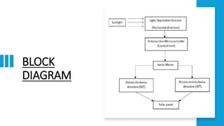
INTRODUCTION
• The biggest crisis we are heading into is
the climate change due to excessive use
of fossil fuels and to overcome these
issues, we have only one solution that
is utilizing Renewable Energy
• Renewable energy is a type of energy
that is harnessed from the nature without
causing ill effects to the environment
• Solar radiation from the sun is collected
by the solar panels and converted into
electrical energy. The output electrical
energy depends on the amount of
sunlight falling on the solar panel.
• Traditionally, solar panels are fixed and
the movement of sun over the horizon
means that the solar panel does not
harness maximum energy most of the
time.
LITERATURE SURVEY
• This paper [1] describes the complete design and
construction of a microcontroller based automatic
solar panel tracking system. The solar panel is fixed
and no automatic tracking of sun light based on its
intensity.
• This paper [2] explain about the effects of global
warming and how can we take advantage from this
effect like how the Solar energy is used for electrical
energy generation. Solar tracking System is based on
AVR microcontroller, which is a 68 brain of a
complete system
• This paper [3] includes a solar array, solar frame and
two actuators, and also it is a dual-axis solar tracker
capable in extreme weather conditions.it has
mechanically linked solar trackers in a large
configuration of solar array, so that they can operate
in unison way
• This paper [4] describe that the targets to reduce
carbon emission and to secure energy supply. It
measures a change in the energy supply system
leading to smart grids for the required innovation. the
key feature in the smart grid application is the
demand side service offered to designated parties by
smart-automation system
How does a Solar Tracker Works?
You must be wondering how does it work? As discussed earlier, the solar panel should face the sun to
harness maximum power. So, our system has two steps, first is to detect the position of sun and
second is to move along with it.
• Detecting the position of the Sun:
We measure the intensity of light with LDRs using Arduino and compare the intensity of light falling on
both LDRs. The LDRs are placed on the edges of the solar panel as shown in the figure below.
• Based on the intensity of light on the
LDR, we give the signal to the servo motor
to cause the movement. When the
intensity of the light falling on the right LDR
is more, the panel turns towards the right
and if the intensity is higher on the left then
the panel slowly turns towards the left side.
• Consider a scenario of a beautiful winter
morning, the sun rises from east side and
therefore it has more light intensity than
the west side, so the panel moves towards
to east side. Throughout the day it will
track the sun and by the evening, sun has
moved towards the west, hence it will have
more intensity than the east direction so
the panel will face the west direction.
Components Required for
Making the Solar Tracker
• 1 x Arduino Uno
• 1 x Servo motor
• 1 x Solar panel
• 2 x LDR
• 2 x 10k Resistor
• Jumper wires
• 1 x MDF board
Schematics and Connection
of the Solar Tracker
• The connection of the circuit is very
straightforward. Here, I used an Arduino Uno as
controller and connected the 2 LDRs to
analogue pin A0 and A1 respectively. Pin 9 of
Arduino is connected to the servo motor. Since,
we have used a 5V servomotor, we don’t
require any external power supply because all
the components can easily be powered the
Arduino itself. All the connections are shown in
the figure below.
BLOCK
DIAGRAM
Assembling the Solar
Tracker
1). The first step before assembling our solar
tracker is to construct the base. For building the
base, I am going to use a MDF board. First step
is to cut and make rectangular pieces of 12*8cm
and 12*2cm from the MDF board as shown in
the figure.
2). Then stick 12*2cm piece vertically to the
12*8cm piece
3). Next step is to attach the solar panel with
the servo motor, for that we require the L-
shaped contraption. For this, I am using a plastic
piece, you can also make this by bending a
plastic sheet or aluminum sheet and finally glue
the solar panel to your contraption.
4). Now, we need to affix the LDRs on opposite sides of the solar panel and to do that, I glued the LDRs
to the panel. Then, I connected the 10k resistors to one any leads of both LDRs and the other side of
resistor should be connected to the ground. These are acting as pull-down resistor. Second terminal of
the LDRs are directly connected to the 5v output. The output of each LDR, I connected it to A1 and A2
pins of Arduino.
5). Next step is to connect the servo motor, a servo motor has three wires, i.e. ground, V_in and a signal
wire. I connected the V_in pin to the 5volt of Arduino, ground to the common ground and the signal wire to
pin-9 of Arduino. That's all about the circuit.
Now, all we have to do is assemble everything. First, I glued the Arduino on the base sheet. Then I
attached the servo motor to the vertical section using glue gun. Finally, I fixed the solar panel with the
servo motor’s hand and secured it with a screw.
Code
• #include <Servo.h>
Servo servo ;
int eastLDR = 0;
int westLDR = 1;
int east = 0;
int west = 0;
int error = 0;
int calibration = 600;
int servoposition = 90;
void setup()
{
servo.attach(9);
}
void loop()
{
east = calibration + analogRead(eastLDR);
west = analogRead(westLDR);
if (east < 350 && west < 350)
{
while (servoposition <= 150)
{
servoposition++;
servo.write(servoposition);
delay(100);
}
}
error = east - west;
if (error > 15)
{
if (servoposition <= 150)
{
servoposition++;
servo.write(servoposition);
}
}
else if (error < -15)
{
if (servoposition > 20)
{
servoposition--;
servo.write(servoposition);
}
}
delay(100);
}
REFERENCES
1. Modeling and Designing of Solar Tracking System using Arduino, Mohit, Subhash
Saxena, Akash deep Singh, Varinder Singh, Harpreet Kaur Chinni
2. SOLAR TRACKING SYSTEM Vaijantee Wakchaure1, Joel Jagtap2, Prof.
Lakshmi Raba B. 3
3. A Fast and Accurate Maximum Power Point Tracker for a Multi-Input Converter
with Wide Range of Soft- Switching Operation for Solar Energy Systems Kajanan
Kanathipan, Sanjida Moury, IEEE Student Member, John Lam, IEEE Senior
Member
4. Solar Tracking System Reshmi Banerjee Electrical Engineering Department, Guru
Nanak Institute of Technology

Sun detecting solar panel using arduino uno

  • 1.
    INTRODUCTION • The biggestcrisis we are heading into is the climate change due to excessive use of fossil fuels and to overcome these issues, we have only one solution that is utilizing Renewable Energy • Renewable energy is a type of energy that is harnessed from the nature without causing ill effects to the environment • Solar radiation from the sun is collected by the solar panels and converted into electrical energy. The output electrical energy depends on the amount of sunlight falling on the solar panel. • Traditionally, solar panels are fixed and the movement of sun over the horizon means that the solar panel does not harness maximum energy most of the time.
  • 2.
    LITERATURE SURVEY • Thispaper [1] describes the complete design and construction of a microcontroller based automatic solar panel tracking system. The solar panel is fixed and no automatic tracking of sun light based on its intensity. • This paper [2] explain about the effects of global warming and how can we take advantage from this effect like how the Solar energy is used for electrical energy generation. Solar tracking System is based on AVR microcontroller, which is a 68 brain of a complete system • This paper [3] includes a solar array, solar frame and two actuators, and also it is a dual-axis solar tracker capable in extreme weather conditions.it has mechanically linked solar trackers in a large configuration of solar array, so that they can operate in unison way • This paper [4] describe that the targets to reduce carbon emission and to secure energy supply. It measures a change in the energy supply system leading to smart grids for the required innovation. the key feature in the smart grid application is the demand side service offered to designated parties by smart-automation system
  • 3.
    How does aSolar Tracker Works? You must be wondering how does it work? As discussed earlier, the solar panel should face the sun to harness maximum power. So, our system has two steps, first is to detect the position of sun and second is to move along with it. • Detecting the position of the Sun: We measure the intensity of light with LDRs using Arduino and compare the intensity of light falling on both LDRs. The LDRs are placed on the edges of the solar panel as shown in the figure below.
  • 4.
    • Based onthe intensity of light on the LDR, we give the signal to the servo motor to cause the movement. When the intensity of the light falling on the right LDR is more, the panel turns towards the right and if the intensity is higher on the left then the panel slowly turns towards the left side. • Consider a scenario of a beautiful winter morning, the sun rises from east side and therefore it has more light intensity than the west side, so the panel moves towards to east side. Throughout the day it will track the sun and by the evening, sun has moved towards the west, hence it will have more intensity than the east direction so the panel will face the west direction.
  • 5.
    Components Required for Makingthe Solar Tracker • 1 x Arduino Uno • 1 x Servo motor • 1 x Solar panel • 2 x LDR • 2 x 10k Resistor • Jumper wires • 1 x MDF board
  • 6.
    Schematics and Connection ofthe Solar Tracker • The connection of the circuit is very straightforward. Here, I used an Arduino Uno as controller and connected the 2 LDRs to analogue pin A0 and A1 respectively. Pin 9 of Arduino is connected to the servo motor. Since, we have used a 5V servomotor, we don’t require any external power supply because all the components can easily be powered the Arduino itself. All the connections are shown in the figure below.
  • 7.
  • 8.
    Assembling the Solar Tracker 1).The first step before assembling our solar tracker is to construct the base. For building the base, I am going to use a MDF board. First step is to cut and make rectangular pieces of 12*8cm and 12*2cm from the MDF board as shown in the figure. 2). Then stick 12*2cm piece vertically to the 12*8cm piece 3). Next step is to attach the solar panel with the servo motor, for that we require the L- shaped contraption. For this, I am using a plastic piece, you can also make this by bending a plastic sheet or aluminum sheet and finally glue the solar panel to your contraption.
  • 9.
    4). Now, weneed to affix the LDRs on opposite sides of the solar panel and to do that, I glued the LDRs to the panel. Then, I connected the 10k resistors to one any leads of both LDRs and the other side of resistor should be connected to the ground. These are acting as pull-down resistor. Second terminal of the LDRs are directly connected to the 5v output. The output of each LDR, I connected it to A1 and A2 pins of Arduino. 5). Next step is to connect the servo motor, a servo motor has three wires, i.e. ground, V_in and a signal wire. I connected the V_in pin to the 5volt of Arduino, ground to the common ground and the signal wire to pin-9 of Arduino. That's all about the circuit. Now, all we have to do is assemble everything. First, I glued the Arduino on the base sheet. Then I attached the servo motor to the vertical section using glue gun. Finally, I fixed the solar panel with the servo motor’s hand and secured it with a screw.
  • 10.
    Code • #include <Servo.h> Servoservo ; int eastLDR = 0; int westLDR = 1; int east = 0; int west = 0; int error = 0; int calibration = 600; int servoposition = 90; void setup() { servo.attach(9); } void loop() { east = calibration + analogRead(eastLDR); west = analogRead(westLDR); if (east < 350 && west < 350) { while (servoposition <= 150) {
  • 11.
    servoposition++; servo.write(servoposition); delay(100); } } error = east- west; if (error > 15) { if (servoposition <= 150) { servoposition++; servo.write(servoposition); } } else if (error < -15) { if (servoposition > 20) { servoposition--; servo.write(servoposition); } } delay(100); }
  • 12.
    REFERENCES 1. Modeling andDesigning of Solar Tracking System using Arduino, Mohit, Subhash Saxena, Akash deep Singh, Varinder Singh, Harpreet Kaur Chinni 2. SOLAR TRACKING SYSTEM Vaijantee Wakchaure1, Joel Jagtap2, Prof. Lakshmi Raba B. 3 3. A Fast and Accurate Maximum Power Point Tracker for a Multi-Input Converter with Wide Range of Soft- Switching Operation for Solar Energy Systems Kajanan Kanathipan, Sanjida Moury, IEEE Student Member, John Lam, IEEE Senior Member 4. Solar Tracking System Reshmi Banerjee Electrical Engineering Department, Guru Nanak Institute of Technology