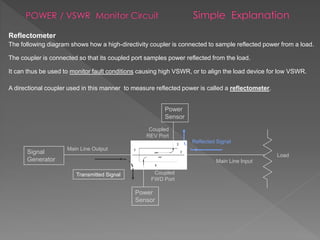
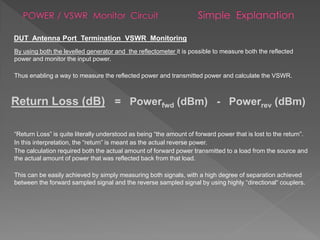
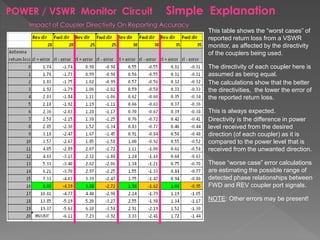
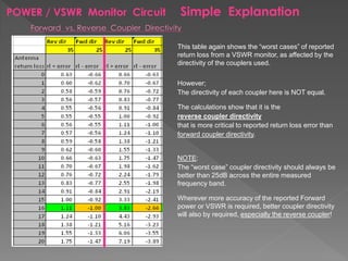
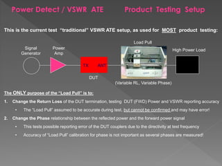
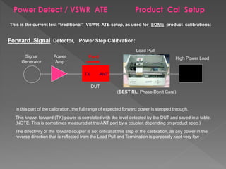
Stephen Nibblett Jan 24, 2013
(2nd version, Presentation originally created Aug 2010)
Power / VSWR Monitor Basics
The main thing to understand is which is the forward direction and which is the reverse direction.
Reverse Coupling is measured from Antenna to Tx
Forward Coupling is measured from Tx to Antenna.
NOTE:
When coupling off an antenna transmission line of a filter, the forward coupling includes the
insertion loss of the filter.
Antenna
Tx
RevFwd
REVERSE
Coupler
FORWARD
Coupler
Reflectometer
The following diagram shows how a high-directivity coupler is connected to sample reflected power from a load.
The coupler is connected so that its coupled port samples power reflected from the load.
It can thus be used to monitor fault conditions causing high VSWR, or to align the load device for low VSWR.
A directional coupler used in this manner to measure reflected power is called a reflectometer.
Power
Sensor
Signal
Generator
Main Line Output
Main Line Input
Coupled
REV Port
Load
Transmitted Signal
Reflected Signal
Power
Sensor
Coupled
FWD Port
Levelled Signal Generator
The forward coupler is connected between a signal generator and a load, such that the forward
coupled port samples power coming from the generator (signal source).
It can thus monitor generator output independent of load conditions.
The forward coupled-port sampled signal can be used to “level” the generator (signal source) output.
Since generator output power variation caused by load mismatch is suppressed by this feedback
technique, the generator-coupler combination will have a source VSWR which is much better than that
of the generator if it were not levelled.
Power
Sensor
Signal
Generator
Main Line Output
Main Line Input
Coupled
REV Port
Load
Transmitted Signal
Reflected Signal
Power
Sensor
Coupled
FWD Port
By using both the levelled generator and the reflectometer it is possible to measure both the reflected
power and monitor the input power.
Thus enabling a way to measure the reflected power and transmitted power and calculate the VSWR.
“Return Loss” is quite literally understood as being “the amount of forward power that is lost to the return”.
In this interpretation, the “return” is meant as the actual reverse power.
The calculation required both the actual amount of forward power transmitted to a load from the source and
the actual amount of power that was reflected back from that load.
This can be easily achieved by simply measuring both signals, with a high degree of separation achieved
between the forward sampled signal and the reverse sampled signal by using highly “directional“ couplers.
Return Loss (dB) = Powerfwd (dBm) - Powerrev (dBm)
DUT Antenna Port Termination VSWR Monitoring
POWER / VSWR Monitor Circuit Simple Explanation
This table shows the “worst cases” of
reported return loss from a VSWR
monitor, as affected by the directivity
of the couplers being used.
The directivity of each coupler here is
assumed as being equal.
The calculations show that the better
the directivities, the lower the error of
the reported return loss.
This is always expected.
Directivity is the difference in power
level received from the desired
direction (of each coupler) as it is
compared to the power level that is
received from the unwanted direction.
These “worse case” error calculations
are estimating the possible range of
detected phase relationships between
FWD and REV coupler port signals.
NOTE: Other errors may be present!
POWER / VSWR Monitor Circuit Simple Explanation
This table again shows the “worst cases” of reported
return loss from a VSWR monitor, as affected by the
directivity of the couplers used.
However;
The directivity of each coupler here is NOT equal.
The calculations show that it is the
reverse coupler directivity
that is more critical to reported return loss error than
forward coupler directivity.
NOTE:
The “worst case” coupler directivity should always be
better than 25dB across the entire measured
frequency band.
Wherever more accuracy of the reported Forward
power or VSWR is required, better coupler directivity
will also by required, especially the reverse coupler!
Power Detect / VSWR Monitor Traditional Test ATE
This is the current test “traditional” VSWR ATE setup, as used for MOST product testing:
The ONLY purpose of the “Load Pull” is to:
1. Change the Return Loss of the DUT termination, testing DUT (FWD) Power and VSWR reporting accuracy
• The “Load Pull” assumed to be accurate during test, but cannot be confirmed and may have error!
2. Change the Phase relationship between the reflected power and the forward power signal
• This tests possible reporting error of the DUT couplers due to the directivity at test frequency
• Accuracy of “Load Pull” calibration for phase is not important as several phases are measured!
Power Detect / VSWR ATE Product Testing Setup
Power
Amp
Signal
Generator
Load Pull
High Power Load
DUT
TX ANT
(Variable RL, Variable Phase)
This is the current test “traditional” VSWR ATE setup, as used for SOME product calibrations:
Power Detect / VSWR ATE Product Cal Setup
Power
Amp
Signal
Generator
Load Pull
High Power Load
DUT
TX ANT
(BEST RL, Phase Don’t Care)
Forward Signal Detector, Power Step Calibration:
Fwd
In this part of the calibration, the full range of expected forward power is stepped through.
This known forward (TX) power is correlated with the level detected by the DUT and saved in a table.
(NOTE: This is sometimes measured at the ANT port by a coupler, depending on product spec.)
The directivity of the forward coupler is not critical at this step of the calibration, as any power in the
reverse direction that is reflected from the Load Pull and Termination is purposely kept very low .
This is the current test “traditional” VSWR ATE setup, used for SOME product calibrations:
Power
Amp
Signal
Generator
Load Pull
High Power Load
DUT
TX ANT
(BEST RL, Phase Don’t Care)
Reverse Signal Detector, Power Step Calibration:
Rev
In this part of the calibration, the full range of expected reverse power is stepped through.
The known reverse (ANT) input power is correlated with the level detected by the DUT and saved in a table.
The directivity of the reverse coupler is very important at this step of the calibration, as the internal DUT
return loss (typically by the filter mis-match) causes some power to be reflected back in the forward direction!
Power Detect / VSWR ATE Product Cal Setup
Equipment Setup For Vectoring Of Simulated Reflection Signal
At the most simple level, this is the signal flow that simulates a load pull return loss and phase:
Reflected Signal Simulation Basic
Concept
Power
Amp 1
Signal
Generator
1
DUT
TX ANT
Fwd
• No understanding of actual FWD output power at DUT ANT, this is needed to set the correct REV level
• No termination of the FWD and REV signals after the DUT, to protect equipment
• No prevention of FWD or REV signal reflections back through DUT, will cause large DUT errors
NOTE: ACTUAL phase of REV signal IS NOT IMPORTANT as long as enough phase points are used!
Rev Power
Amp 2
Signal
Generator
2
There are a few Fundamental Problems in the above circuit:
(Variable Ø , RF Level)
We simply add additional couplers into the circuit, with following conditions:
1. ALL couplers MUST have EXCELLENT directivity, better than 35dB is preferred
2. ALL couplers MUST have EXCELLENT return loss, better than 30dB is preferred
Reflected Signal Simulation Measuring Actual Signal Levels
• No understanding of actual FWD output power at DUT ANT, this is needed to set the correct REV level
Power
Amp 1
Signal
Generator1
DUT
TX ANT
Fwd Rev Power
Amp 2
Signal
Generator 2
(Variable Ø , RF Level)
CPL1
CPL1
Power
Sensor
Coupled FWD
Port
Power
Sensor
Coupled REV
Port
CPL1
CPL2
Power
Sensor
Coupled FWD
Port
Fundamental Problem:
Coupled
REV Port
We now add circulators of the correct frequency band into the circuit, along with the terminations:
1. REV side circulators SHOULD have 25dB return loss (need a bit more, but is resolved on next slide)
2. FWD and REV signal generators MUST have EXCELLENT 10 MHz ref agreement! NO “T” SPLITTERS!
Reflected Signal Simulation Routings and Terminations
• No termination of the FWD and REV signals after the DUT, to protect equipment
• No prevention of FWD or REV signal reflections back through DUT, will cause large DUT errors
Power
Amp 1
Signal
Generator1
DUT
TX ANT
Fwd Rev
Power
Amp 2
Signal
Generator
2
(Variable Ø , RF Level)
CPL1
CPL1
Power
Sensor
Coupled
FWD Port
Power
Sensor
CPL1
CPL2Power
Sensor
Coupled
FWD Port
Fundamental Problems:
1 2
3
12
3
TERM2
TERM1
1 2
3
TERM2
Coupled
REV Port
Finally, we add a high-quality, high-power -3dB attenuator covering the correct frequency bands:
1. Attenuator reduces any reflected FWD signal from circulator mismatch by approx. -6dB (round trip)
2. Attenuator return loss (on DUT side) MUST be better than 30dB, but 35dB or better is preferred!
Reflected Signal Simulation Accuracy Improvement
• No prevention of FWD or REV signal reflections back through DUT, will cause large DUT errors
• FWD signal reflections from equipment should be less 35dBm, no more than less 30dBm!
• This FWD signal “return loss” requirement of -35dB for system includes the ANT RF cable!
Power
Amp 1
Signal
Generator1
DUT
TX ANT
Fwd Rev
Power
Amp 2
Signal
Generator
2
(Variable Ø , RF Level)
CPL1
CPL1
Power
Sensor
Coupled
FWD Port
Power
Sensor
CPL1
CPL2
Power
Sensor
Coupled
FWD Port
Fundamental Problems:
1 2
3
12
3
TERM2
TERM1
1 2
3
TERM2
ATTN1
ATTN
1
Reflected Signal Simulation Test Solution Setup
General Layout :
DUT
TX ANT
Fwd Rev
ANT Output Side
REV Signal Injection
FWD Signal Termination
TX Input Side
FWD Signal Injection
REV Signal Termination
TX Input Side:
• FWD Signal Level Calibrations, with cpl offsets - cable IL, for actual powers at DUT TX PORT
ANT Output Side:
• FWD Signal Level Calibrations with cpl offset s + cable IL, for actual powers at DUT ANT PORT
• REV Signal Level Calibrations, with cpl offsets - cable IL, for actual powers at DUT ANT PORT
NOTE: Calibration Procedure above is simplified, MUST follow actual documented procedures for test setup!
Thank You

Reflectometer Product Cal/Test Signal Simulation

  • 1.
    Stephen Nibblett Jan24, 2013 (2nd version, Presentation originally created Aug 2010)
  • 2.
    Power / VSWRMonitor Basics
  • 3.
    The main thingto understand is which is the forward direction and which is the reverse direction. Reverse Coupling is measured from Antenna to Tx Forward Coupling is measured from Tx to Antenna. NOTE: When coupling off an antenna transmission line of a filter, the forward coupling includes the insertion loss of the filter. Antenna Tx RevFwd REVERSE Coupler FORWARD Coupler
  • 4.
    Reflectometer The following diagramshows how a high-directivity coupler is connected to sample reflected power from a load. The coupler is connected so that its coupled port samples power reflected from the load. It can thus be used to monitor fault conditions causing high VSWR, or to align the load device for low VSWR. A directional coupler used in this manner to measure reflected power is called a reflectometer. Power Sensor Signal Generator Main Line Output Main Line Input Coupled REV Port Load Transmitted Signal Reflected Signal Power Sensor Coupled FWD Port
  • 5.
    Levelled Signal Generator Theforward coupler is connected between a signal generator and a load, such that the forward coupled port samples power coming from the generator (signal source). It can thus monitor generator output independent of load conditions. The forward coupled-port sampled signal can be used to “level” the generator (signal source) output. Since generator output power variation caused by load mismatch is suppressed by this feedback technique, the generator-coupler combination will have a source VSWR which is much better than that of the generator if it were not levelled. Power Sensor Signal Generator Main Line Output Main Line Input Coupled REV Port Load Transmitted Signal Reflected Signal Power Sensor Coupled FWD Port
  • 6.
    By using boththe levelled generator and the reflectometer it is possible to measure both the reflected power and monitor the input power. Thus enabling a way to measure the reflected power and transmitted power and calculate the VSWR. “Return Loss” is quite literally understood as being “the amount of forward power that is lost to the return”. In this interpretation, the “return” is meant as the actual reverse power. The calculation required both the actual amount of forward power transmitted to a load from the source and the actual amount of power that was reflected back from that load. This can be easily achieved by simply measuring both signals, with a high degree of separation achieved between the forward sampled signal and the reverse sampled signal by using highly “directional“ couplers. Return Loss (dB) = Powerfwd (dBm) - Powerrev (dBm) DUT Antenna Port Termination VSWR Monitoring
  • 7.
    POWER / VSWRMonitor Circuit Simple Explanation This table shows the “worst cases” of reported return loss from a VSWR monitor, as affected by the directivity of the couplers being used. The directivity of each coupler here is assumed as being equal. The calculations show that the better the directivities, the lower the error of the reported return loss. This is always expected. Directivity is the difference in power level received from the desired direction (of each coupler) as it is compared to the power level that is received from the unwanted direction. These “worse case” error calculations are estimating the possible range of detected phase relationships between FWD and REV coupler port signals. NOTE: Other errors may be present!
  • 8.
    POWER / VSWRMonitor Circuit Simple Explanation This table again shows the “worst cases” of reported return loss from a VSWR monitor, as affected by the directivity of the couplers used. However; The directivity of each coupler here is NOT equal. The calculations show that it is the reverse coupler directivity that is more critical to reported return loss error than forward coupler directivity. NOTE: The “worst case” coupler directivity should always be better than 25dB across the entire measured frequency band. Wherever more accuracy of the reported Forward power or VSWR is required, better coupler directivity will also by required, especially the reverse coupler!
  • 9.
    Power Detect /VSWR Monitor Traditional Test ATE
  • 10.
    This is thecurrent test “traditional” VSWR ATE setup, as used for MOST product testing: The ONLY purpose of the “Load Pull” is to: 1. Change the Return Loss of the DUT termination, testing DUT (FWD) Power and VSWR reporting accuracy • The “Load Pull” assumed to be accurate during test, but cannot be confirmed and may have error! 2. Change the Phase relationship between the reflected power and the forward power signal • This tests possible reporting error of the DUT couplers due to the directivity at test frequency • Accuracy of “Load Pull” calibration for phase is not important as several phases are measured! Power Detect / VSWR ATE Product Testing Setup Power Amp Signal Generator Load Pull High Power Load DUT TX ANT (Variable RL, Variable Phase)
  • 11.
    This is thecurrent test “traditional” VSWR ATE setup, as used for SOME product calibrations: Power Detect / VSWR ATE Product Cal Setup Power Amp Signal Generator Load Pull High Power Load DUT TX ANT (BEST RL, Phase Don’t Care) Forward Signal Detector, Power Step Calibration: Fwd In this part of the calibration, the full range of expected forward power is stepped through. This known forward (TX) power is correlated with the level detected by the DUT and saved in a table. (NOTE: This is sometimes measured at the ANT port by a coupler, depending on product spec.) The directivity of the forward coupler is not critical at this step of the calibration, as any power in the reverse direction that is reflected from the Load Pull and Termination is purposely kept very low .
  • 12.
    This is thecurrent test “traditional” VSWR ATE setup, used for SOME product calibrations: Power Amp Signal Generator Load Pull High Power Load DUT TX ANT (BEST RL, Phase Don’t Care) Reverse Signal Detector, Power Step Calibration: Rev In this part of the calibration, the full range of expected reverse power is stepped through. The known reverse (ANT) input power is correlated with the level detected by the DUT and saved in a table. The directivity of the reverse coupler is very important at this step of the calibration, as the internal DUT return loss (typically by the filter mis-match) causes some power to be reflected back in the forward direction! Power Detect / VSWR ATE Product Cal Setup
  • 13.
    Equipment Setup ForVectoring Of Simulated Reflection Signal
  • 14.
    At the mostsimple level, this is the signal flow that simulates a load pull return loss and phase: Reflected Signal Simulation Basic Concept Power Amp 1 Signal Generator 1 DUT TX ANT Fwd • No understanding of actual FWD output power at DUT ANT, this is needed to set the correct REV level • No termination of the FWD and REV signals after the DUT, to protect equipment • No prevention of FWD or REV signal reflections back through DUT, will cause large DUT errors NOTE: ACTUAL phase of REV signal IS NOT IMPORTANT as long as enough phase points are used! Rev Power Amp 2 Signal Generator 2 There are a few Fundamental Problems in the above circuit: (Variable Ø , RF Level)
  • 15.
    We simply addadditional couplers into the circuit, with following conditions: 1. ALL couplers MUST have EXCELLENT directivity, better than 35dB is preferred 2. ALL couplers MUST have EXCELLENT return loss, better than 30dB is preferred Reflected Signal Simulation Measuring Actual Signal Levels • No understanding of actual FWD output power at DUT ANT, this is needed to set the correct REV level Power Amp 1 Signal Generator1 DUT TX ANT Fwd Rev Power Amp 2 Signal Generator 2 (Variable Ø , RF Level) CPL1 CPL1 Power Sensor Coupled FWD Port Power Sensor Coupled REV Port CPL1 CPL2 Power Sensor Coupled FWD Port Fundamental Problem:
  • 16.
    Coupled REV Port We nowadd circulators of the correct frequency band into the circuit, along with the terminations: 1. REV side circulators SHOULD have 25dB return loss (need a bit more, but is resolved on next slide) 2. FWD and REV signal generators MUST have EXCELLENT 10 MHz ref agreement! NO “T” SPLITTERS! Reflected Signal Simulation Routings and Terminations • No termination of the FWD and REV signals after the DUT, to protect equipment • No prevention of FWD or REV signal reflections back through DUT, will cause large DUT errors Power Amp 1 Signal Generator1 DUT TX ANT Fwd Rev Power Amp 2 Signal Generator 2 (Variable Ø , RF Level) CPL1 CPL1 Power Sensor Coupled FWD Port Power Sensor CPL1 CPL2Power Sensor Coupled FWD Port Fundamental Problems: 1 2 3 12 3 TERM2 TERM1 1 2 3 TERM2
  • 17.
    Coupled REV Port Finally, weadd a high-quality, high-power -3dB attenuator covering the correct frequency bands: 1. Attenuator reduces any reflected FWD signal from circulator mismatch by approx. -6dB (round trip) 2. Attenuator return loss (on DUT side) MUST be better than 30dB, but 35dB or better is preferred! Reflected Signal Simulation Accuracy Improvement • No prevention of FWD or REV signal reflections back through DUT, will cause large DUT errors • FWD signal reflections from equipment should be less 35dBm, no more than less 30dBm! • This FWD signal “return loss” requirement of -35dB for system includes the ANT RF cable! Power Amp 1 Signal Generator1 DUT TX ANT Fwd Rev Power Amp 2 Signal Generator 2 (Variable Ø , RF Level) CPL1 CPL1 Power Sensor Coupled FWD Port Power Sensor CPL1 CPL2 Power Sensor Coupled FWD Port Fundamental Problems: 1 2 3 12 3 TERM2 TERM1 1 2 3 TERM2 ATTN1 ATTN 1
  • 18.
    Reflected Signal SimulationTest Solution Setup General Layout : DUT TX ANT Fwd Rev ANT Output Side REV Signal Injection FWD Signal Termination TX Input Side FWD Signal Injection REV Signal Termination TX Input Side: • FWD Signal Level Calibrations, with cpl offsets - cable IL, for actual powers at DUT TX PORT ANT Output Side: • FWD Signal Level Calibrations with cpl offset s + cable IL, for actual powers at DUT ANT PORT • REV Signal Level Calibrations, with cpl offsets - cable IL, for actual powers at DUT ANT PORT NOTE: Calibration Procedure above is simplified, MUST follow actual documented procedures for test setup!
  • 19.