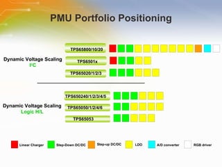
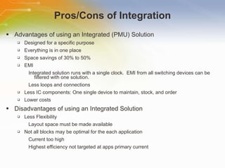
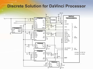
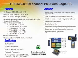
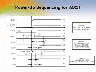
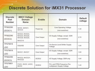
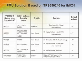
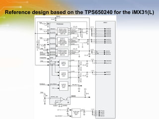
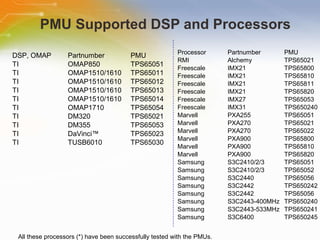
20. PMU Supported DSP and Processors All these processors (*) have been successfully tested with the PMUs.
21.
Editor's Notes
This is a training module on Texas Instruments Power Management Units
Welcome to the training module on Powering Microprocessors with Power Management Units (PMUs) for Embedded Processors This training module introduces TI’s PMU portfolio, their features, and reference designs for different embedded microprocessors.
Texas Instruments has a wide selection of Power Management Units. Each family of Power Management Units has their own set of unique features as depicted in this page. Take for example, the TPS658xx family and the TPS6501x family. They both have an integrated Linear Charger. However, some differences between the two families do exist.
The Linear Charger in the TPS6501x family is designed to charge a single Lithium-Ion Battery. The Linear Charger operates independent of the rest of the Power Management Unit. The charger starts charging when an input voltage on either AC or USB input is present. By default, it attempts to charge from the AC input. If both the AC input and the USB input are present, the AC input takes precedence. The output of the Charger connects directly to the Battery and can also be connected to the Converter inputs of the Power Management Unit.
The Charging Profile shown begins on power up. A Battery Preconditioning phase allows deeply discharged cells to be revived by applying a pre-charge current if the battery voltage is below the minimum charge voltage threshold. The load current in the pre-conditioning phase must be lower than the pre-charge current and must allow the battery voltage to rise above the minimum charge voltage threshold within the specified t(prechg) parameter. This t(prechg) parameter serves as a safety timer during the preconditioning phase. If the t(prechg) time is exceeded, the TPS6501x will disable the timer and indicate a faulty battery. If the charge voltage surpasses the minimum charge voltage within the t(prechg) time, the TPS6501x switches over to the Regulation Current. This Charge Current is dependent on whether the AC input or the USB input is being used to charge the battery. As a safety backup, if the taper current is not detected within the t(chg) specified time, the TPS6501x turns off the charger and indicates a fault. A normal charging cycle will cause the charge voltage to reach the desired Regulation Voltage. The TPS6501x monitors the charging current to make sure it reaches the taper threshold. Once reached, the taper timer, t(taper) is initiated and the charge is terminated after the timer expires.
The TPS658xx family adds to the Linear Charger of the TPS6501x family. The TPS658xx integrates a Power Path MOSFET which allows the battery to charge while an external input power source runs the system at the same time. This integrated MOSFET (the Battery Switch) can operate as either an ON/OFF switch or as a linear pass element under distinct operating conditions. If either the AC or USB inputs are connected, the TPS658xx device regulates the voltage to the system at 4.6V. If the charger function is enabled, the Battery Switch will be turned ON and thereby charging the battery. If both the AC or USB inputs are not present, the Battery Switch is turned ON so that the Battery supplies power to the system.
The charging profile for the TPS658xx mimics that of the TPS6501x. However, the linear charger in this device adds yet another feature. If the junction temperature of the IC exceeds 125 º C during normal operating conditions, an integrated thermal control loop will be activated.
The activation of the integrated thermal control loop circuit changes the charging profile for the TPS658xx by adding the Thermal Regulation Phase. The thermal control loop overrides the other charger control loops and thereby, reduces the charge current until the IC junction temperature returns to 125 º C.
A common feature among Texas Instruments’ Power Management Units is the Dynamic Voltage Scaling controlled by an I 2 C Bus. This feature allows a processor to dynamically change the output voltage based on system demand. In battery powered applications, Dynamic Voltage Scaling helps reduce power consumption by reducing the supply voltage as the clock frequency is reduced. The output voltage is controlled by using the I 2 C Bus to write to a specific register. Depending on the PMU being used, the number of bits in the register will vary. In this particular case, the output voltage is controlled by five bits with each bit having a bit weight of 25 millivolts. Given the thirty two different combinations available, this particular output voltage can range from 0.8V to 1.6V.
In conjunction with the Dynamic Voltage Scaling is the Slew Rate Control. This allows the output voltage to change from one level to another in a predefined rate. For applications that don’t require I 2 C Dynamic Voltage Scaling, Texas Instruments also offers Power Management Units that use discrete inputs to set the desired output voltage. The discrete inputs are typically driven by the GPIO lines of a processor and the output voltage is allowed to swing between two preset values. The preset values are dependent on which Power Management Unit is used. To better serve the market needs, Texas Instruments offers a few options for each family of Power Management Units that incorporate the discrete Dynamic Voltage Scaling.
Given all the options available, the System Designer is always faced with the decision on whether to use an integrated power solution or to use a discrete solution. Every application is different and trade-offs must be performed. An integrated solution provides numerous advantages but so does a discrete solution. With a Power Management Unit from Texas Instruments, one big advantage gained is ‘time to market’. The TI Power Management Units are designed to simplify the design process.
Looking at an example using the DaVinci Processor, a discrete solution can be implemented as shown. However, if a Power Management Unit, like the TPS65023 is used, the design can be greatly simplified.
The use of the TPS65023 Power Management Unit eliminates the need to use six discrete components. Even though the DaVinci processor only requires three separate voltage rails, additional components are needed in the discrete solution in order to satisfy the power up sequence. This power up sequence can be satisfied with the TPS65023 and its unique integrated features. For additional information on powering up the DaVinci Processor using the TPS65023 PMU, an application note has been generated and is available on the web under the TPS65023 Product Folder.
The Freescale iMX31 processor also requires a specific power up sequence. The power up sequence for this processor is so critical that the iMX31 processor datasheet warns the System Designer that ‘any deviation from the specified sequence may lead to excessive current draw during the power up phase or prevent the device from booting up properly, or may cause irreversible damage to the processor’. Each voltage domain is grouped based on functionality and then defined as to when to power up its rail. In some cases, one or more groupings are allowed to power up at the same time.
The TPS65024x family of Power Management Units are designed with independent enables for each DCDC Converter. This allows the system designer the flexibility in setting up a specific power up sequence. The TPS65024x family consists of six devices. Each device has three step-down converters and three Linear Dropout Regulators. The only difference between each of the six devices is the preset voltage settings of the DCDC3 Converter. The DCDC3 Converter has two fixed output voltages that are set using the discrete Dynamic Voltage Scaling inputs. Each of the preset voltage values is shown on the front page of the datasheet, making it simple for the System Designer to choose the device which best fits the target processor. With its small package outline and integrated functionality, the TPS65024x devices offer an ideal solution for handheld systems. In addition, with converter efficiencies in the 90% range, less power is wasted and battery life is extended.
Looking at the voltage requirements for the iMX31 processor and comparing that to the TPS65024x options available, the TPS650240 stands out as the best fit. The iMX31 sequencing scheme previously shown as a state diagram is shown here in a timing diagram. With its separate enables, the TPS650240 Power Management Unit is able to satisfy the power up sequence for the iMX31 processor.
System Designers have various options for implementing their power solutions. This table shows one such option for the iMX31 processor using discrete devices. It uses three DCDC converters and three LDOs. The power up sequence can be managed by using the enable for each of the selected devices. This option is simplified with the use of three different devices (the TPS62290 DCDC Converter, the TPS79918 LDO and the TPS79901 LDO) to implement the six voltage domains.
Using a Power Management Unit instead of discrete devices simplifies the solution by reducing the number of devices needed from six to two (the TPS650240 Power Management Unit and a TPS79901 LDO). The power up sequence is easily implemented and as an added bonus, the System Designer is able to save on board space.
Texas Instruments has created a reference design for the iMX31 processor using the TPS650240 Power Management Unit. In addition, an application note showing more detailed information has also been generated. This application note, titled “TI Power Management Solution for the Freescale iMX31 Processor” can be found on the TI web page.
Texas Instruments has validated numerous Power Management Unit reference designs to make sure they work with the targeted processors. A list of the targeted processors and the corresponding Power Management Unit is shown on this page for easy cross reference.
Thank you for taking the time to view this presentation on “ Power Management Units (PMUs) for Embedded Processors)” . If you would like to learn more or go on to purchase some of these devices, you may either click on the part list link, or simply call our sales hotline. For more technical information you may either visit the TI site, or if you would prefer to speak to someone live, please call our hotline number, or even use our ‘live chat’ online facility.