Download to read offline


![Control Units CU230 optimized for pumps,
fans, compressors
CU240 optimized for general applications in machinery construction,
such as conveyor belts, mixers, extruders
Architecture Application-optimized number of I/O Basic number of I/O Standard number of I/O with inte-
grated safety technology
Mounting dimensions [WxHxD] 73 x 199 x 58.4 73 x 199 x 46 73 x 199 x 46
Communication functions
PROFINET – CU240E-2 PN, CU240E-2 PN-F
PROFIBUS CU230P-2 DP CU240B-2 DP CU240E-2 DP, CU240E-2 DP-F
PROFIsafe – – CU240E-2 DP-F, CU240E-2 PN-F
Serial RS 485 interfaces with
Modbus RTU and USS protocol
CU230P-2 HVAC CU240B-2 CU240E-2, CU240E-2 F
BACnet MS/TP CU230P-2 HVAC – –
CANopen CU230P-2 CAN – –
USB interface 4 4 4
Safety functions acc. to Category 3 of EN 954-1 or acc. to SIL2 of IEC 61508
Safety functions:
STO
STO, SS1, SLS, SDI
STO, SS1, SLS, SDI, SSM
–
–
–
–
–
–
CU240E-2, CU240E-2 DP, CU240E-2 PN
CU240E-2 F
CU240E-2 DP-F, CU240E-2 PN-F
Electrical data
Supply voltage 24 V DC (via Power Module or externally)
Digital inputs,
parameterizable, electrically isolated
6 4 6
Digital inputs, fail safe
parameterizable, electrically isolated
– – CU240E-2, CU240E-2 DP: 1
CU240E-2 DP-F: 3
Analog inputs,
parameterizable
2, can be switched between –10 to
+10 V and 0/4 to 20 mA, can be used
as digital inputs
1, can be switched between 0/4 to
20 mA and NI1000 / PT1000
1, NI1000 / PT1000
1
0 to 10 V, 0 to 20 mA and can be
switched between –10 and +10 V
Can be used as additional digital
inputs
2
0 to 10 V, 0 to 20 mA and can be
switched between –10 and +10 V
0 to 10 V and 0 to 20 mA
Can be used as additional digital
inputs
Digital outputs,
parameterizable, electrically isolated
2 (relay, changeover contacts),
250 V AC, 2 A, 30 V DC, 5 A
1 (relay, NO contact ), 30 V DC, 0.5 A
1 (transistor), 30 V DC, 0.5 A 3 (1 x transistor, 2 x relay, changeover
contact), 30 V DC, 0.5 A
Analog outputs,
parameterizable
2, can be switched between 0 to 10 V
and 0/4 to 20 mA
1 (AO0: 0 to 10 V and 0 to 20 mA) 2 (AO0: 0 to 10 V and 0 to 20 mA,
AO1: 0 mA to 20 mA)
Functions
Skip frequency range 4, programmable
Fixed frequencies 16, programmable
Closed-loop control technique/
open-loop control modes
Vector (SLVC), V/f (linear, square-law,
free, FCC, ECO)
Vector (SLVC), V/f (linear, square-law, free, FFC, ECO),
closed-loop torque control
Operating functions PID controller, hibernation, 3x freely
programmable digital time switches,
automatic restart, flying restart, slip
compensation, kinetic buffering (only
in conjunction with PM240 Power
Modules), and many more
Positioning down ramp, automatic restart, flying restart, slip compensation,
jogging, kinetic buffering, motor temperature monitoring, free function blocks,
and many more
Protection functions Motor temperature monitoring with and without temperature sensor
Mechanical data
Degree of protection IP20
Software
STARTER, SIZER, DT Configurator x x x
Startdrive CU240B-2 DP CU240E-2 DP
Accessories
IOP, BOP-2, shield connection plate, PC Connection Kit-2, memory card (MMC or SD)
13
Control Units](https://image.slidesharecdn.com/brochureg120-211023084425/75/T-i-Brochure-bi-n-t-n-siemens-Sinamic-G120-13-2048.jpg)


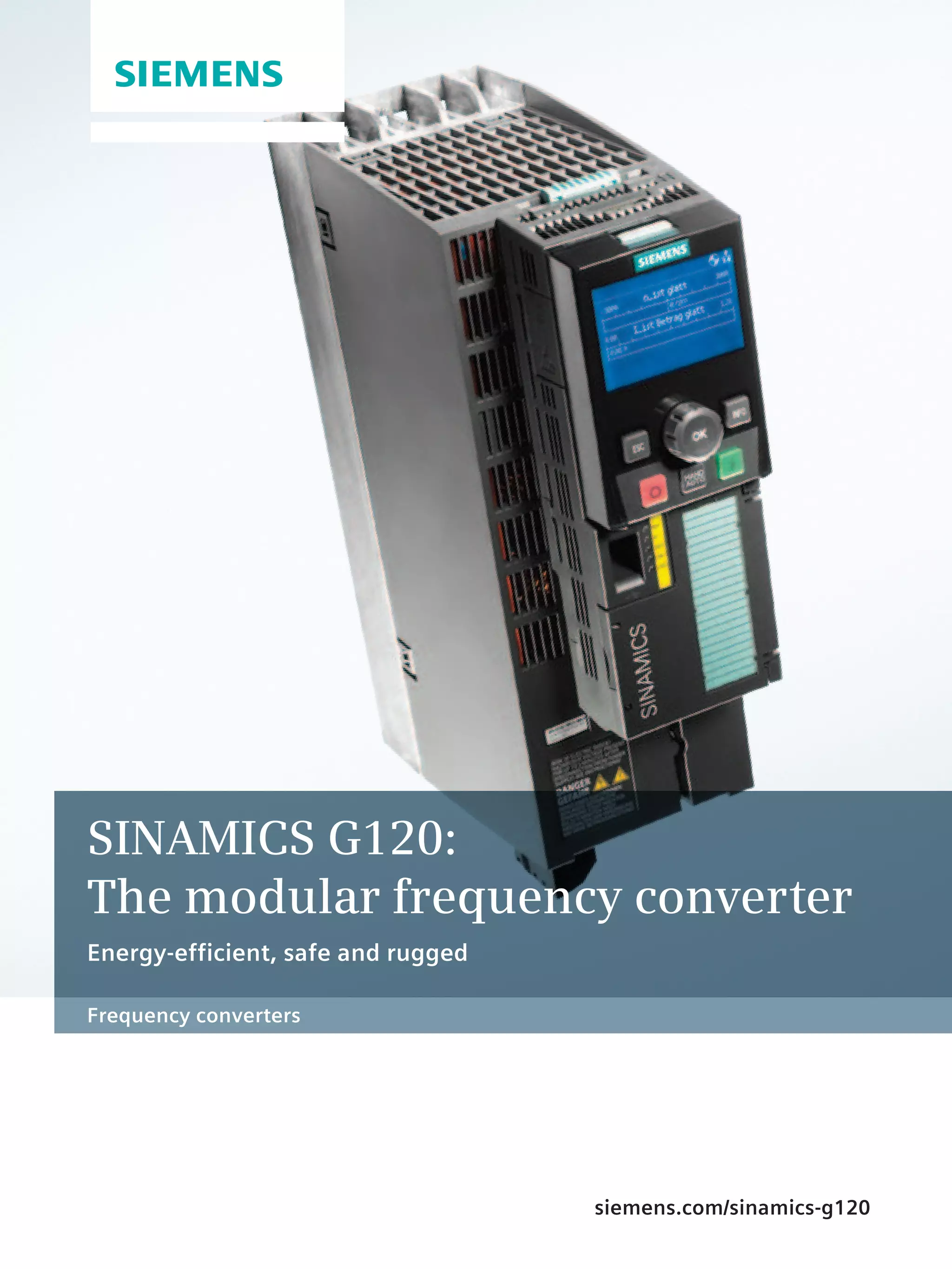
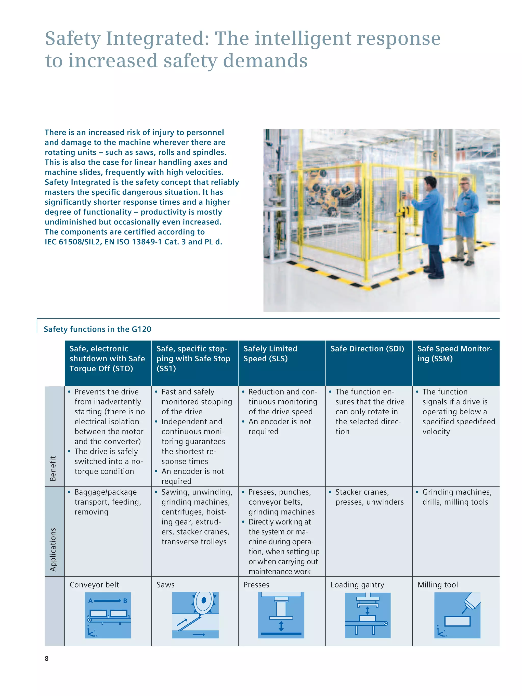
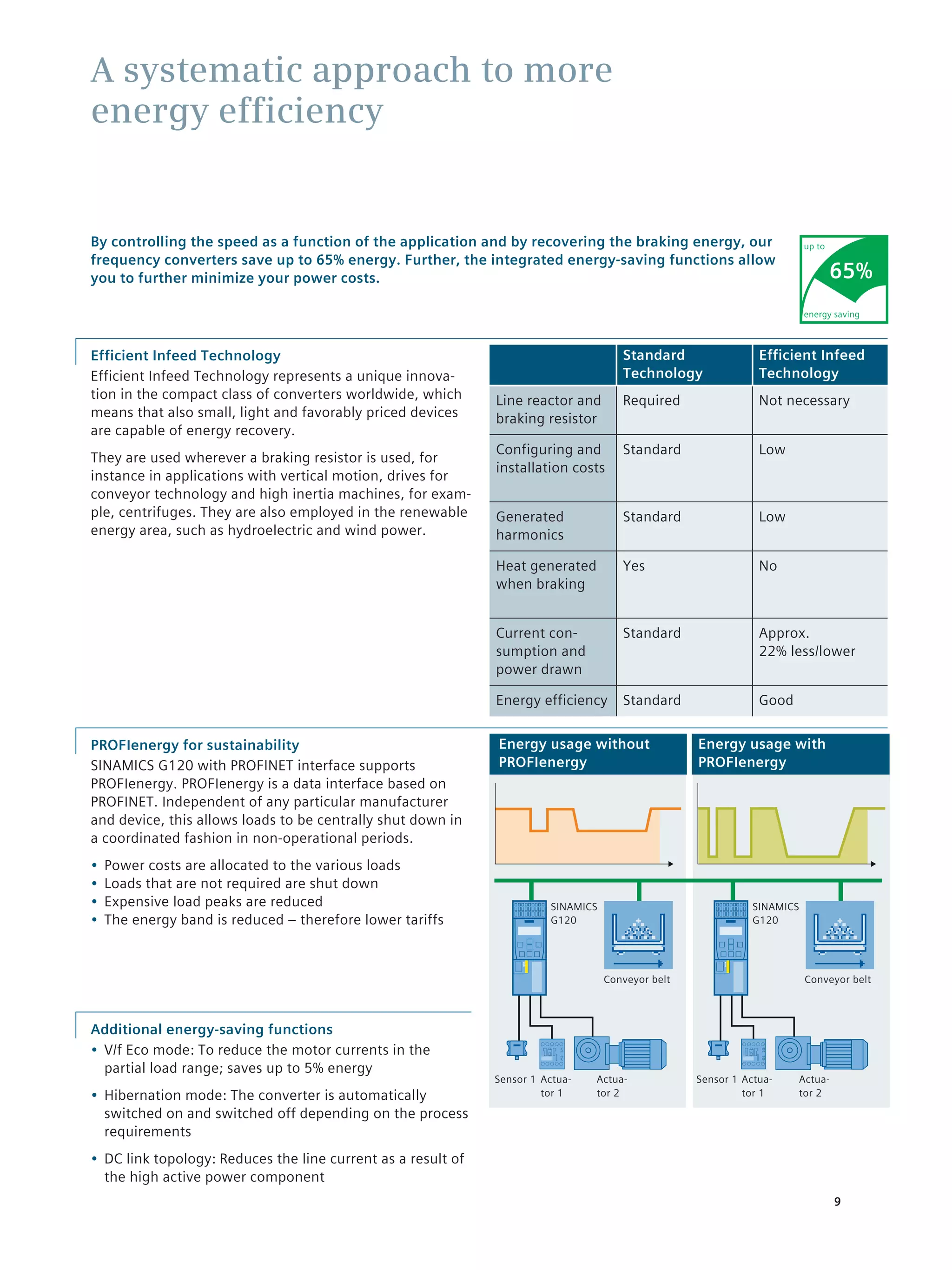
The Siemens Sinamics G120 is a modular frequency converter designed for various industrial applications, offering energy efficiency, flexibility, and safety. Its components can easily be configured to meet specific operational needs, supporting a wide range of power ratings from 0.37 kW to 250 kW. Enhanced safety features and advanced energy recovery functions make the Sinamics G120 a reliable solution for both standard and complex drive tasks across different sectors.