Download to read offline

![─ 4 ─
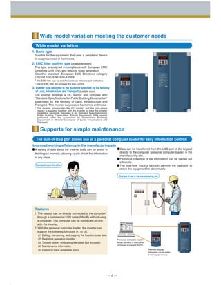
250
200
100
0
-100
-200
-250
500 1000 1500
Torque(%)
Motor speed
r/min
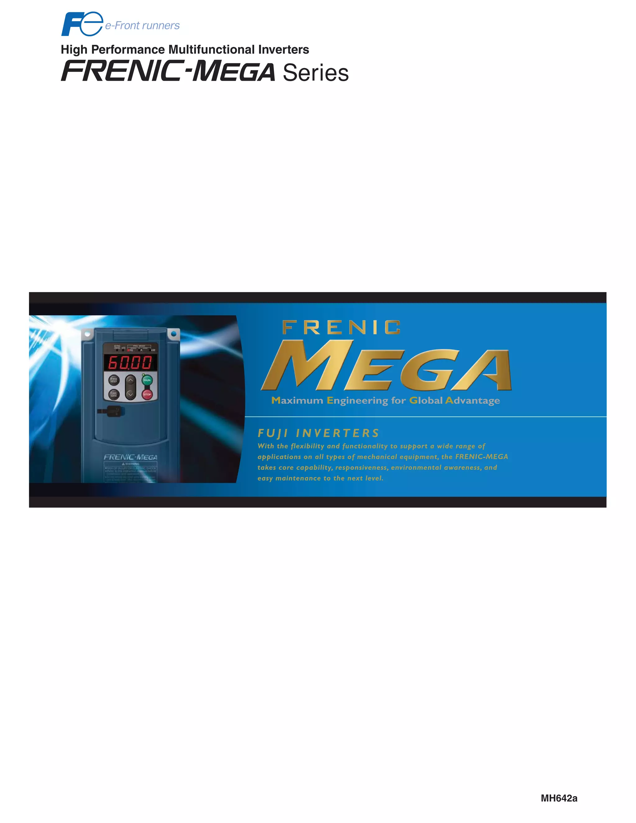
Example torque characteristics 5.5kW
Our previous model
Previous model
Approx. 4ms
Approx. 6ms
Terminal response time
example per command
Response time shortened
by approx. 2 ms
150ms
150ms
:
:
[ ]
( )
Example:
Example:
Best vector control for the general-purpose inverter in the class
Besides the dynamic torque vector control, the inverter is
equipped with the motor constant tuning for compensating
even a voltage error of the main circuit devices and the
magnetic flux observer of a new system. This realizes a
high starting torque of 200% even at a low-speed rotation of
0.3Hz.
Speed control range: 1:1500
Speed response: 100Hz
Speed control accuracy: ±0.01%
Current response: 500Hz
Torque accuracy: ±10%
* The option card is required separately. (Available soon)
* The above specifications may vary depending on the
environment or conditions for use.
Ideal for highly accurate control such as positioning
Speed control range: 1:200
Speed response: 20Hz
Speed control accuracy: ±0.5%
Current response: 500Hz
Torque accuracy: ±10%
Zero speed torque: ±20%
100% torque or
over *
Maximizing the performance of a general-purpose motor
PG vector control
Effective in providing highly accurate control for applications
such as offset printing
Sensorless vector control (available soon)
Useful for the application that requires a high starting
torque, such as the gondola type
multi-level car parking tower
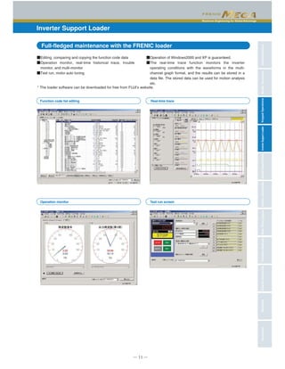
Fuji’soriginaldynamictorquevectorcontrolhasfurtherevolved.
The inverter performs short-time acceleration and
deceleration with the maximum capacity by achieving better
time rating of the overload ratings compared with our
previous models. This improves the operation efficiency of
the equipment such as cutting machine or conveyance
machine.
Overload durability: 200% for 3 sec and 150% for 1 min.
Improved durability in overload operation
When a remarkable load fluctuation occurs, the inverter
provides the torque response in the class-top level. It
controls the flux to minimize the fluctuation in the motor
speed while suppressing the vibration. This function is best
suited for the equipment that requires stable speed such as
a cutting machine.
Improved reaction to the fluctuation of impact load
The terminal response to the operation commands has had an
established reputation. FRENIC-MEGA has further shortened this
response time, achieving the industry-top response time.
This function is effective in shortening the tact time per cycle and
effective for use in the process including frequent repetitions.
Quicker response to the operation commands
A brake circuit is built in the 22kW or smaller models as a
standard function. These inverters are applicable to the
machine that uses regenerative load such as a vertical
conveyance machine.
(The 7.5kW or smaller models also incorporate a braking
resistor.)
* Since the capacity has been further expanded, 30kW to 55
kW models in 200V series and 30kW to 110kW models in
400V series can be manufactured on request.
Expanded capacity for the brake circuit built-in models
* The voltage detection option is
required separately. (Available soon)
MEGA controls the speed and
torque better than the previous
models in the settled state.
The standard model is available in two specifications
concerning the operation load.
Classification
HD (High duty) spec
LD (Low duty) spec
Major use
Operation under heavy load
Operation under light load
Overload
200% for 3 sec, 150% for 1 min
120% for 1 min
Approx. 4ms
Response start
OFF
ON
Motor
speed
Load
torque](https://image.slidesharecdn.com/catalog-frenic-mega-fuji-electric-160426030600/85/Catalog-bi-n-t-n-Frenic-Mega-Fuji-Electric-Beeteco-com-5-320.jpg)
![Maximum Engineering for Global Advantage
CharacteristicsModelVariationsStandardSpecificationsKeypadOperationsInverterSupportLoaderBasicWiringDiagramCommonSpecificationsExternalDimensionsFunctionSettingsWarrantyVariations
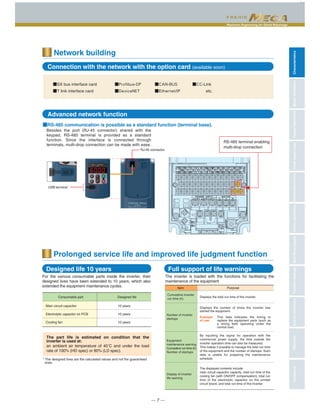
Main speed
(line speed)
Input range: 0 to +10[V], -10 to 10[V], 4 to 20mA
Frequency
setting output
Frequency
setting input 100%
95%
Frequency
setting input
Frequency
setting
output
Frequency
setting
output
Frequency
setting
output
Ratio setting
95%
90% 82%
Upper limit
Reference position
F
Dancer roll
Line speed is adjusted
according to the position
of the dancer roll.
Fixed roll Fixed roll
Winding
machine
Lower limit
Rotation speed control
Position information
Potentiometer, etc.
ex.0V to 10V
= x
Analog input (Ratio setting)
~
─ 5 ─
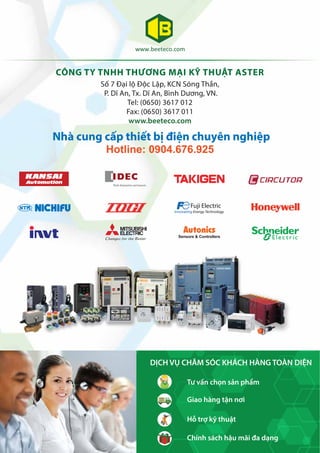
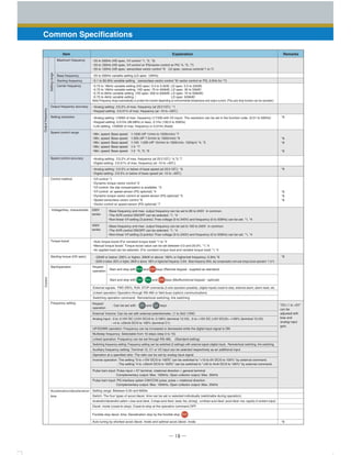
Accommodating various applications
This control function is best suited for the application that requires
highly accurate positioning such as that of the conveyance
machine. By combined use of the position control device (APR)
and PG vector control, the position control accuracy has been
remarkably improved. Shortened positioning time by this function
will be helpful to reduce the tact time of a cycle.
The pulse train input function is equipped as a
standard function.
It is possible to issue the speed command with the pulse
train input (single-phase pulse and a sign of command
value) from the pulse generator, etc.
(Maximum pulse input: 100kpps)
This function is useful for controlling more than one inverter.
Ratio operation
The ratio operation is the function particularly convenient for
adjusting two or more conveyance systems. The ratio of the
main axis speed to the two or more trailing axes can be set
as a frequency command. On the machine that handles load
variation such as a conveyance machine, the conveyance
speed can be adjusted easily.
Convenient function for operations at the specified speed
The inverter protects the braking resistor by monitoring the
braking transistor operation. The inverter outputs an
exclusive signal on detection of the braking transistor
abnormality. A circuit for shutting off the input power supply
is provided outside of the inverter. When this signal is
output, the power is shut off; thus protecting the braking
circuit.
Thorough protection of the braking circuit
The reliability of the brake
signal was increased for uses
such as vertical conveyance.
Conventionally, the current
value and the frequency have
been monitored when the brake
signal is output. By adding a
torque value to these two
values, the brake timing can be
adjusted more easily.
Optimum function for preventing an object from slipping down
The PID value, calculated by comparing the target value
and the feedback value, is added to or subtracted from the
reference speed. Since the PID calculator gain (in
proportional range) can be set to a low value, the inverter
can be applied to the automatic control system that requires
quick response such as a speed controller.
Dancer control function optimum for winding control
(1) Analog input (4 to 20mA) through 2 terminals with
polarity (2) Low liquid level stop function (Pressurized
operation is possible before low liquid level stop.) (3) Non-
linear V/f pattern at 3 points (4) Dummy failure output function
(5) Selection of up to the 4th motor (6) S-shape accel./decel.
range setting (7) Detecting disconnection of the PID
feedback (8) Output frequency: 500Hz
More functions are available to meet various requirements
MEGA World Keeps Expanding
PG option card for positioning control (available soon)
Logic input/output can be easily created by parameter setting.
This makes it possible to simplify the peripheral circuits.
The customized logic interface function is adopted in the inverter body.(Available soon)
This function is effective in adjusting the stop timing or the braking
torque when the equipment such as a conveyance machine is
stopped by positioning of the motor. This function is helpful when
torque is applied externally or holding torque is required during the
stop time. The tact time per cycle will be reduced by shortened
deceleration time.
Introducing servo lock function (PG option card). (Available soon)
The interface is available
in 10 steps using 2 inputs,
1 output, logical operation,
and the timer function.
Example: Fixed length marking system
MEGA
Pulse
PLC Motor
M
MCMC
ECLB
or
MCCB
BS11
BS12
R1
Marker
Object to be marked
Position detection sensor [LS]
Moving direction
Position control section
Belt conveyor
Target stop point
Reference position
Start point](https://image.slidesharecdn.com/catalog-frenic-mega-fuji-electric-160426030600/85/Catalog-bi-n-t-n-Frenic-Mega-Fuji-Electric-Beeteco-com-6-320.jpg)
![Maximum Engineering for Global Advantage
CharacteristicsModelVariationsStandardSpecificationsKeypadOperationsInverterSupportLoaderBasicWiringDiagramCommonSpecificationsExternalDimensionsFunctionSettingsWarrantyVariations
─ 9 ─
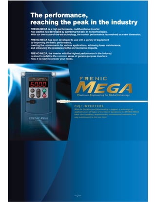
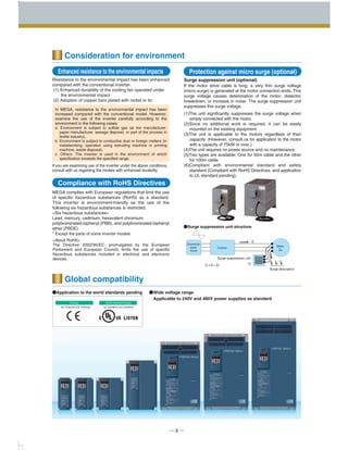
Model Variations
0.4
0.75
1.5
2.2
3.7
5.5
7.5
11
15
18.5
22
30
37
45
55
75
90
110
132
160
200
220
280
・
・
・
・
630
710
FRN0.4G1S-2J
FRN0.75G1S-2J
FRN1.5G1S-2J
FRN2.2G1S-2J
FRN3.7G1S-2J
FRN5.5G1S-2J
FRN7.5G1S-2J
FRN11G1S-2J
FRN15G1S-2J
FRN18.5G1S-2J
FRN22G1S-2J
FRN30G1S-2J
FRN37G1S-2J
FRN45G1S-2J
FRN55G1S-2J
FRN75G1S-2J
FRN90G1S-2J
FRN5.5G1S-2J
FRN7.5G1S-2J
FRN11G1S-2J
FRN15G1S-2J
FRN18.5G1S-2J
FRN22G1S-2J
FRN30G1S-2J
FRN37G1S-2J
FRN45G1S-2J
FRN55G1S-2J
FRN75G1S-2J
FRN90G1S-2J
FRN0.4G1S-4J
FRN0.75G1S-4J
FRN1.5G1S-4J
FRN2.2G1S-4J
FRN3.7G1S-4J
FRN5.5G1S-4J
FRN7.5G1S-4J
FRN11G1S-4J
FRN15G1S-4J
FRN18.5G1S-4J
FRN22G1S-4J
FRN30G1S-4J
FRN37G1S-4J
FRN45G1S-4J
FRN55G1S-4J
FRN75G1S-4J
FRN90G1S-4J
FRN110G1S-4J
FRN132G1S-4J
FRN160G1S-4J
FRN200G1S-4J
FRN220G1S-4J
FRN280G1S-4J
・
・
・
・
FRN630G1S-4J
FRN5.5G1S-4J
FRN7.5G1S-4J
FRN11G1S-4J
FRN15G1S-4J
FRN18.5G1S-4J
FRN22G1S-4J
FRN30G1S-4J
FRN37G1S-4J
FRN45G1S-4J
FRN55G1S-4J
FRN75G1S-4J
FRN90G1S-4J
FRN110G1S-4J
FRN132G1S-4J
FRN160G1S-4J
FRN200G1S-4J
FRN220G1S-4J
・
・
・
・
FRN500G1S-4J
FRN630G1S-4J
3-phase 200 V series
Basic type
3-phase 400 V series
Standard
applied motor
(kW)
Available soon
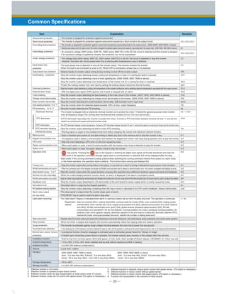
Model list
How to read the inverter model
Caution The contents of this catalog are provided to help you select the product model that is best for you. Before the actual use, be sure to read the
User’s Manual thoroughly for proper operations.
*When HD spec of FRN55G1S-2J or FRN55G1S-4J is ordered, no DC reactor is supplied as a standard device. But, when LD spec is ordered,
the DC reactor is supplied as a standard device.
FRN 0.75 G 1 S - 2 J
Code
FRN
Series name
FRENIC series
Code
J
Destination / Instruction manual
Japan / Japanese
Code
S
Enclosure
Standard (basic type)
Code
2
4
Input power source
3-phase 200V
3-phase 400V
Code Applicable motor rating
0.4
0.75
to
55
75
90
0.4kW
0.75kW
to
55kW
75kW
90kW
Code
G
Applicable range
High performance, multifunctional type
Code
1
Order of development
Series
[Available soon] The EMC filter built-in type and the zero-phase reactor/DC reactor built-in type that complies with the guideline supervised by the
Ministry of Land, Infrastructure and Transport will be added to the lineups.
HD spec (150%) LD spec (120%) HD spec (150%) LD spec (120%)
HD : High Duty spec 200% for 3 sec, 150% for 1min
LD : Low Duty spec 120% for 1 min](https://image.slidesharecdn.com/catalog-frenic-mega-fuji-electric-160426030600/85/Catalog-bi-n-t-n-Frenic-Mega-Fuji-Electric-Beeteco-com-10-320.jpg)
![─ 12 ─
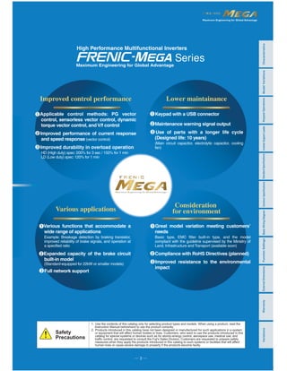
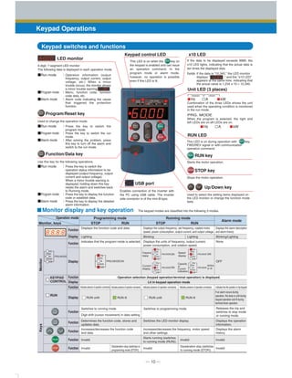
Standard Specifications (Basic type)
HD (High Duty) spec for heavy load
Three-phase 200V series
LD (Low Duty) spec for light load
Nominal applied motor [kW] (*1) 0.4
1.1
1.6
3.1
0.6
3.2
5.3
1.2
6.1
9.5
2.2
8.9
13.2
3.1
15
22.2
5.2
21.1
31.5
7.4
28.8
42.7
10
42.2
60.7
15
57.6
80.1
20
71.0
97.0
25
84.4
112
30
114
151
40
138
185
48
167
225
58
203
270
71
282
ー
98
334
ー
116
0.75
1.9
1.5
3.0
2.2
4.2
3.7
6.8
5.5
10
7.5
14
18.5
28
22
34
30
45
37
55
45
68
55
81
11
18
15
24
3 5 8 11 18 27 37 49 63 76 90 119 146 180 215 283 346
Rated capacity [kVA] (*2)
Rated voltage [V] (*3)
Rated Current [A] (*4)
Overload capability
Rated frequency [Hz]
Voltage, frequency variations
Required power supply capacity (*8)
Torque [%] (*9)
Braking transistor
Minimum connective resistance
Torque [%]
Built-in braking resistance
DC injection braking
Rated current [A] (*7)
0.4 0.75 1.5 2.2 3.7 5.5 7.5 11 15 18.5 22 30 37 45 55
75
107
75
90
131
90
Item Specifications
Type (FRN□□□G1S-2J)
Voltage:+10 to -15% (Voltage unbalance:2% or less (*6)) Frequency:+5 to -5%
Three-phase 200 to 240V(with AVR) Three-phase 200 to 230V(with AVR)
DC reactor (DCR) (*10)
Applicable safety standards
Enclosure (IEC60529)
Cooling method
Weight/Mass [kg]
InputratingsBrakingOutputratings
100
180%
40
180%
24
180%
16
180%
12
180%
8
180%
6
180%
4
180%
150% for 1min, 200% for 3.0s
50, 60Hz
Three-phase 200 to 240V, 50/60Hz
ー
ー
Three-phase 200 to 220V, 50Hz
Three-phase 200 to 230V, 60Hz
Single-phase 200 to 220V, 50Hz
Single-phase 200 to 230V, 60Hz
Single-phase 200 to 240V, 50/60Hz Single-phase 200 to 230V, 50/60Hz
150% 100% 20% 10 to15%
Built-in
Standard accessory
ー
ー
ー
ー
ー
100Ω
5s
40Ω 20Ω
5 3 5 3 2 3 2
1.8 2 2.8 3 3.2 6.5 7 7 9.5 9.5 10 26 32 42 43
Starting frequency:0.0 to 60.0Hz, Braking time: 0.0 to 30.0s, Braking level:0 to 100%
Optional
UL508C, C22.2No.14 (pending), EN61800-5-1:2003
IP20 (IEC60529) closed type UL open type (UL 50)
Natural cooling
IP00 open type,ULopen type
Fan cooling
with DCR
without DCR
withDCR
Braking time[s]
%ED
Main circuit power
Phases, voltage, frequency
Auxiliary control power input
Phases, voltage, frequency
Auxiliary power input for fan
Phases, voltage, frequency (*5)
Nominal applied motor [kW] (*1) ー
ー
ー
ー
ー
ー
ー
ー
ー
ー
7.5
11
11
16
15
20
18.5
25
22
30
30
43
37
55
45
68
55
81
75
107
90
131
110
158
ー
ー
ー
ー
ー
ー
ー
ー
ー
ー
ー
ー
ー
ー
ー
28.8
42.7
10
42.2
60.7
15
57.6
80.1
20
71.0
97.0
25
84.4
112
30
114
151
40
138
185
48
167
225
58
203
270
71
282
ー
98
334
ー
116
410
ー
143
ー ー ー
ー
ー
ー
ー
ー
ー
ー
ー
ー
ー
ー
ー
ー
ー
ー
ー
ー
ー
ー ー
31.8
(29)
46.2
(42)
59.4
(55)
74.8
(68)
88
(80)
115
(107)
146 180 215 283 346 415
Rated capacity [kVA] (*2)
Rated voltage [V] (*3)
Overload capability
Rated frequency [Hz]
Voltage, frequency variations
Required power supply capacity (*8)
Torque [%] (*9)
Braking transistor
Minimum connective resistance
Torque [%]
Built-in braking resistance
Rated current [A] (*7)
0.4 0.75 1.5 2.2 3.7 5.5 7.5 11 15 18.5 22 30 37 45 55 75 90
Item Specifications
Type (FRN□□□G1S-2J)
Voltage:+10 to -15% (Voltage unbalance:2% or less (*6)) Frequency:+5 to -5%
Three-phase 200 to 230V(with AVR)Three-phase 200 to 240V(with AVR)
DC reactor (DCR) (*10)
Applicable safety standards
Enclosure (IEC60529)
Cooling method
Weight/Mass [kg]
InputratingsBrakingOutputratings
16
130%
12
120%
8
130%
6
140%
4
130%
4
150%
DC injection braking
120% for 1min
50, 60Hz
Three-phase 200 to 240V, 50/60Hz
Single-phase 200 to 240V,50/60Hz
ー
Three-phase 200 to 220V, 50Hz
Three-phase 200 to 230V, 60Hz
Single-phase 200 to 220V, 50Hz
Single-phase 200 to 230V, 60Hz
Single-phase 200 to 230V, 50/60Hz
70% 15% 7 to12%
Built-in
Standard accessory
ー
ー
ー
ー
ー
3.7s
2.2
3.4s
1.4
20Ω
6.5 7 7 9.5 9.5 10 26 32 42 43
Starting frequency:0.0 to 60.0Hz, Braking time: 0.0 to 30.0s, Braking level:0 to 80%
Optional
UL508C, C22.2No.14 (pending), EN61800-5-1:2003
IP20 (IEC60529) closed type UL open type(UL 50)
Fan cooling
IP00 open typeULopen type
with DCR
without DCR
withDCR
Braking time〔s〕
%ED
Main circuit power
Phases, voltage, frequency
Auxiliary control power input
Phases, voltage, frequency
Auxiliary power input for fan
Phases, voltage, frequency (*5)
(*1) Fuji's 4-pole standard motor
(*2) Rated capacity is calculated by assuming the output rated voltage as 220V for three-phase 200V series and 440V for three-phase 400V series.
(*3) Output voltage cannot exceed the power supply voltage.
(*4) When using the inverter in the ambient temperature of 40℃ or over and with carrier frequency at 3kHz or higher, adjust the current under continuous running to be the value in ( ) or lower by controlling the load.
(*5) The auxiliary power input is used as an AC fan power input when combining the unit such as high power factor PWM converter with power regenerative function.(Generally not used.)
(*6) Interphase voltage unbalance ratio[%] = (max. voltage [V] - min. voltage [V])/3-phase average voltage [V]×67(See IEC61800-3.) Use the DC reactor (ACR: optional) when used with 2 to 3 % of unbalance ratio.
(*7) The value is calculated on assumption that the inverter is connected with a power supply capacity of 500kVA (or 10 times the inverter capacity if the inverter capacity exceeds 50kVA) and %X is 5%.
(*8) Obtained when a DC reactor (DCR) is used.
(*9) Average braking torque obtained by use of a motor. (Varies with the efficiency of the motor.)
(*10) The 55kW DC reactor (DCR) is optional with HD spec, and is provided as a standard accessory with LD spec.
Rated Current [A] (*4)](https://image.slidesharecdn.com/catalog-frenic-mega-fuji-electric-160426030600/85/Catalog-bi-n-t-n-Frenic-Mega-Fuji-Electric-Beeteco-com-13-320.jpg)
![Maximum Engineering for Global Advantage
CharacteristicsModelVariationsStandardSpecificationsKeypadOperationsInverterSupportLoaderBasicWiringDiagramCommonSpecificationsExternalDimensionsFunctionSettingsWarrantyVariations
─ 13 ─
(0.4 to 55kW) HD (High Duty) spec for heavy load
Three-phase 400V series
(75 to 630kW) HD (High Duty) spec for heavy load
InputratingsBrakingOutputratings
(*1) Fuji's 4-pole standard motor
(*2) Rated capacity is calculated by assuming the output rated voltage as 220V for three-phase 200V series and 440V for three-phase 400V series.
(*3) Output voltage cannot exceed the power supply voltage.
(*5) The auxiliary power input is used as an AC fan power input when combining the unit such as high power factor PWM converter with power regenerative function.(Generally not used.)
(*6) Interphase voltage unbalance ratio[%] = (max. voltage [V] - min. voltage [V])/3-phase average voltage [V]×67(See IEC61800-3.) Use the DC reactor (ACR: optional) when used with 2 to 3 % of unbalance ratio.
(*7) The value is calculated on assumption that the inverter is connected with a power supply capacity of 500kVA (or 10 times the inverter capacity if the inverter capacity exceeds 50kVA) and %X is 5%.
(*8) Obtained when a DC reactor (DCR) is used.
(*9) Average braking torque obtained by use of a motor. (Varies with the efficiency of the motor.)
(*10) The 55kW DC reactor (DCR) is optional with HD spec, and is provided as a standard accessory with LD spec.
0.4
1.1
0.85
1.7
0.6
1.6
3.1
1.2
3.0
5.9
2.1
4.5
8.2
3.2
7.5
13.0
5.2
10.6
17.3
7.4
14.4
23.2
10
21.1
33
15
28.8
43.8
20
35.5
52.3
25
42.2
60.6
30
57.0
77.9
40
68.5
94.3
48
83.2
114
58
102
140
71
0.75
1.9
1.5
2.8
2.2
4.1
3.7
6.8
5.5
10
7.5
14
18.5
29
22
34
30
45
37
57
45
69
55
85
11
18
15
24
1.5 2.5 4 5.5 9 13.5 18.5 24.5 32 39 45 60 75 91 112
0.4 0.75 1.5 2.2 3.7 5.5 7.5 11 15 18.5 22 30 37 45 55
Item Specifications
Voltage:(10 to -15% (Voltage unbalance:2% or less (*6)) Frequency:+5 to -5%
Three-phase 380 to 480V (with AVR)
200
180%
160
180%
96
180%
64
180%
48
180%
32
180%
24
180%
16
180%
150% for 1min, 200% for 3.0s
50, 60Hz
Three-phase 380 to 480V, 50/60Hz
ー
ー
Single-phase 380 to 480V, 50/60Hz
150% 100% 20% 10 to 15%
Built-in ー
ー
ー
ー
ー
720Ω 470Ω
5s
160Ω 80Ω
5 3 5 3 2 3 2
1.8 2 2.8 3 3.2 6.5 7 7 9.5 9.5 10 2626 32 36
Starting frequency:0.0 to 60.0Hz, Braking time: 0.0 to 30.0s, Braking level:0 to 100%
Optional
UL508C, C22.2No.14 (pending), EN61800-5-1:2003
IP20 (IEC60529) closed type, UL open type (UL 50)
Natural cooling
IP00 open type, UL open type
Fan cooling
Nominal applied motor [kW] (*1) 75
114
138
ー
96
164
ー
114
210
ー
140
238
ー
165
286
ー
199
357
ー
248
390
ー
271
500
ー
347
559
ー
388
628
ー
436
705
ー
489
881
ー
611
1115
ー
773
90
134
110
160
132
192
160
231
200
287
220
316
355
495
400
563
500
731
630
891
280
396
315
445
150 176 210 253 304 377 415 520 585 650 740 960 1170
Rated capacity [kVA] (*2)
Rated voltage [V] (*3)
Rated Current [A] (*4)
Overload capability
Rated frequency [Hz]
Required power supply capacity [kVA] (*8)
Torque [%] (*9)
Braking transistor
Minimum connective resistance
Torque [%]
DC injection braking
Rated current [A] (*7)
75 90 110 132 160 200 220 280 315 355 400 500 630
Item Specifications
Type(FRN□□□G1S-4J)
Voltage:+10 to -15% (Voltage unbalance:2% or less (*6)) Frequency:+5 to -5%
Three-phase 380 to 480V (with AVR)
DC reactor (DCR) (*10)
Applicable safety standards
Enclosure (IEC60529)
Cooling method
Weight/Mass [kg]
150% for 1min, 200% for 3.0s
50, 60Hz
Three-phase 380 to 480V, 50Hz
Three-phase 380 to 480V, 60Hz
Single-phase 380 to 440V, 50Hz
Single-phase 380 to 480V, 60Hz
Single-phase 380 to 480V, 50/60Hz
10 to 15%
ー
ー
43
Starting frequency:0.0 to 60.0Hz, Braking time: 0.0 to 30.0s, Braking level:0 to 100%
Standard accessory
UL508C, C22.2No.14 (pending), EN61800-5-1:2003
IP20(IEC60529) closed type, UL open type (UL 50)
Fan cooling
with DCR
without DCR
with DCR
Main circuit power
Phases, voltage, frequency
Auxiliary control power input
Phases, voltage, frequency
Auxiliary power input for fan
Phases, voltage, frequency (*5)
Voltage, frequency variations
Nominal applied motor [kW] (*1)
Rated capacity [kVA] (*2)
Rated voltage [V] (*3)
Rated Current [A] (*4)
Overload capability
Rated frequency [Hz]
Voltage, frequency variations
Required power supply capacity (*8)
Torque [%] (*9)
Braking transistor
Minimum connective resistance
Torque [%]
Built-in braking resistance
DC injection braking
Rated current [A] (*7)
Type (FRN□□□G1S-4J)
DC reactor (DCR) (*10)
Applicable safety standards
Enclosure (IEC60529)
Cooling method
Weight/Mass [kg]
InputratingsBrakingOutputratings
with DCR
without DCR
withDCR
Braking time[s]
%ED
Main circuit power
Phases, voltage, frequency
Auxiliary control power input
Phases, voltage, frequency
Auxiliary power input for fan
Phases, voltage, frequency (*5)](https://image.slidesharecdn.com/catalog-frenic-mega-fuji-electric-160426030600/85/Catalog-bi-n-t-n-Frenic-Mega-Fuji-Electric-Beeteco-com-14-320.jpg)
![─ 14 ─
Standard Specifications (Basic type)
(5.5 to 55kW) LD (Low Duty) spec for light load
Three-phase 400V series
(75 to 630kW) LD (Low Duty) spec for light load
(*1) Fuji's 4-pole standard motor
(*2) Rated capacity is calculated by assuming the output rated voltage as 220V for three-phase 200V series and 440V for three-phase 400V series.
(*3) Output voltage cannot exceed the power supply voltage.
(*5) The auxiliary power input is used as an AC fan power input when combining the unit such as high power factor PWM converter with power regenerative function.(Generally not used.)
(*6) Interphase voltage unbalance ratio[%] = (max. voltage [V] - min. voltage [V])/3-phase average voltage [V]×67(See IEC61800-3.) Use the DC reactor (ACR: optional) when used with 2 to 3 % of unbalance ratio.
(*7) The value is calculated on assumption that the inverter is connected with a power supply capacity of 500kVA (or 10 times the inverter capacity if the inverter capacity exceeds 50kVA) and %X is 5%.
(*8) Obtained when a DC reactor (DCR) is used.
(*9) Average braking torque obtained by use of a motor. (Varies with the efficiency of the motor.)
(*10) The 55kW DC reactor (DCR) is optional with HD spec, and is provided as a standard accessory with LD spec.
ー
ー
ー
ー
ー
ー
ー
ー
ー
ー
ー
ー
ー
ー
ー
ー
ー
14.4
23.2
10
21.1
33.0
15
28.8
43.8
20
35.5
52.3
25
42.2
60.6
30
57.0
77.9
40
68.5
94.3
48
83.2
114
58
102
140
71
138
ー
96
ー
ー
ー
ー
ー
ー
ー
ー
7.5
12
11
17
22
33
30
45
37
57
45
69
55
85
75
114
15
22
18.5
28
ー ー ー
ー
ー
ー
ー
ー
ー
ー
ー
ー
ー
ー
ー
ー
ー
ー
ー
ー
ー
ー ー 16.5 23 30.5 37 45 60 75 91 112 150
0.4 0.75 1.5 2.2 3.7 5.5 7.5 11 15 18.5 22 30 37 45 55
Item Specifications
Type (FRN□□□G1S-4J)
Voltage:+10 to -15% (Voltage unbalance:2% or less (*6)) Frequency:+5 to -5%
Three-phase 380 to 480V (with AVR)
64
130%
48
120%
32
130%
24
140%
16
150%
16
130%
120% for 1min
50, 60Hz
Three-phase 380 to 480V, 50/60Hz
Single-phase 380 to 480V, 50/60Hz
ー
70% 15% 7 to 12%
Built-in ー
ー
ー
ー
ー
3.7s
2.2
3.4s
1.4
80Ω
6.5 7 7 9.5 9.5 10 2626 32 36
Starting frequency:0.0 to 60.0Hz, Braking time: 0.0 to 30.0s, Braking level:0 to 80%
Optional
UL508C, C22.2No.14 (pending), EN61800-5-1:2003
IP20 (IEC60529) closed type, UL open type (UL 50)
Fan cooling
IP00 open type,ULopen type
Nominal applied motor [kW] (*1) 90
134
164
ー
114
210
ー
140
238
ー
165
286
ー
199
357
ー
248
390
ー
271
500
ー
347
628
ー
436
705
ー
489
789
ー
547
881
ー
611
1115
ー
773
1256
ー
871
110
160
132
192
160
231
200
287
220
316
280
396
450
640
500
731
630
891
710
1044
355
495
400
563
176 210 253 304 377 415 520 650 740 840 960 1170 1370
Rated capacity [kVA] (*2)
Rated voltage [V] (*3)
Rated Current [A] (*4)
Overload capability
Rated frequency [Hz]
Required power supply capacity [kVA] (*8)
Torque [%] (*9)
Braking transistor
Minimum connective resistance
Torque [%]
DC injection braking
Rated current [A] (*7)
75 90 110 132 160 200 220 280 315 355 400 500 630
Item Specifications
Type (FRN□□□G1S-4J)
Voltage:+10 to -15% (Voltage unbalance:2% or less (*6)) Frequency:+5 to -5%
Three-phase 380 to 480V(with AVR)
DC reactor (DCR) (*10)
Applicable safety standards
Enclosure (IEC60529)
Cooling method
Weight/Mass [kg]
120% for 1min
50, 60Hz
Three-phase 380 to 440V/50Hz
Three-phase 380 to 480V/60Hz
Single-phase 380 to 440V/50Hz
Single-phase 380 to 480V/60Hz
Single-phase 380 to 440V, 50/60Hz
7 to 12%
ー
ー
43
Starting frequency:0.0 to 60.0Hz, Braking time: 0.0 to 30.0s, Braking level:0 to 80%
Standard accessory
UL508C, C22.2No.14 (pending), EN61800-5-1:2003
IP00 open type, UL open type
Fan cooling
Main circuit power
Phases, voltage, frequency
Auxiliary control power input
Phases, voltage, frequency
Auxiliary power input for fan
Phases, voltage, frequency (*5)
Voltage, frequency variations
Standardaccessory
Nominal applied motor [kW] (*1)
Rated capacity [kVA] (*2)
Rated voltage [V] (*3)
Rated Current [A] (*4)
Overload capability
Rated frequency [Hz]
Voltage, frequency variations
Required power supply capacity (*8)
Torque [%] (*9)
Braking transistor
Minimum connective resistance
Torque [%]
Built-in braking resistance
DC injection braking
Rated current [A] (*7)
DC reactor (DCR) (*10)
Applicable safety standards
Enclosure (IEC60529)
Cooling method
Weight/Mass [kg]
InputratingsBrakingOutputratings
with DCR
without DCR
withDCR
Braking time[s]
%ED
Main circuit power
Phases, voltage, frequency
Auxiliary control power input
Phases, voltage, frequency
Auxiliary power input for fan
Phases, voltage, frequency (*5)
InputratingsBrakingOutputratings
with DCR
without DCR
withDCR](https://image.slidesharecdn.com/catalog-frenic-mega-fuji-electric-160426030600/85/Catalog-bi-n-t-n-Frenic-Mega-Fuji-Electric-Beeteco-com-15-320.jpg)
![Maximum Engineering for Global Advantage
CharacteristicsModelVariationsStandardSpecificationsKeypadOperationsInverterSupportLoaderBasicWiringDiagramCommonSpecificationsExternalDimensionsFunctionSettingsWarrantyVariations
─ 15 ─
Standard Specifications (EMC filter buit-in type)
HD (High Duty) spec for heavy load
Three-phase 200V series
LD (Low Duty) spec for light load
0.4
1.1
1.6
3.1
0.6
3.2
5.3
1.2
6.1
9.5
2.2
8.9
13.2
3.1
15
22.2
5.2
21.1
31.5
7.4
28.8
42.7
10
42.2
60.7
15
57.6
80.1
20
71
97
25
84.4
112
30
114
151
40
138
185
48
167
225
58
203
270
71
282
ー
98
334
ー
116
0.75
1.9
1.5
3
2.2
4.2
3.7
6.8
5.5
10
7.5
14
18.5
28
22
34
30
45
37
55
45
68
55
81
11
18
15
24
3 5 8 11 18 27 37 49 63 76 90 119 146 180 215 283 346
0.4 0.75 1.5 2.2 3.7 5.5 7.5 11 15 18.5 22 30 37 45 55
75
107
75
90
131
90
Item Specifications
Type(FRN□□□G1E-2J)
Voltage:+10 to -15% (Voltage unbalance:2% or less (*6)) Frequency:+5 to -5%
Three-phase 200 to 240V (with AVR) Three-phase 200 to 230V (with AVR)
100
180%
40
180%
24
180%
16
180%
12
180%
8
180%
6
180%
4
180%
150% for 1min, 200% for 3.0s
50, 60Hz
Three-phase 200 to 240V, 50/60Hz
ー
ー
Three-phase 200 to 220V, 50Hz
Three-phase 200 to 230V, 60Hz
Single-phase 200 to 220V/50Hz
Single-phase 200 to 230V/60Hz
Single-phase 200 to 240V, 50/60Hz Single-phase 200 to 230V, 50/60Hz
150% 100% 20% 10 to 15%
Built-in
Standard accessory
ー
ー
ー
ー
ー
100Ω
5s
40Ω 20Ω
5 3 5 3 2 3 2
2.0 2.2 3.0 3.2 3.4 7.1 7.6 7.6 10.7 10.7 11.2 26 32 42 43
Starting frequency:0.0 to 60.0Hz, Braking time: 0.0 to 30.0s, Braking level:0 to 100%
EMC standard compliance: emission, immunity: category C3(2nd Env.)(EN61800-3:2004)
Optional
UL508C, C22.2No.14 (pending), EN61800-5-1:2003
IP20 closed type, UL open type
Natural cooling
IP00 open type, UL open type
Fan cooling
ー
ー
ー
ー
ー
ー
ー
ー
ー
ー
7.5
11
11
16
15
20
18.5
25
22
30
30
43
37
55
45
68
55
81
75
107
90
131
110
158
ー
ー
ー
ー
ー
ー
ー
ー
ー
ー
ー
ー
ー
ー
ー
28.8
42.7
10
42.2
60.7
15
57.6
80.1
20
71.0
97.0
25
84.4
112
30
114
151
40
138
185
48
167
225
58
203
270
71
282
ー
98
334
ー
116
410
ー
143
ー ー ー
ー
ー
ー
ー
ー
ー
ー
ー
ー
ー
ー
ー
ー
ー
ー
ー
ー
ー
ー ー
31.8
(29)
46.2
(42)
59.4
(55)
74.8
(68)
88
(80)
115
(107)
146 180 215 283 346 415
0.4 0.75 1.5 2.2 3.7 5.5 7.5 11 15 18.5 22 30 37 45 55 75 90
Item Specifications
Type(FRN□□□G1E-2J)
Voltage:+10 to -15% (Voltage unbalance:2% or less (*6)) Frequency:+5 to -5%
Three-phase 200 to 230V (with AVR)Three-phase 200 to 240V (with AVR)
16
130%
12
120%
8
130%
6
140%
4
130%
4
150%
120% for 1min
50, 60Hz
Three-phase 200 to 240V,50/60Hz
Single-phase 200 to 240V,50/60Hz
ー
Three-phase 200 to 220V,50Hz
Three-phase 200 to 230V,60Hz
Three-phase 200 to 220V,0Hz
Three-phase 200 to 230V,60Hz
Single-phase 200 to 230V,50/60Hz
70% 15% 7 to 12%
Built-in
Standard accessory
ー
ー
ー
ー
ー
3.7s
22
3.4s
14
20Ω
7.1 7.6 7.6 10.7 10.7 11.2 26 32 42 43
Starting frequency:0.0 to 60.0Hz, Braking time: 0.0 to 30.0s, Braking level:0 to 80%
EMC standard compliance: emission, immunity: category C3(2nd Env.)(EN61800-3:2004)
Optional
UL508C, C22.2No.14 (pending), EN61800-5-1:2003
IP20 (IEC60529) closed type, UL open type (UL 50)
Fan cooling
IP00 open type, UL open type
(*1) Fuji's 4-pole standard motor
(*2) Rated capacity is calculated by assuming the output rated voltage as 220V for three-phase 200V series and 440V for three-phase 400V series.
(*3) Output voltage cannot exceed the power supply voltage.
(*5) The auxiliary power input is used as an AC fan power input when combining the unit such as high power factor PWM converter with power regenerative function.(Generally not used.)
(*6) Interphase voltage unbalance ratio[%] = (max. voltage [V] - min. voltage [V])/3-phase average voltage [V]×67(See IEC61800-3.) Use the DC reactor (ACR: optional) when used with 2 to 3 % of unbalance ratio.
(*7) The value is calculated on assumption that the inverter is connected with a power supply capacity of 500kVA (or 10 times the inverter capacity if the inverter capacity exceeds 50kVA) and %X is 5%.
(*8) Obtained when a DC reactor (DCR) is used.
(*9) Average braking torque obtained by use of a motor. (Varies with the efficiency of the motor.)
(*10) The 55kW DC reactor (DCR) is optional with HD spec, and is provided as a standard accessory with LD spec.
Nominal applied motor [kW] (*1)
Rated capacity [kVA] (*2)
Rated voltage [V] (*3)
Rated Current [A] (*4)
Overload capability
Rated frequency [Hz]
Voltage, frequency variations
Required power supply capacity (*8)
Torque [%] (*9)
Braking transistor
Minimum connective resistance
Torque [%]
Built-in braking resistance
DC injection braking
Rated current [A] (*7)
EMC filter
DC reactor (DCR) (*10)
Applicable safety standards
Enclosure (IEC60529)
Cooling method
Weight/Mass [kg]
InputratingsBrakingOutputratings
with DCR
without DCR
withDCR
Braking time[s]
%ED
Main circuit power
Phases, voltage, frequency
Auxiliary control power input
Phases, voltage, frequency
Auxiliary power input for fan
Phases, voltage, frequency (*5)
Nominal applied motor [kW] (*1)
Rated capacity [kVA] (*2)
Rated voltage [V] (*3)
Overload capability
Rated frequency [Hz]
Voltage, frequency variations
Required power supply capacity (*8)
Torque [%] (*9)
Braking transistor
Minimum connective resistance
Torque [%]
Built-in braking resistance
DC injection braking
Rated current [A] (*7)
EMC filter
DC reactor (DCR) (*10)
Applicable safety standards
Enclosure (IEC60529)
Cooling method
Weight/Mass [kg]
InputratingsBrakingOutputratings
with DCR
without DCR
withDCR
Braking time[s]
%ED
Main circuit power
Phases, voltage, frequency
Auxiliary control power input
Phases, voltage, frequency
Auxiliary power input for fan
Phases, voltage, frequency (*5)
Rated Current [A] (*4)](https://image.slidesharecdn.com/catalog-frenic-mega-fuji-electric-160426030600/85/Catalog-bi-n-t-n-Frenic-Mega-Fuji-Electric-Beeteco-com-16-320.jpg)
![─ 16 ─
Standard Specifications (EMC filter buit-in type)
(0.4 to 55kW) HD (High Duty) spec for heavy load
Three-phase 400V series
(75 to 630kW) HD (High Duty) spec for heavy load
0.4
1.1
0.85
1.7
0.6
1.6
3.1
1.2
3.0
5.9
2.1
4.5
8.2
3.2
7.5
13.0
5.2
10.6
17.3
7.4
14.4
23.2
10
21.1
33
15
28.8
43.8
20
35.5
52.3
25
42.2
80.6
30
57.0
77.9
40
68.5
94.3
48
83.2
114
58
102
140
71
0.75
1.9
1.5
2.8
2.2
4.1
3.7
6.8
5.5
10
7.5
14
18.5
29
22
34
30
45
37
57
45
69
55
85
11
18
15
24
1.5 2.5 4 5.5 9 13.5 18.5 24.5 32 39 45 60 75 91 112
0.4 0.75 1.5 2.2 3.7 5.5 7.5 11 15 18.5 22 30 37 45 55
Item Specifications
Type(FRN□□□G1E-4J)
Voltage:+10 to -15% (Voltage unbalance:2% or less (*6)) Frequency:+5 to -5%
Three-phase 380 to 480V(with AVR)
200
180%
180
180%
96
180%
64
180%
48
180%
32
180%
24
180%
16
180%
150% for 1min, 200% for 3.0s
50, 60Hz
Three-phase 380 to 480V,50/60Hz
ー
ー
Single-phase 380 to 480V, 50/60Hz
150% 100% 20% 10 to 15%
Built-in ー
ー
ー
ー
ー
720Ω 470Ω
5s
160Ω 80Ω
5 3 5 3 2 3 2
2.0 2.2 3.0 3.2 3.4 7.1 7.6 7.6 10.7 10.7 11.2 2626 32 36
Starting frequency:0.0 to 60.0Hz, Braking time: 0.0 to 30.0s, Braking level:0 to 100%
EMC standard compliance: emission, immunity: category C3(2nd Env.)(EN61800-3:2004)
Optional
UL508C, C22.2No.14 (pending), EN61800-5-1:2003
IP20(IEC60529) closed type, UL open type (UL 50)
Natural cooling
IP00 open type, UL open type
Fan cooling
75
114
138
ー
96
164
ー
114
201
ー
140
238
ー
165
286
ー
199
357
ー
248
390
ー
271
500
ー
347
559
ー
388
628
ー
436
705
ー
489
881
ー
611
1115
ー
773
90
134
110
160
132
192
160
231
200
287
220
316
355
495
400
563
500
731
630
891
280
396
315
445
150 176 210 253 304 377 415 520 585 650 740 960 1170
75 90 110 132 160 200 220 280 315 355 400 500 630
Item Specifications
Type(FRN□□□G1E-4J)
Voltage:+10 to -15% (Voltage unbalance:2% or less (*6)) Frequency:+5 to -5%
Three-phase 380 to 480V(with AVR)
150% for 1min, 200% for 3.0s
50, 60Hz
Three-phase 380 to 440V/50Hz
Three-phase 380 to 480V/60Hz
Single-phase 380 to 440V/50Hz
Single-phase 380 to 480V/60Hz
Single-phase 380 to 480V, 50/60Hz
10 to 15%
ー
ー
43
Starting frequency:0.0 to 60.0Hz, Braking time: 0.0 to 30.0s, Braking level:0 to 100%
EMC standard compliance: emission, immunity: category C3 (2nd Env.)(EN61800-3:2004)
Standard accessory
UL508C, C22.2No.14 (pending), EN61800-5-1:2003
IP00 open type, UL open type
Fan cooling
Nominal applied motor [kW] (*1)
Rated capacity [kVA] (*2)
Rated voltage [V] (*3)
Rated Current [A] (*4)
Overload capability
Rated frequency [Hz]
Voltage, frequency variations
Required power supply capacity (*8)
Torque [%] (*9)
Braking transistor
Minimum connective resistance
Torque [%]
Built-in braking resistance
DC injection braking
Rated current [A] (*7)
EMC filter
DC reactor (DCR) (*10)
Applicable safety standards
Enclosure (IEC60529)
Cooling method
Weight/Mass [kg]
InputratingsBrakingOutputratings
with DCR
without DCR
withDCR
Braking time[s]
%ED
Main circuit power
Phases, voltage, frequency
Auxiliary control power input
Phases, voltage, frequency
Auxiliary power input for fan
Phases, voltage, frequency (*5)
Nominal applied motor [kW] (*1)
Rated capacity [kVA] (*2)
Rated voltage [V] (*3)
Rated Current [A] (*4)
Overload capability
Rated frequency [Hz]
Required power supply capacity [kVA] (*8)
Torque [%] (*9)
Braking transistor
Minimum connective resistance
Torque [%]
DC injection braking
Rated current [A] (*7)
EMC filter
DC reactor (DCR) (*10)
Applicable safety standards
Enclosure (IEC60529)
Cooling method
Weight/Mass [kg]
Main circuit power
Phases, voltage, frequency
Auxiliary control power input
Phases, voltage, frequency
Auxiliary power input for fan
Phases, voltage, frequency (*5)
Voltage, frequency variations
InputratingsBrakingOutputratings
with DCR
without DCR
withDCR
(*1) Fuji's 4-pole standard motor
(*2) Rated capacity is calculated by assuming the output rated voltage as 220V for three-phase 200V series and 440V for three-phase 400V series.
(*3) Output voltage cannot exceed the power supply voltage.
(*5) The auxiliary power input is used as an AC fan power input when combining the unit such as high power factor PWM converter with power regenerative function.(Generally not used.)
(*6) Interphase voltage unbalance ratio[%] = (max. voltage [V] - min. voltage [V])/3-phase average voltage [V]×67(See IEC61800-3.) Use the DC reactor (ACR: optional) when used with 2 to 3 % of unbalance ratio.
(*7) The value is calculated on assumption that the inverter is connected with a power supply capacity of 500kVA (or 10 times the inverter capacity if the inverter capacity exceeds 50kVA) and %X is 5%.
(*8) Obtained when a DC reactor (DCR) is used.
(*9) Average braking torque obtained by use of a motor. (Varies with the efficiency of the motor.)
(*10) The 55kW DC reactor (DCR) is optional with HD spec, and is provided as a standard accessory with LD spec.](https://image.slidesharecdn.com/catalog-frenic-mega-fuji-electric-160426030600/85/Catalog-bi-n-t-n-Frenic-Mega-Fuji-Electric-Beeteco-com-17-320.jpg)
![Maximum Engineering for Global Advantage
CharacteristicsModelVariationsStandardSpecificationsKeypadOperationsInverterSupportLoaderBasicWiringDiagramCommonSpecificationsExternalDimensionsFunctionSettingsWarrantyVariations
─ 17 ─
(5.5 to 55kW) LD (Low Duty) spec for light load
Three-phase 400V series
(75 to 630kW) LD (Low Duty) spec for light load
ー
ー
ー
ー
ー
ー
ー
ー
ー
ー
ー
ー
ー
ー
ー
ー
ー
14.4
23.2
10
21.1
33.0
15
28.8
43.8
20
35.5
52.3
25
42.2
60.6
30
57.0
77.9
40
68.5
94.3
48
83.2
114
58
102
140
71
138
ー
96
ー
ー
ー
ー
ー
ー
ー
ー
7.5
12
11
17
22
33
30
45
37
57
45
69
55
85
75
114
15
22
18.5
28
ー ー ー
ー
ー
ー
ー
ー
ー
ー
ー
ー
ー
ー
ー
ー
ー
ー
ー
ー
ー
ー
ー ー 16.5 23 30.5 37 45 60 75 91 112 150
0.4 0.75 1.5 2.2 3.7 5.5 7.5 11 15 18.5 22 30 37 45 55
Item Specifications
Type(FRN□□□G1E-4J)
Voltage:+10 to -15% (Voltage unbalance:2% or less (*6)) Frequency:+5 to -5%
Three-phase 380 to 480V(with AVR)
64
130%
48
120%
32
130%
24
140%
16
150%
16
130%
120% for 1min
50, 60Hz
Three-phase 380 to 480V, 50/60Hz
Single-phase 380 to 480V, 50/60Hz
ー
70% 15% 7 to 12%
Built-in ー
ー
ー
ー
ー
3.7s
2.2
3.4s
1.4
80Ω
7.1 7.6 7.6 10.7 10.7 11.2 2626 32 36
Starting frequency:0.0 to 60.0Hz, Braking time: 0.0 to 30.0s, Braking level:0 to 80%
EMC standard compliance: emission, immunity: category C3(2nd Env.)(EN61800-3:2004)
Optional
UL508C, C22.2No.14 (pending), EN61800-5-1:2003
IP20 (IEC60529) closed type UL open type (UL 50)
Fan cooling
90
134
164
ー
114
210
ー
140
238
ー
165
286
ー
199
357
ー
248
390
ー
271
500
ー
347
628
ー
436
705
ー
489
789
ー
547
881
ー
611
1115
ー
773
1256
ー
871
110
160
132
192
160
231
200
287
220
316
280
396
450
640
500
731
630
891
710
1044
355
495
400
563
176 210 253 304 377 415 520 650 740 840 960 1170 1370
75 90 110 132 160 200 220 280 315 355 400 500 630
Item Specifications
Type(FRN□□□G1E-4J)
Voltage:+10 to -15% (Voltage unbalance:2% or less (*6)) Frequency:+5 to -5%
Three-phase 380 to 480V(with AVR)
120% for 1min
50, 60Hz
Three-phase 380 to 440V/50Hz
Three-phase 380 to 480V/60Hz
Single-phase 380 to 440V/50Hz
Single-phase 380 to 480V/60Hz
Single-phase 380 to 440V, 50/60Hz
7 to 12%
ー
ー
43
Starting frequency:0.0 to 60.0Hz, Braking time: 0.0 to 30.0s, Braking level:0 to 80%
EMC standard compliance: emission, immunity: category C3(2nd Env.)(EN61800-3:2004)
Standard accessory
UL508C, C22.2No.14 (pending), EN61800-5-1:2003
IP00 open type, UL open type
Fan cooling
Standardaccessory
Nominal applied motor [kW] (*1)
Rated capacity [kVA] (*2)
Rated voltage [V] (*3)
Rated Current [A] (*4)
Overload capability
Rated frequency [Hz]
Voltage, frequency variations
Required power supply capacity (*8)
Torque [%] (*9)
Braking transistor
Minimum connective resistance
Torque [%]
Built-in braking resistance
DC injection braking
Rated current [A] (*7)
EMC filter
DC reactor (DCR) (*10)
Applicable safety standards
Enclosure (IEC60529)
Cooling method
Weight/Mass [kg]
InputratingsBrakingOutputratings
with DCR
without DCR
withDCR
Braking time[s]
%ED
Main circuit power
Phases, voltage, frequency
Auxiliary control power input
Phases, voltage, frequency
Auxiliary power input for fan
Phases, voltage, frequency (*5)
Nominal applied motor [kW] (*1)
Rated capacity [kVA] (*2)
Rated voltage [V] (*3)
Rated Current [A] (*4)
Overload capability
Rated frequency [Hz]
Required power supply capacity [kVA] (*8)
Torque [%] (*9)
Braking transistor
Minimum connective resistance
Torque [%]
DC injection braking
Rated current [A] (*7)
EMC filter
DC reactor (DCR) (*10)
Applicable safety standards
Enclosure (IEC60529)
Cooling method
Weight/Mass [kg]
Main circuit power
Phases, voltage, frequency
Auxiliary control power input
Phases, voltage, frequency
Auxiliary power input for fan
Phases, voltage, frequency (*5)
Voltage, frequency variations
InputratingsBrakingOutputratings
with DCR
without DCR
withDCR
(*1) Fuji's 4-pole standard motor
(*2) Rated capacity is calculated by assuming the output rated voltage as 220V for three-phase 200V series and 440V for three-phase 400V series.
(*3) Output voltage cannot exceed the power supply voltage.
(*5) The auxiliary power input is used as an AC fan power input when combining the unit such as high power factor PWM converter with power regenerative function.(Generally not used.)
(*6) Interphase voltage unbalance ratio[%] = (max. voltage [V] - min. voltage [V])/3-phase average voltage [V]×67(See IEC61800-3.) Use the DC reactor (ACR: optional) when used with 2 to 3 % of unbalance ratio.
(*7) The value is calculated on assumption that the inverter is connected with a power supply capacity of 500kVA (or 10 times the inverter capacity if the inverter capacity exceeds 50kVA) and %X is 5%.
(*8) Obtained when a DC reactor (DCR) is used.
(*9) Average braking torque obtained by use of a motor. (Varies with the efficiency of the motor.)
(*10) The 55kW DC reactor (DCR) is optional with HD spec, and is provided as a standard accessory with LD spec.
IP00 open type, UL open type](https://image.slidesharecdn.com/catalog-frenic-mega-fuji-electric-160426030600/85/Catalog-bi-n-t-n-Frenic-Mega-Fuji-Electric-Beeteco-com-18-320.jpg)
![Maximum Engineering for Global Advantage
CharacteristicsModelVariationsStandardSpecificationsKeypadOperationsInverterSupportLoaderBasicWiringDiagramCommonSpecificationsExternalDimensionsFunctionSettingsWarrantyVariations
─ 19 ─
・Bias of set frequency and PID command can be independently set (setting range: 0 to ±100%).
Frequency limiter
(Upper limit and lower limit frequencies)
Bias frequency
Analog input
Jump frequency
Jogging operation
Auto-restart after
momentary
power failure
Current limit by hardware
Operation by commercial power supply
Slip compensation
Droop control
Torque limit
Current control (software current limit)
PID Control
Pick-up
Automatic deceleration
Decelerationcharacteristic(improvedbrakingcapacity)
Automatic energy-saving
operation
Overload prevention control
Off-line tuning
On-line tuning
Cooling fan ON/OFF
control
Settings for 2nd to 4th motors
Universal DI
Universal DO
Universal AO
Overload stop function
Speed control
Preliminary excitation
Zero speed control
Servo lock
Torque control *6, *7
Rotating direction control
Preventing condensation in motor
Customized logic interface
Run / Stop
Inverter life warning
Cumulative running hours
Trip mode
Light-alarm
Running or trip mode
ControlDisplay
・Gain : Set in the range from 0 to 200%
・Off-set : Set in the range from -5.0 to +5.0%
・Filter : Set in the range from 0.00s to 5.00s
・Actuation points (3 points) and their common jump widths (0 to 30.0Hz) can be set.
・Limiting the current by hardware to prevent overcurrent trip due to sharp load change or momentary power failure which cannot be controlled by software current limit(This function can be cancelled.)
・Operation with key(remote keypad), , or key(multifunction keypad), or digital contact input ,
(Exclusive accel/decel time setting, exclusive frequency setting)
・Trip at power failure: The inverter trips immediately after power failure.
・Trip at power recovery: Coast-to-stop at power failure and trip at power recovery
・Deceleration stop: Deceleration stop at power failure, and trip after stoppage
・Continuous operation: Operation is continued using the load inertia energy.
・Start at the frequency selected before momentary stop: Coast-to-stop at power failure and start after power recovery at the frequency selected before momentary stop. *1to *3
・Start at starting frequency: Coast-to-stop at power failure and start at the starting frequency after power recovery. *1 to *3
・With commercial power selection command, the inverter outputs 50/60Hz (SW50, SW60). *1to *3・The inverter has the commercial power supply selection sequence.
・Switchable between 1st or 2nd torque limit values・Torque limit, torque current limit, and power limit are set for each quadrant. *6, *7 ・Analog torque limit input
・Automatically reduces the frequency so that the output current becomes lower than the preset operation level. *1 to *5
・Estimates the speed of the motor running under no load and starts the motor without stopping it.
(Motor electric constant needs tuning: Offline tuning) *1 to * 3 and *6
・If the DC link bus voltage or calculated torque exceeds the automatic deceleration level during deceleration, the inverter automatically prolongs the deceleration time to avoid overvoltage trip.
(It is possible to select forcible deceleration actuated when the deceleration time becomes three times longer.)
・If the calculated torque exceeds automatic deceleration level during constant speed operation, the inverter avoids overvoltage trip by increasing the frequency.
・The motor loss is increased during deceleration to reduce the regenerative energy in the inverter to avoid overvoltage trip. *1, *4
・If the ambient temperature or GBT joint temperature increases due to overload, the inverter lowers the output frequency to avoid overload.
・Rotary type and non-rotary type are available for tuning the motor constant.
・Used as a motor constant for compensating the temperature change
・Detects the internal temperature of the inverter and stops the cooling fan when the temperature is low.
・The fan control signal can be output to an external device.
・The status of external digital signal connected with the universal digital input terminal is transferred to the host controller.
・Digital command signal from the host controller is output to the universal digital output terminal.
・The analog command signal from the host controller is output to the analog output terminal.
・When the torque or the current exceeds the set value, the inverter slows down and stop or coast-to-stop the motor. When the motor is stopped by hitting, the inverter controls the current to secure the holding torque. *1 to *5
・Switchable among the four motors
・Code data for four kinds of specific functions can be switched(even during operation).
It is possible to set the base frequency, rated current, torque boost, and electronic thermal slip compensation as the data for 1st to 4th motors.
・Notch filter for vibration control, vibration suppressing observer. *7
・Estimates the GD2
value applied to the motor shaft from the load, and automatically controls the ASR system constant. *6 and *7
・Analog torque command input
・Speed limit function is provided to prevent the motor from becoming out of control.
・Preventing reverse rotation ・Preventing forward rotation
・When the inverter is stopped, current is automatically supplied to the motor to keep the motor warm and avoid condensation.
・Available in 10 steps with the functions of 2-input, 1-output, logical operation, and timer function
・Speed monitor
(set frequency, output frequency, motor speed, load shaft speed, line speed, and speed indication with percent)
Output current [A], output voltage [V], calculated torque, input power [kW], PID reference value, PID feedback value, PID output
・Life judgment of the main circuit capacitor, electrolytic capacitor on printed circuit board, and cooling fan
・Life warning information can be output to an external device.
・Ambient temperature: 40˚C, Load rate: inverter rated current 100% (LD type: 80%)
・Displays the inverter cumulative running hours, integrated power, cumulative motor running hours, and the number of operation start times (of each motor).
・Outputs the warning when the maintenance time or the number of start times has exceeded the preset.
・Trip history: Saves and displays the cause of the last four trips (with a code).
・Also saves and displays the detailed data recorded on occurrence of the last four trips.
・Displays the cause of trip.
・Shows the light-alarm display [L-AL].
・Excitation is carried out to create the motor flux before starting the motor. *6 and*7
・The motor speed is held to zero by forcibly zeroing the speed command. *7
・Stops the inverter and holds the motor in stop position. *7
・The output voltage is controlled to minimize the total sum of the motor loss and inverter loss at a constant speed.
(With digital input signal, automatic energy saving mode can be turned ON or OFF by an external device.)
・PID adjuster for process control and that for dancer control ・Switchable between forward and reverse operations
・Low liquid level stop function (pressurized operation possible before low liquid level stop)・PID command: Keypad, analog input (from terminals 12, C1, V2), RS485 communication
・PID feedback value (from terminals 12, C1,V2) ・Alarm output (absolute value alarm, deviation alarm) ・PID output limiter ・Integration reset/hold ・Anti-reset wind-up function
・Compensates for decrease in speed according to the load. *1 to *3
・Decreases the speed according to the load torque.
・Both upper and lower limit frequencies can be variably set in hertz.
・It is possible to choose the operation done when the set frequency drops below the lower limit from between continuous operation at lower limit frequency and operation stop.
*8
*8
*8
*8
*8
*8
*8
*8
*8
Item Explanation Remarks
*1 Effective function in V/f control
*2 Effective function in dynamic torque vector control
*3 Effective function when the slip compensation is made active under V/f control
*4 Effective function under the V/f control with speed sensor (PG option is necessary.)
*5 Effective function in dynamic torque vector control with speed sensor. (PG option is necessary.)
*6 Effective function in vector control without speed sensor
*7 Effective function in vector control with speed sensor (PG option is necessary.)
*8 Function not incorporated in the inverters of initial version](https://image.slidesharecdn.com/catalog-frenic-mega-fuji-electric-160426030600/85/Catalog-bi-n-t-n-Frenic-Mega-Fuji-Electric-Beeteco-com-20-320.jpg)
![Maximum Engineering for Global Advantage
CharacteristicsModelVariationsStandardSpecificationsKeypadOperationsInverterSupportLoaderBasicWiringDiagramCommonSpecificationsExternalDimensionsFunctionSettingsWarrantyVariations
─ 21 ─
X8
X9
Multistep freq. selection (0 to 1 steps)
Multistep freq. selection (0 to 3 steps)
Multistep freq. selection (0 to 7 steps)
Multistep freq. selection (0 to 15 step)
Acceleration time selection command (2 steps)
Acceleration time selection command (4 steps)
3-wire operation stop command
Coast-to-stop command
Alarm (error) reset
Digital input common
Forward operation command
Reverse operation command
Digital input common
[ ]
M
Molded-case
circuit breaker
or earth-leakage
circuit breaker *1
200V series
200 to 240V
50/60Hz
400V series
380 to 480V
50/60Hz
Power
Magnetic
contactor *2
DC reactor
DCR *5
P1
P(+)
External braking resistor DBR *6
Motor
L1/R
P1
U
V
W
Grounding terminal *7
Analog
frequency meter
30A
30B
30C
30
P DB
CM
THR
12
13
11
FMA
C1
Y4
Y3
CMY
FWD
REV
CM
X1
X2
X3
X4
X5
CM
Alarm output for
any fault
L2/S
L3/T
GGGrounding terminal
Potentiometer power supply
Voltage input for setting
0 to +10VDC
(0 to ±10VDC)
Current input for setting
4 to 20mADC
Analoginput
1
2
3
Digitalinput*9
(+)
(−)
Auxiliary control power input *3
Auxiliary power input for fan *4
X6
X7
11
Y2
Y1
V2
Voltage input for setting
0 to ±10VDC
(+)
(−)
+10VDC 0V
+24VDC 0V
V2
PTC/NTC
Pulse
counter
FMP
CM
SW4
SW5
0 to 10VDC
4 to 20mADC
AX terminal
function
Motor overload early warning
Speed/freq. detection
Speed/freq. arrival
Inverter running
Common terminal
Relayoutput*9
Transistoroutput*9
PLC
Y5C
Y5A
+
R0
T0
R1
T1
SINK
SOURCE
SW1
SW2
DX-
SD
Data send/receive
RS-485 communication port 1
(RJ-45 connector
for keypad connection)
Main circuit
Control circuit
DX+
*11
*11
*11
*11
*11
DB N(-)P(+)
3
RS-485 communication
port 2
(terminal base)
*8
Pulse output
・Power voltage switch connector *10
・Fan power switch connector *10
「CN UX」
R」「CN /「CN W」
SW3
DBR
USB connector
*1 Install a recommended molded-case circuit breaker (MCCB) or an earth-leakage circuit-breaker (ELCB) (with an overcurrent protection
function) in the primary circuit of the inverter to protect wiring. At this time, ensure that the circuit breaker capacity is equivalent to or lower
than the recommended capacity.
*2 Install a magnetic contactor (MC) for each inverter to separate the inverter from the power supply, apart from the MCCB or ELCB, when
necessary.
*3 Connect this terminal to the power source to maintain the alarm relay output issued by the protective function or to keep displaying the
touch panel at the break of inverter main power.
*4 The auxiliary input is not necessary to be connected generally. Use this when combining the unit such as high power factor power
regenerative PWM converter: RHS series (hereafter described as PWM converter).
*5 Remove the short bar between P1 and P(+) terminals when connecting the DC reactor (DCR) (optional). Be sure to connect the DC reactor
since the 55kW motor with LD spec and 75kW or higher motor are equipped with it as the standard accessory. Use the DC reactor when
the power supply transformer capacity is 500kVA or higher and is 10 or more times the rated capacity of the inverter, or a thyristors
transformer is connected as a load on the same transformer.
*6 The built-in braking resistor is connected between terminal P(+) and DB in the inverter of 7.5kW or lower models. It is necessary to
disconnect the built-in braking resistor when connecting an external braking resistor (optional).
*7 A grounding terminal for the motor. Connect it as necessary.
*8 For the control signal wires, use shielded or twisted wires. Ground the shielded wires. To prevent malfunction due to noise, keep the control
circuit wiring away from the main circuit wiring as far as possible (recommended: 10cm or more). Never install them in the same wire duct.
When crossing the control circuit wiring with the main circuit wiring, set them at right angles.
*9 Each function assigned for following terminals are set as the factory setting: terminal FWD, REV and X1 to X9 (digital input), terminal Y1 to
Y4 (transistor output), and terminal Y5A/C, 30A/B/C (relay output).
*10 The connector to switch the main circuit. See the User's Manual for the detail.
*11 Various switches on the control print board, which set inverter operation. See the User's Manual for the detail.
Basic Wiring Diagram
■Basic wiring diagram
Wiring of main circuit terminal and grounding terminal](https://image.slidesharecdn.com/catalog-frenic-mega-fuji-electric-160426030600/85/Catalog-bi-n-t-n-Frenic-Mega-Fuji-Electric-Beeteco-com-22-320.jpg)
![─ 22 ─
Function Settings
0 : Disable both data protection and digital reference protection
1 : Enable data protection and disable digital reference protection
2 : Disable data protection and enable digital reference protection
3 : Enable both data protection and digital reference protection
0 : / keys on keypad
1 : Analog voltage input to terminal [12] (-10 to +10 VDC)
2 : Analog current input to terminal [C1] (4 to 20 mA DC)
3 : Analog sum of voltage and current inputs to terminals [12] and [C1]
5 : Analog voltage input to terminal [V2] (0 to ±10 VDC)
7 : Terminal command UP/DOWN control
8 : / keys on keypad(balanceless-bumpless switching available)
12 : Pulse train input
0 : RUN/STOP keys on keypad (Motor rotational direction specified by terminal command FWD/REV)
1 : External signal (digital input)
2 : RUN/STOP keys on keypad (forward)
3 : RUN/STOP keys on keypad (reverse)
25.0 to 500.0 Hz
25.0 to 500.0 Hz
0 : Output a voltage in proportion to input An AVR-uncontrolled voltage
80 to 240 V : Output an AVR-controlled voltage(for 200 V class series)
160 to 500 V : Output an AVR-controlled voltage(for 400 V class series)
80 to 240 V : Output an AVR-controlled voltage(for 200 V class series)
160 to 500 V : Output an AVR-controlled voltage(for 400 V class series)
0.00 to 6000 s
Note: Entering 0.00 cancels the acceleration time, requiring external soft-start.
0.0% to 20.0% (percentage with respect to "Rated Voltage at Base Frequency 1")
1 : For a general-purpose motor with shaft-driven cooling fan
2 : For an inverter-driven motor, non-ventilated motor, or motor with separately powered cooling fan
0.00: Disable
1% to 135% of the rated current (allowable continuous drive current) of the motor
0.5 to 75.0 min
0 : Trip immediately
1 : Trip after a recovery from power failure
2 : Trip after decelerate-to-stop
3 : Continue to run, for heavy inertia or general loads
4 : Restart at the frequency at which the power failure occurred, for general loads
5 : Restart at the starting frequency
0.0 to 500.0 Hz
0.0 to 500.0 Hz
-100.00% to 100.00%
0.0 to 60.0 Hz
0% to 100% (HD mode), 0% to 80% (LD mode)
0.00 (Disable); 0.01 to 30.00 s
0.0 to 60.0 Hz
0.00 to 10.00 s
0.0 to 60.0 Hz
0.75 to 16 kHz (HD-mode inverters with 55 kW or below and LD-mode ones with 22 kW or below)
0.75 to 10 kHz (HD-mode inverters with 75 to 630 kW and LD-mode ones with 30 to 55 kW)
0.75 to 6 kHz (LD-mode inverters with 75 to 630 kW)
0 : Level 0 (Inactive)
1 : Level 1
2 : Level 2
3 : Level 3
0 : Output in voltage (0 to 10 VDC)
1 : Output in current (4 to 20 mA)
0% to 300%
0 : Output frequency 1 (before slip compensation)
1 : Output frequency 2 (after slip compensation)
2 : Output current
3 : Output voltage
4 : Output torque
5 : Load factor
6 : Consumption power
7 : PID feedback amount
8 : PG feedback value
9 : DC link bus voltage
10 : Universal AO
13 : Motor output
14 : Analog output test (+)
15 : PID command (SV)
16 : PID output (MV)
25 to 6000 p/s (Pulse rate at 100% output)
0%: Output pulse rate (Fixed at 50% duty)
1% to 300%: Voltage output adjustment (Pulse rate fixed at 2000 p/s.Adjust the maximum pulse duty.)
0 : Output frequency 1 (before slip compensation)
1 : Output frequency 2 (after slip compensation)
2 : Output current
3 : Output voltage
4 : Output torque
5 : Load factor
6 : Consumption power
7 : PID feedback amount
8 : PG feedback value
Code Name Data setting range
Default
setting
Drive control
V/f Vector
Changewhen
running
■Function Settings
Data Protection
Frequency Command 1
Operation Method
Maximum Frequency 1
Base Frequency 1
Rated Voltage at Base Frequency 1
Maximum Output Voltage 1
Acceleration Time 1
Deceleration Time 1
Torque Boost 1
Electronic Thermal Overload
Protection for Motor 1
Restart Mode after Momentary
Power Failure
Frequency Limiter
Bias
DC Braking 1
Starting Frequency 1
Stop Frequency
Motor Sound
Terminal [FMA]
Terminal [FMP]
(Selectmotorcharacteristics)
(Overload detection level)
(Thermal time constant)
(Mode selection)
(High)
(Low)
(Frequency command 1)
(Braking starting frequency)
(Braking level)
(Braking time)
(Holding time)
(Carrier frequency)
(Tone)
(Mode selection)
(Gain to output voltage)
(Function)
(Pulse rate)
(Gain to output voltage)
(Function)
○
×
×
×
×
×
×
○
○
○
○
○
○
○
○
○
◎
○
○
○
○
○
○
○
○
○
◎
○
◎
◎
○
Data
copying
○
○
○
○
○
△2
△2
○
○
○
○
△1△2
○
○
○
○
○
○
○
○
○
○
○
○
○
○
○
○
○
○
○
○
○
○
○
○
○
○
○
○
○
○
○
○
○
○
○
○
○
○
○
○
○
○
○
○
○
○
○
○
○
○
○
○
○
○
○
○
×
○
○
×
○
○
○
○
○
○
○
○
○
○
○
○
○
○
×
○
○
○
○
○
○
0
0
2
60.0
50.0
200
400
200
400
*1
*1
*2
1
*3
*4
1
70.0
0.0
0.00
0.0
0
0.00
0.5
0.00
0.2
2
0
0
100
0
1440
0
0
●F codes: Fundamental Functions](https://image.slidesharecdn.com/catalog-frenic-mega-fuji-electric-160426030600/85/Catalog-bi-n-t-n-Frenic-Mega-Fuji-Electric-Beeteco-com-23-320.jpg)
![Maximum Engineering for Global Advantage
CharacteristicsModelVariationsStandardSpecificationsKeypadOperationsInverterSupportLoaderBasicWiringDiagramCommonSpecificationsExternalDimensionsFunctionSettingsWarrantyVariations
─ 23 ─
9 : DC link bus voltage
10 : Universal AO
13 : Motor output
14 : Analog output test (+)
15 : PID command (SV)
16 : PID output (MV)
0 : Variable torque load
1 : Constant torque load
2 : Auto torque boost
3 : Auto energy saving(Variable torque load during ACC/DEC)
4 : Auto energy saving(Constant torque load during ACC/DEC)
5 : Auto energy saving(Auto torque boost during ACC/DEC)
0 : Detected speed
1 : Commanded speed
0.00 to 10.00 s
-300% to 300%; 999 (Disable)
-300% to 300%; 999 (Disable)
0 : V/f control with slip compensation inactive
1 : Dynamic torque vector control
2 : V/f control with slip compensation active
6 : Vector control with speed sensor
0 : Disable (No current limiter works.)
1 : Enable at constant speed (Disable during ACC/DEC)
2 : Enable during ACC/constant speed operation
20% to 200% (The data is interpreted as the rated output current of the inverter for 100%.)
0 (Braking resistor built-in type), 1 to 9000 kWs,
OFF (Disable)
0.001 to 99.99 kW
0.01 to 999Ω
0 : HD (High Duty) mode
1 : LD (Low Duty) mode
Terminal [FMP]
Load Selection/
Auto Torque Boost/
Auto Energy Saving Operation 1
Stop Frequency
Torque Limiter 1-1
1-2
Drive Control Selection 1
Current Limiter
Electronic Thermal Overload
Protection for Braking Resistor
Switching between HD and LD drive modes
○
×
×
○
○
○
×
○
○
○
○
○
×
○
○
○
○
○
○
○
○
○
△1△2
△1△2
△1△2
○
○
○
×
○
○
○
○
○
○
○
○
○
○
○
○
○
○
○
×
×
○
○
○
○
0
1
0
0.00
999
999
0
2
160
*5
0.001
0.01
0
●F codes: Fundamental Functions
(Function)
(Detection mode)
(Holding Time)
(Mode selection)
(Level)
(Discharging capability)
(Allowable average loss)
(Resistance)
0 (1000) : Select multi-frequency (0 to 1 steps) (SS1)
1 (1001) : Select multi-frequency (0 to 3 steps) (SS2)
2 (1002) : Select multi-frequency (0 to 7 steps) (SS4)
3 (1003) : Select multi-frequency (0 to 15 steps) (SS8)
4 (1004) : Select ACC/DEC time (2 steps) (RT1)
5 (1005) : Select ACC/DEC time (4 steps) (RT2)
6 (1006) : Enable 3-wire operation (HLD)
7 (1007) : Coast to a stop (BX)
8 (1008) : Reset alarm (RST)
9 (1009) : Enable external alarm trip (9 = Active OFF, 1009 = Active ON) (THR)
10 (1010) : Ready for jogging (JOG)
11 (1011) : Select frequency command 2/1 (Hz2/Hz1)
12 (1012) : Select motor 2 (M2)
13 (1012) : Enable DC braking (DCBRK)
14 (1014) : Select torque limiter level 2/1 (TL2/TL1)
15 (1012) : Switch to commercial power (50 Hz) (SW50)
16 (1012) : Switch to commercial power (60 Hz) (SW60)
17 (1017) : UP (Increase output frequency) (UP)
18 (1018) : DOWN (Decrease output frequency) (DOWN)
19 (1019) : Enable data change with keypad (WE-KP)
20 (1020) : Cancel PID control (Hz/PID)
21 (1021) : Switch normal/inverse operation (IVS)
22 (1022) : Interlock (IL)
24 (1024) : Enable communications link via RS-485 or field bus (option) (LE)
25 (1025) : Universal DI (U-DI)
26 (1026) : Enable auto search for idling motor speed at starting (STM)
30 (1030) : Force to stop (30 = Active OFF, 1030 = Active ON) (STOP)
32 (1032) : Pre-excitation (EXCITE)
33 (1033) : Reset PID integral and differential components (PID-RST)
34 (1034) : Hold PID integral component (PID-HLD)
35 (1035) : Select local (keypad) operation (LOC)
36 (1036) : Select motor 3 (M3)
37 (1037) : Select motor 4 (M4)
39 (1012) : Protect motor from dew condensation (DWP)
40 (1012) : Enable integrated sequence to switch to commercial power (50 Hz) (ISW50)
41 (1012) : Enable integrated sequence to switch to commercial power (60 Hz) (ISW60)
48 (1012) : Pulse train input (available only on terminal [X7] (E07)) (PIN)
49 (1049) : Pulse train sign (available on terminals except [X7] (E01 to E06, E08 and E09)) (SIGN)
72 (1072) : Count the run time of commercial power-driven motor 1 (CRUN-M1)
73 (1073) : Count the run time of commercial power-driven motor 2 (CRUN-M2)
Terminal [X1] Function
Terminal [X2] Function
Terminal [X3] Function
Terminal [X4] Function
Terminal [X5] Function
Terminal [X6] Function
Terminal [X7] Function
Terminal [X8] Function
Terminal [X9] Function
(Function)
×
×
×
×
×
×
×
×
×
○
○
○
○
○
○
○
○
○
○
○
○
○
○
○
○
○
○
○
○
○
○
○
○
○
○
○
○
○
○
○
○
○
○
○
○
×
○
○
○
○
○
○
○
○
○
○
○
○
○
○
○
○
○
○
○
○
○
○
○
○
○
○
○
×
×
○
○
○
○
○
○
○
○
×
○
○
○
○
○
○
○
○
×
×
○
○
×
×
0
1
2
3
4
5
6
7
8
●E codes: Extension Terminal Functions
Code Name Data setting range
Default
setting
Drive control
V/f Vector
Changewhen
running
Data
copying
Code Name Data setting range
Default
setting
Drive control
V/f Vector
Changewhen
running
Data
copying
The shaded function codes ( ) are applicable to the quick setup.
*1 6.00 s for inverters with a capacity of 22 kW or below; 20.00 s for those with 30 kW or above.
*2 The factory default differs depending upon the inverter's capacity. See Table 5.1.
*3 The motor rated current is automatically set. See Table 5.2 (function code P03).
*4 5.0s min for inverters with a capacity of 22 kW or below; 10.0s min for those with 30 kW or above.
*5 0 for inverters with a capacity of 7.5 kW or below; OFF for those with 0.11 kW or above.
× ○ ◎<Data change, reflection and strage> : Not available : After changing data with using keys, execute and save data by pressing key, After changing and executing
data with using keys, save the data by pressing key.](https://image.slidesharecdn.com/catalog-frenic-mega-fuji-electric-160426030600/85/Catalog-bi-n-t-n-Frenic-Mega-Fuji-Electric-Beeteco-com-24-320.jpg)
![─ 24 ─
Function Settings
■Function Settings
74 (1074) : Count the run time of commercial power-driven motor 3 (CRUN-M3)
75 (1075) : Count the run time of commercial power-driven motor 4 (CRUN-M4)
76 (1076) : Select droop control (DROOP)
Setting the value of 1000s in parentheses ( ) shown above assigns a negative logic input to a terminal.
0.00 to 6000 s
Note: Entering 0.00 cancels the acceleration time, requiring external soft-
start and-stop.
-300% to 300%; 999 (Disable)
-300% to 300%; 999 (Disable)
0 (1000) : Inverter running (RUN)
1 (1001) : Frequency (speed) arrival signal (FAR)
2 (1002) : Frequency (speed) detected (FDT)
3 (1003) : Undervoltage detected (Inverter stopped) (LU)
4 (1004) : Torque polarity detected (B/D)
5 (1005) : Inverter output limiting (IOL)
6 (1006) : Auto-restarting after momentary power failure (IPF)
7 (1007) : Motor overload early warning (OL)
8 (1008) : Keypad operation enabled (KP)
10 (1010) : Inverter ready to run (RDY)
11 (1010) : Switch motor drive source between commercial power and inverter output (SW88)
12 (1010) : Switch motor drive source between commercial power and inverter output (SW52-2)
13 (1010) : Switch motor drive source between commercial power and inverter output (SW52-1)
15 (1015) : Select AX terminal function (For MC on primary side) (AX)
22 (1022) : Inverter output limiting with delay (IOL2)
25 (1025) : Cooling fan in operation (FAN)
26 (1026) : Auto-resetting (TRY)
27 (1027) : Universal DO (U-DO)
28 (1028) : Heat sink overheat early warning (OH)
30 (1030) : Lifetime alarm (LIFE)
31 (1031) : Frequency (speed) detected 2 (FDT2)
33 (1033) : Reference loss detected (REF OFF)
35 (1035) : Inverter output on (RUN2)
36 (1036) : Overload prevention control (OLP)
37 (1037) : Current detected (ID)
38 (1038) : Current detected 2 (ID2)
39 (1039) : Current detected 3 (ID3)
41 (1041) : Low current detected (IDL)
42 (1042) : PID alarm (PID-ALM)
43 (1043) : Under PID control (PID-CTL)
44 (1044) : Motor stopped due to slow flowrate under PID control (PID-STP)
45 (1045) : Low output torque detected (U-TL)
46 (1046) : Torque detected 1 (TD1)
47 (1047) : Torque detected 2 (TD2)
48 (1048) : Motor 1 selected (SWM1)
49 (1049) : Motor 2 selected (SWM2)
50 (1050) : Motor 3 selected (SWM3)
51 (1051) : Motor 4 selected (SWM4)
52 (1052) : Running forward (FRUN)
53 (1053) : Running reverse (RRUN)
54 (1054) : In remote operation (RMT)
56 (1056) : Motor overheat detected by thermistor (THM)
57 (1057) : Brake signal (BRKS)
58 (1058) : Frequency (speed) detected 3 (FDT3)
59 (1059) : Terminal [C1] wire break (C1OFF)
70 (1070) : Speed valid (DNZS)
71 (1071) : Speed agreement (DSAG)
72 (1072) : Frequency (speed) arrival signal 3 (FAR3)
76 (1076) : PG error detected (PG-ERR)
84 (1084) : Maintenance timer (MNT)
98 (1098) : Light alarm (L-ALM)
99 (1099) : Alarm output (for any alarm) (ALM)
105 (1105): Braking transistor broken (DBAL)
Setting the value of 1000s in parentheses ( ) shown above assigns a negative logic input to a terminal.
0.0 to 10.0 Hz
0.0 to 500.0 Hz
0.0 to 500.0 Hz
0.00 (Disable); Current value of 1% to 200% of the inverter rated current
0.01 to 600.00s
0.0 to 500.0Hz
0.00 (Disable); Current value of 1% to 200% of the inverter rated current
0.01 to 600.00 s
-999 to 0.00 to 9990
-999 to 0.00 to 9990
0.0 to 5.0 s
0 : Speed monitor (select by E48)
3 : Output current
4 : Output voltage
8 : Calculated torque
9 : Consumption power
10 : PID command
Terminal [X9] Function
Acceleration Time 2
Deceleration Time 2
Acceleration Time 3
Deceleration Time 3
Acceleration Time 4
Deceleration Time 4
Torque Limiter 2-1
Torque Limiter 2-2
Terminal [Y1] Function
Terminal [Y2] Function
Terminal [Y3] Function
Terminal [Y4] Function
Terminal [Y5A/C] Function
Terminal [30A/B/C] Function
(Relay output)
Frequency Arrival
Frequency Detection 1
Overload Early Warning/
Current Detection
Frequency Detection 2
Current Detection 2/
Low Current Detection
PID Display Coefficient A
PID Display Coefficient B
LED Display Filter
LED Monitor
×
○
○
○
○
○
○
○
○
×
×
×
×
×
×
○
○
○
○
○
○
○
○
○
○
○
○
○
○
○
○
○
○
○
○
○
○
○
○
○
○
○
○
○
○
△1△2
○
○
△1△2
○
○
○
○
○
○
○
○
○
○
○
○
○
○
○
○
○
○
○
○
○
○
○
○
○
○
○
○
○
○
○
○
○
○
○
○
○
○
○
○
○
○
○
○
○
○
○
○
○
○
○
○
○
○
○
○
○
○
○
×
×
○
×
○
○
○
○
○
○
○
○
○
○
○
○
○
○
○
○
×
○
○
○
○
○
○
○
○
○
○
○
○
○
○
○
○
○
○
×
×
×
×
○
○
○
○
○
○
○
○
○
○
○
○
○
○
○
○
○
○
○
○
○
○
○
○
○
○
○
○
○
○
○
○
○
○
○
○
○
○
○
○
○
○
○
○
○
○
○
○
○
○
○
8
*1
*1
*1
*1
*1
*1
999
999
0
1
2
7
15
99
2.5
60.0
1.0
*3
10.00
60.0
*3
10.00
100
0.00
0.5
0
●E codes: Extension Terminal Functions
(Detection width)
(Level)
(Hysteresis width)
(Level)
(Timer)
(Level)
(Level)
(Timer)
(Item selection)
Code Name Data setting range
Default
setting
Drive control
V/f Vector
Changewhen
running
Data
copying
(Function)](https://image.slidesharecdn.com/catalog-frenic-mega-fuji-electric-160426030600/85/Catalog-bi-n-t-n-Frenic-Mega-Fuji-Electric-Beeteco-com-25-320.jpg)
![Maximum Engineering for Global Advantage
CharacteristicsModelVariationsStandardSpecificationsKeypadOperationsInverterSupportLoaderBasicWiringDiagramCommonSpecificationsExternalDimensionsFunctionSettingsWarrantyVariations
─ 25 ─
12 : PID feedback amount
14 : PID output
15 : Load factor
16 : Motor output
17 : Analog input
23 : Torque current (%)
24 : Magnetic flux command (%)
25 : Input watt-hour
0 : Specified value
1 : Output value
0 : Running status, rotational direction and operation guide
1 : Bar charts for output frequency, current and calculated torque
0 : Japanese
1 : English
2 : German
3 : French
4 : Spanish
5 : Italian
0 (Low) to 10 (High)
0 : Output frequency (Before slip compensation)
1 : Output frequency (After slip compensation)
2 : Reference frequency
3 : Motor speed in r/min
4 : Load shaft speed in r/min
5 : Line speed in m/min
7 : Display speed in %
0.01 to 200.00
0.000 (Cancel/reset), 0.001 to 9999
0 : Function code data editing mode (Menu #0, #1, and #7)
1 : Function code data check mode (Menu #2 and #7)
2 : Full-menu mode
0.0 to 500.0 Hz
0.00 (Disable); Current value of 1% to 200% of the inverter rated current
0.01 to 600.00 s
0 : None
1 : Auxiliary frequency command 1
2 : Auxiliary frequency command 2
3 : PID command 1
5 : PID feedback amount
6 : Ratio setting
7 : Analog torque limit value A
8 : Analog torque limit value B
20 : Analog input monitor
0 : Automatic saving (when main power is turned OFF)
1 : Saving by pressing key
0 : Decelerate to stop, 20% to 120%, 999: Disable
0% to 300%
0.01 to 600.00 s
0% to 300%
0.01 to 600.00 s
0 (1000) : Select multi-frequency (0 to 1 steps) (SS1)
1 (1001) : Select multi-frequency (0 to 3 steps) (SS2)
2 (1002) : Select multi-frequency (0 to 7 steps) (SS4)
3 (1003) : Select multi-frequency (0 to 15 steps) (SS8)
4 (1004) : Select ACC/DEC time (2 steps) (RT1)
5 (1005) : Select ACC/DEC time (4 steps) (RT2)
6 (1006) : Enable 3-wire operation (HLD)
7 (1007) : Coast to a stop (BX)
8 (1008) : Reset alarm (RST)
9 (1009) : Enable external alarm trip(9 = Active OFF, 1009 = Active ON) (THR)
10 (1010) : Ready for jogging (JOG)
11 (1011) : Select frequency command 2/1 (Hz2/Hz1)
12 (1012) : Select motor 2 (M2)
13 (1012) : Enable DC braking (DCBRK)
14 (1014) : Select torque limiter level 2/1 (TL2/TL1)
15 (1012) :Switch to commercial power (50 Hz) (SW50)
16 (1012) :Switch to commercial power (60 Hz) (SW60)
17 (1017) : UP (Increase output frequency) (UP)
18 (1018) : DOWN (Decrease output frequency) (DOWN)
19 (1019) : Enable data change with keypad (WE-KP)
20 (1020) : Cancel PID control (Hz/PID)
21 (1021) : Switch normal/inverse operation (IVS)
22 (1022) : Interlock (IL)
24 (1024) : Enable communications link via RS-485 or field bus (LE)
25 (1025) : Universal DI (U-DI)
26 (1026) : Enable auto search for idling motor speed at starting (STM)
LED Monitor
LCD Monitor
LED Monitor
Coefficient for Speed Indication
Display Coefficient for Input Watt-hour Data
Keypad
Frequency Detection 3
Current Detection 3
Terminal [12] Extended Function
Terminal [C1] Extended Function
Terminal [V2] Extended Function
Saving of Digital Reference Frequency
Reference Loss Detection
Torque Detection 1
Torque Detection 2/
Low Torque Detection
Terminal [FWD] Function
Terminal [REV] Function
○
○
○
○
○
○
○
○
○
○
○
○
×
×
×
○
○
○
○
○
○
×
×
○
○
○
○
○
○
○
○
○
○
1△2△
○
○
○
○
○
○
○
○
○
○
○
○
○
○
○
○
○
○
○
○
○
○
○
○
○
○
○
○
○
○
○
○
○
○
○
○
○
○
○
○
○
○
○
○
○
○
○
○
○
○
○
○
○
○
○
○
○
○
○
○
○
○
○
○
○
○
○
○
○
○
○
○
○
○
○
○
○
○
○
○
○
○
○
○
○
○
○
○
○
○
○
○
○
○
○
○
○
×
×
○
○
○
○
○
○
○
○
×
0
0
0
0
5
0
(Japan)
(Asia)
30.00
0.010
0
60.0
*3
10.00
0
0
0
1
999
100
10.00
20
20.00
98
99
●E codes: Extension Terminal Functions
(Item selection)
(Display when stopped)
(Item selection)
(Language selection)
(Contrast control)
(Speed monitor item)
(Menu display mode)
(Level)
(Level)
(Timer)
(Continuousrunningfrequency)
(Level)
(Timer)
(Level)
(Timer)
Code Name Data setting range
Default
setting
Drive control
V/f Vector
Changewhen
running
Data
copying
∼
The shaded function codes ( ) are applicable to the quick setup.
*1 6.00 s for inverters with a capacity of 22 kW or below; 20.00 s for those with 30 kW or above.
*3 The motor rated current is automatically set. See Table 5.2 (function code P03).
× ○ ◎<Data change, reflection and strage> : Not available : After changing data with using keys, execute and save data by pressing key, After changing and executing
data with using keys, save the data by pressing key.](https://image.slidesharecdn.com/catalog-frenic-mega-fuji-electric-160426030600/85/Catalog-bi-n-t-n-Frenic-Mega-Fuji-Electric-Beeteco-com-26-320.jpg)
![─ 26 ─
Function Settings
■Function Settings
30 (1030) : Force to stop ((30 = Active OFF, 1030 = Active ON) (STOP)
32 (1032) : Pre-excitation (EXCITE)
33 (1033) : Reset PID integral and differential components (PID-RST)
34 (1034) : Hold PID integral component (PID-HLD)
35 (1035) : Select local (keypad) operation (LOC)
36 (1036) : Select motor 3 (M3)
37 (1037) : Select motor 4 (M4)
39 (1037) : Protect motor from dew condensation (DWP)
40 (1037) : Enable integrated sequence to switch to commercial power (50 Hz) (ISW50)
41 (1037) : Enable integrated sequence to switch to commercial power (60 Hz) (ISW60)
49 (1049) : Pulse train sign (SIGN)
72 (1072) : Count the run time of commercial power-driven motor 1 (CRUN-M1)
73 (1073) : Count the run time of commercial power-driven motor 2 (CRUN-M2)
74 (1074) : Count the run time of commercial power-driven motor 3 (CRUN-M3)
75 (1075) : Count the run time of commercial power-driven motor 4 (CRUN-M4)
76 (1076) : Select droop control (DROOP)
98 (1037) : Run forward (FWD)
99 (1037) : Run reverse (REV)
Setting the value of 1000s in parentheses ( ) shown above assigns a negative logic input to a terminal.
× ○ ○
×
○
○
○
○
○
○
○
○
○
○
○
○
○
○
○
○
○
○
○
○
○
○
○
○
×
×
○
×
×
×
×
×
○
○
99
●E codes: Extension Terminal Functions
Terminal [REV] Function
0.0 to 500.0 Hz
0.0 to 30.0 Hz
0.00 to 500.00 Hz
0.00 to 500.00 Hz
0 : Enable / keys on the keypad
1 : Analog voltage input to terminal [12] (-10 to +10 VDC)
2 : Analog current input to terminal [C1] (4 to 20 mA DC)
3 : Analog sum of voltage and current inputs to terminals [12] and [C1]
5 : Analog voltage input to terminal [V2] (0 to 10 VDC)
7 : Terminal command UP/DOWN control
8 : Enable / keys on the keypad (balanceless-bumpless switching available)
12 : Pulse train input
-5.0% to 5.0%
0.00% to 200.00%
0.00 to 5.00 s
0.00% to 100.00%
0 : Bipolar
1 : Unipolar
-5.0% to 5.0%
0.00% to 200.00%
0.00 to 5.00s
0.00% to 100.00%
-5.0% to 5.0%
0.00% to 200.00%
0.00 to 5.00 s
0.00% to 100.00%
0 : Bipolar
1 : Unipolar
0.00% to 100.00%
-100.00% to 100.00%
0.00% to 100.00%
0 : Normal operation
1 : Inverse operation
○
○
○
○
○
○
○
○
○
○
○
○
○
○
○
○
○
○
○
○
×
◎
◎
○
◎
×
◎
◎
○
◎
◎
◎
○
◎
×
◎
◎
◎
○
○
○
○
○
○
○
○
○
○
○
○
○
○
○
○
○
○
○
○
○
○
○
○
○
○
○
○
○
○
○
○
○
○
○
○
○
○
○
○
○
○
○
○
○
○
○
○
○
○
○
○
○
○
○
○
○
○
○
○
○
○
○
○
○
○
○
○
○
○
○
○
○
○
○
○
○
○
○
○
○
○
○
○
○
○
○
○
○
○
○
○
○
○
○
○
○
○
○
○
○
○
○
○
○
○
○
○
○
○
○
○
○
○
○
○
○
○
0.0
0.0
0.0
3.0
0.00
0.00
0.00
0.00
0.00
0.00
0.00
0.00
0.00
0.00
0.00
0.00
0.00
0.00
0.00
0.00
2
0.0
100.0
0.05
100.00
1
0.0
100.00
0.05
100.00
0.0
100.00
0.05
100.00
1
0.00
0.00
0.00
0
●C codes: Control Functions of Frequency
(width)
(Offset)
(Gain)
(Filter time constant)
(Gain base point)
(Polarity)
(Offset)
(Gain)
(Filter time constant)
(Gain base point)
(Offset)
(Gain)
(Filter time constant)
(Gain base point)
(Polarity)
(Bias base point)
(Bias value)
(Bias base point)
(Frequency command 1)
Jump Frequency 1
2
3
Multi-frequency 1
2
3
4
5
6
7
8
9
10
11
12
13
14
15
Jogging Frequency
Frequency Command 2
Analog Input Adjustment for [12]
Analog Input Adjustment for [C1]
Analog Input Adjustment for [V2]
Bias(Frequency command 1)
Bias(PID command 1)
Selection of Normal/Inverse Operation
Code Name Data setting range
Default
setting
Drive control
V/f Vector
Changewhen
running
Changewhen
running
Data
copying
Code Name Data setting range
Default
setting
Drive control
V/f Vector
Data
copying
The shaded function codes ( ) are applicable to the quick setup.
*2 The factory default differs depending upon the inverter's capacity. See Table 5.1.
*6 The motor constant is automatically set, depending upon the inverter's capacity. See Table 5.2.
× ○ ◎<Data change, reflection and strage> : Not available : After changing data with using keys, execute and save data by pressing key, After changing and executing
data with using keys, save the data by pressing key.](https://image.slidesharecdn.com/catalog-frenic-mega-fuji-electric-160426030600/85/Catalog-bi-n-t-n-Frenic-Mega-Fuji-Electric-Beeteco-com-27-320.jpg)
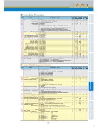
![─ 32 ─
Function Settings
■Function Settings
0 : Disable
1 : Enable (Process control, normal operation)
2 : Enable (Process control, inverse operation)
3 : Enable (Dancer control)
0 : / keys on keypad
1 : PID process command 1 (Analog input terminals [12], [C1], and [V2])
3 : UP/DOWN
4 : Command via communications link
0.000 to 30.000 times
0.0 to 3600.0 s
0.00 to 600.00 s
0.0 to 900.0 s
0.0 to 500.0 Hz
0 to 60 s
0% to 200%
0 : Absolute-value alarm
1 : Absolute-value alarm (with Hold)
2 : Absolute-value alarm (with Latch)
3 : Absolute-value alarm (with Hold and Latch)
4 : Deviation alarm
5 : Deviation alarm (with Hold)
6 : Deviation alarm (with Latch)
7 : Deviation alarm (with Hold and Latch)
-100% to 100%
-100% to 100%
0.0: Disable; 1.0 to 500.0 Hz
0 to 60 s
0.0 to 500.0 Hz
-150% to 150%; 999: Depends on setting of F15
-150% to 150%; 999: Depends on setting of F16
1% to 50%
0 : Keep inverter operation (Stop due to alarm)
1 : Automatically switch to commercial-power operation
0.00 to 5.00 s
-100% to 0% to 100%
0: Disable switching PID constant
1% to 100% (Manually set value)
0.000 to 30.000 times
0.0 to 3600.0 s
0.00 to 600.00 s
0 to 3
bit 0: PID output characteristics
0: Plus (add), 1: Minus (subtract)
bit 1: Select compensation factor of output ratio
0 = Ratio (relative to the main setting)
1 = Speed command (relative to maximum frequency)
0% to 300%
0.0 to 25.0 Hz
0.0 to 5.0 s
0.0 to 25.0 Hz
0.0 to 5.0 s
0% to 300%
0 : Detected speed
1 : Commanded speed
×
×
○
○
○
○
○
○
○
○
○
○
○
○
○
○
○
○
×
○
○
○
○
○
○
×
○
○
○
○
○
○
○
○
○
○
○
○
○
○
○
○
○
○
○
○
○
○
○
○
○
○
○
○
○
○
○
○
○
○
○
○
○
○
○
○
○
○
○
○
○
○
○
○
○
○
○
○
○
○
○
○
○
○
○
○
○
○
○
○
○
○
○
○
○
○
○
○
○
○
○
○
○
○
○
○
○
○
○
○
○
○
○
○
○
○
○
○
○
○
○
○
○
○
○
○
○
○
○
○
○
○
0
0
0.100
0.0
0.00
0.5
0.0
0
200
0
100
0
0.0
30
0.0
999
999
1
0
0.10
0
0
0.100
0.0
0.00
0
100
1.0
1.0
1.0
1.0
100
0
●J codes: Application Functions 1
(Mode selection)
(Remote command SV)
P (Gain)
I (Integral time)
D (Differential time)
(Feedback filter)
(Pressurization starting frequency)
(Pressurizing time)
(Anti reset windup)
(Select alarm output)
(Upper level alarm (AH))
(Lower level alarm (AL))
(Stop frequency for slow flowrate)
(Slow flowrate level stop latency)
(Starting frequency)
(Upper limit of PID process output)
(Lower limit of PID process output)
(Duty)
(Speed command filter)
(Dancer reference position)
(Detection width of dancer position deviation)
P (Gain) 2
I (Integral time) 2
D (Differential time) 3
(PID control block selection)
(Brake-OFF current)
(Brake-OFF frequency/speed)
(Brake-OFF timer)
(Brake-ON frequency/speed)
(Brake-ON timer)
(Brake-OFF torque)
(Speed selection)
PID Control
Dew Condensation Prevention
Commercial Power Switching
Sequence
PID Control
Braking Signal
0.000 to 5.000 s
0.000 to 0.100 s
0.1 to 200.0 times
0.001 to 1.000 s
0.000 to 0.100 s
0.000 to 5.000 s
0.000 to 0.100 s
0.1 to 200.0 times
0.001 to 1.000 s
0.000 to 0.100 s
0 : Pulse train sign/Pulse train input
1 : Forward rotation pulse/Reverse rotation pulse
2 : A/B phase with 90 degree phase shift
20 to 60000
1 to 9999
1 to 9999
0.0% to 50.0%
0.00 to 10.00 s
0 : Continue to run
1 : Stop running with alarm 1
2 : Stop running with alarm 2
0 : Not permit at startup
1 : Permit at startup
0.000 to 1.000 s
Speed control 1
Speed control
Feedback Input
Speed Agreement/PG Error
PG Error Processing
Zero Speed Control
ASR Switching Time
○
◎
◎
◎
○
○
◎
◎
◎
○
×
×
×
×
○
○
×
×
○
○
○
○
○
○
○
○
○
○
○
○
○
○
○
○
○
○
○
○
×
×
×
×
×
×
×
×
×
×
×
×
×
×
×
×
×
×
×
○
○
○
○
○
○
○
○
○
○
○
○
○
○
○
○
○
○
○
0.020
0.005
10.0
0.100
0.002
0.020
0.005
10.0
0.100
0.002
2
1024
1
1
10.0
0.50
2
0
0.000
●d codes: Application Functions 2
(Speed command filter)
(Speed detection filter)
P (Gain)
I (Integral time)
(Output filter)
(Jogging)
(Speed command filter)
(Speed detection filter)
P (Gain)
I (Integral time)
(Output filter)
(Pulse input property)
(Encoder pulse resolution)
(Pulse count factor 1)
(Pulse count factor 2)
(Hysteresis width)
(Detection timer)
Code Name Data setting range
Default
setting
Drive control
V/f Vector
Changewhen
running
Data
copying
Code Name Data setting range
Default
setting
Drive control
V/f Vector
Changewhen
running
Data
copying](https://image.slidesharecdn.com/catalog-frenic-mega-fuji-electric-160426030600/85/Catalog-bi-n-t-n-Frenic-Mega-Fuji-Electric-Beeteco-com-33-320.jpg)
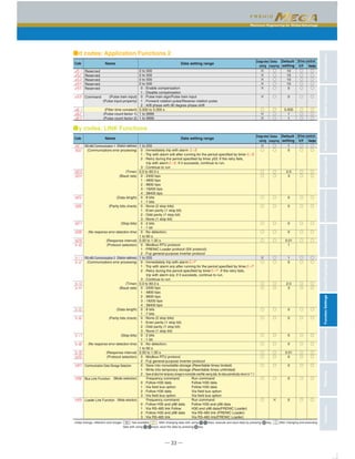
![─ 34 ─
External Dimensions(Basic Type, EMC Filter Built-in Type)
●Inverter main body(0.4kW) ●Inverter main body(0.75kW)
●Inverter main body(1.5kW) ●Inverter main body(2.2・3.7kW)
110 130
41.517.4
82.98
8
17
3
130
246
260
77
48.67
96
8015
7 7
6
2 Ø6
110 145
17.4
97.98
8
32
130
246
260
77
7
96
8015
7 7
6
2 Ø6
3
56.5
63.6
77
114.1
97.988130
246
260
150
136
8017
2 Ø6
145
78.9
95
32
3
6
77
77
114.1
97.988130
246
260
150
136
8017
2 Ø6
145
78.9
95
32
3
6
77
[Unit:mm][Unit:mm]
[Unit:mm][Unit:mm]](https://image.slidesharecdn.com/catalog-frenic-mega-fuji-electric-160426030600/85/Catalog-bi-n-t-n-Frenic-Mega-Fuji-Electric-Beeteco-com-35-320.jpg)
![Maximum Engineering for Global Advantage
CharacteristicsModelVariationsStandardSpecificationsKeypadOperationsInverterSupportLoaderBasicWiringDiagramCommonSpecificationsExternalDimensionsFunctionSettingsWarrantyVariations
─ 35 ─
●Inverter main body(5.5kW) ●Inverter main body(7.5kW)
●Inverter main body(11kW) ●Inverter main body(15・18.5・22kW)
195220
196
80
12
27
12
10
90
10
2 Ø10
1111
130
238
260
138.7
145.728
9
88147.5
144.53
220
196
80
12
27
12
10
90
10
2 Ø10
1111
130
238
260
138.7
145.723
9
88147.5
144.53
195
220
196
80
12
27
12
10
90
10
2 Ø10
1111
130
238
260
138.7
145.728
9
88147.5
144.53
195
1212
27 80
226
250
2 Ø10
10
1111
130
378
400
104
150.488
18.7
15.5
12118.7
10
90
195
136.5
163.9
16.5
[Unit:mm][Unit:mm]
[Unit:mm][Unit:mm]](https://image.slidesharecdn.com/catalog-frenic-mega-fuji-electric-160426030600/85/Catalog-bi-n-t-n-Frenic-Mega-Fuji-Electric-Beeteco-com-36-320.jpg)
![─ 36 ─
External Dimensions(Basic Type, EMC Filter Built-in Type)
●Inverter main body(30kW)
●Inverter main body(37kW)
206
240
312
304 8(8)
512
530
288
40(40)
MAX326.2
MAX310.2
MAX261.3
255
140115
320
240
72.594.7
2 Ø10
10
12
25
303
500
530
550
(25)
(8)
4
(6.3)
4 M8
9
275
347
339 8(8)
5779
595
323
40
MAX361.2
355
275
MAX345.2
MAX276.3
270
115 155
328
565
595
25
12
615
214
(25)
(8)
4
(6.3)
4 M8
(40)
94.7 51.7
10
2 Ø10
Panel cutout dimensions
Panel cutout dimensions
[Unit:mm]
[Unit:mm]](https://image.slidesharecdn.com/catalog-frenic-mega-fuji-electric-160426030600/85/Catalog-bi-n-t-n-Frenic-Mega-Fuji-Electric-Beeteco-com-37-320.jpg)
![Maximum Engineering for Global Advantage
CharacteristicsModelVariationsStandardSpecificationsKeypadOperationsInverterSupportLoaderBasicWiringDiagramCommonSpecificationsExternalDimensionsFunctionSettingsWarrantyVariations
─ 37 ─
●Touch Panel
●Inverter main body(45・55kW)
* The inverter main body and the keypad are subject to change due to development.
339 8(8)
40
MAX361.2
355
275
MAX345.2
MAX276.3
270
115 155
433
690
720
25
12
740
319
(25)
(8)
4
(6.3)(40)
94.7 51.7
10
2 Ø10
347
7029
720
275
4 M8
Panel cutout dimensions
[Unit:mm]
[Unit:mm]
18.2
Rear view
Panel cutout
(10.5)
(128.5)
23
1
104.6
4.558
(80)
(9.5)61
2× 4
(16.98)
8.1
11.68
(53.8) 15.24
11.4
80
128.5
61 9.5
2×M3
(13.775)8.17
10.5104.6
15.08(14.615)](https://image.slidesharecdn.com/catalog-frenic-mega-fuji-electric-160426030600/85/Catalog-bi-n-t-n-Frenic-Mega-Fuji-Electric-Beeteco-com-38-320.jpg)
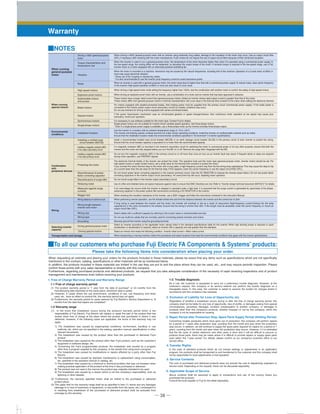
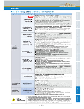
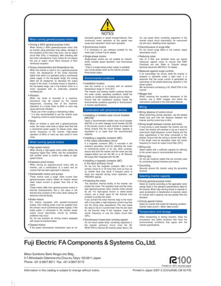

The document describes Fuji Electric's FRENIC-MEGA inverter. It has been developed to support a wide range of applications with improved performance, functionality, environmental awareness, and easy maintenance compared to previous models. Key features highlighted include improved acceleration and overload capabilities, enhanced response time, expanded brake circuit capacity, and various functions to accommodate different needs.


