Downloaded 23 times


![Specifications
Type (FRN E1S-2A/K/C)
Applicable motor rating [kW] (*1)
0.1
0.1
0.30
0.8
0.6
1.1 1.2 1.7 1.7 2.3 3.4 3.6 6.1 7.1
0.6 0.7 0.8 1.7 1.7 2.3 3.4 3.6 6.1 7.1
0.2
0.2
0.57
1.5
0.4
0.4
1.1
3.0
1.5
1.5
3.0
8.0
0.75
0.75
1.9
5.0
2.2
2.2
4.1
11
3.7
3.7
6.4
17
5.5
5.5
9.5
25
7.5
7.5
12
33
15
15
22
60
11
11
17
47
Applicable safety standards
Enclosure (IEC60529)
Cooling method
Weight / Mass [kg]
Rated capacity [kVA] (*2)
Rated voltage [V] (*3)
Rated current [A] (*4)
Overload capability
Rated frequency [Hz]
Phases, voltage, frequency
Voltage/frequency variations
Rated current [A] (*9)
(with DCR)
(without DCR)
Required power supply capacity [kVA] (*5)
Torque [%] (*6)
Torque [%] (*7)
DC injection braking
Braking transistor
Item Specifications
Type (FRN E1S-4A/K/C)
Applicable motor rating [kW] (*1)
0.4
0.4
1.1
0.75
0.75
1.9
1.5
1.5
2.8
2.2
2.2
4.1
3.7
3.7
6.8
5.5
5.5
9.9
7.5
7.5
13
11
11
18
15
15
22
0.85
1.7
0.6
1.6
3.1
1.1
3.0
5.9
2.0
4.4
8.2
2.9
7.3
13.0
4.9
10.6
17.3
7.4
14.4
23.2
10
21.1
33.0
15
28.8
43.8
20
1.5 2.5 3.7 5.5 13 18 24 30
204070100
9.0
Applicable safety standards
Enclosure (IEC60529)
Cooling method
Weight / Mass [kg]
Rated capacity [kVA] (*2)
Rated voltage [V] (*3)
Rated current [A] (*4)
Overload capability
Rated frequency [Hz]
Phases, voltage, frequency
Voltage/frequency variations
Rated current [A] (*9)
(with DCR)
(without DCR)
Required power supply capacity [kVA] (*5)
Torque [%] (*6)
Torque [%] (*7)
DC injection braking
Braking transistor
Item Specifications
(1.4)(0.7)
0.57
1.1
0.2
0.93
1.8
0.3
1.6
3.1
0.6
3.0
5.3
1.1
5.7
9.5
2.0
8.3
13.2
2.9
14.0
22.2
4.9
21.1
31.5
7.4
28.8
42.7
10
42.2
60.7
15
57.6
80.1
20
(4.2)
150 100 70 2040
(2.5) (10)(7.0) (23.5)(16.5) (31) (57)(44)
150% of rated current for 1min, 200% - 0.5s
50, 60Hz
Three-phase, 200 to 240V, 50/60Hz
Voltage: +10 to -15% (Voltage unbalance (*8): 2% or less) Frequency: +5 to -5%
Three-phase, 380 to 480V, 50/60Hz
Voltage: +10 to -15% (Voltage unbalance (*8): 2% or less) Frequency: +5 to -5%
Built-in
UL508C, C22.2No.14, EN50178:1997
IP20, UL open type
Natural cooling Fan cooling
Starting frequency: 0.1 to 60.0Hz, Braking time: 0.0 to 30.0s, Braking level: 0 to 100% of rated current
150-
UL508C, C22.2No.14, EN50178:1997
IP20, UL open type
Natural cooling Fan cooling
Starting frequency: 0.1 to 60.0Hz, Braking time: 0.0 to 30.0s, Braking level: 0 to 100% of rated current
150
Built-in
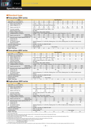
■Three-phase 200V series
■Three-phase 400V series
●Standard type
(*1) Fuji's 4-pole standard motor
(*2) Rated capacity is calculated by assuming the output rated voltage as 220V for three-phase 200V series and 440V for three-phase 400V series.
(*3) Output voltage cannot exceed the power supply voltage.
(*4) When setting the carrier frequency (F26) to 3 kHz or less. Use the current ( ) or below when the carrier frequency setting is higher than 4kHz and continuously operating at 100%.
(*5) Obtained when a DC REACTOR is used.
(*6) Average braking torque obtained when reducing the speed from 60Hz with AVR control OFF (Varies with the efficiency of the motor.)
(*7) Average braking torque obtained by use of external braking resistor (standard type available as option)
(*8) Voltage unbalance [%] =
Max voltage [V] - Min voltage [V]
x 67 (IEC 61800-3)
Three-phase average voltage [V]
If this value is 2 to 3%, use AC REACTOR (ACR: option).
(*9) The value is calculated on assumption that the inverter is connected with a power supply capacity of 500kVA (or 10 times the inverter capacity if the inverter capacity exceeds 50kVA) and %X is 5%.
Three-phase 380V to 480V (with AVR function)
150% of rated current for 1min, 200% - 0.5s
50, 60Hz
Three-phase 200V to 240V (with AVR function)
OutputratingsInputpowerBrakingOutputratingsInputpowerBraking
-
Type (FRN E1S-7A/K/C)
Applicable motor rating [kW] (*1)
0.1
0.1
0.3
0.6 0.6 0.7 0.9 1.8 2.4
1.1
1.8
0.3
2.0
3.3
0.4
3.5
5.4
0.7
6.4
9.7
1.3
11.6
16.4
2.4
17.5
24.8
3.5
0.8
(0.7) (1.4) (2.5) (4.2) (7.0) (10)
1.5
150 100
Built-in
Fan cooling
70 40
8.0 113.0 5.0
0.2
0.2
0.57
0.4
0.4
1.1
0.75
0.75
1.9
1.5
1.5
3.0
2.2
2.2
4.1
Applicable safety standards
Enclosure (IEC60529)
Cooling method
Weight / Mass [kg]
Rated capacity [kVA] (*2)
Rated voltage [V] (*3)
Rated current [A] (*4)
Overload capability
Rated frequency [Hz]
Phases, voltage, frequency
Voltage/frequency variations
Rated current [A] (*9)
(with DCR)
(without DCR)
Required power supply capacity [kVA] (*5)
Torque [%] (*6)
Torque [%] (*7)
DC injection braking
Braking transistor
Item Specifications
■Single-phase 200V series
150% of rated current for 1min, 200% - 0.5s
50, 60Hz
Single-phase, 200 to 240V, 50/60Hz
Voltage: +10 to -10%, Frequency: +5 to -5%
UL508C, C22.2No.14, EN50178:1997
IP20, UL open type
Natural cooling
Starting frequency: 0.1 to 60.0Hz, Braking level: 0 to 100% of rated current, Braking time: 0.0 to 30.0s
150
Three-phase 200V to 240V (with AVR function)
OutputratingsInputpowerBraking](https://image.slidesharecdn.com/frenic-multihpc2-150320034428-conversion-gate01/85/Catalog-Frenic-MULTI-www-haophuong-com-8-320.jpg)
![Type (FRN E1E-7A/K/C)
Nominal applied motor [kW] (*1)
0.1
0.1
0.3
0.7 0.7 0.8 1.3 2.5 3.0
1.1
1.8
0.3
2.0
3.3
0.4
3.5
5.4
0.7
6.4
9.7
1.3
11.6
16.4
2.4
17.5
24.8
3.5
0.8
(0.7) (1.4) (2.5) (4.2) (7.0) (10)
1.5
150 100
Built-in
Fan cooling
70 40
8.0 113.0 5.0
0.2
0.2
0.57
0.4
0.4
1.1
0.75
0.75
1.9
1.5
1.5
3.0
2.2
2.2
4.1
Applicable safety standards
Enclosure
Cooling method
EMC standard Emission
compliance Immunity
Weight / Mass [kg]
Rated capacity [kVA] (*2)
Rated voltage [V] (*3)
Rated current [A] (*4)
Overload capability
Rated frequency [Hz]
Phases, voltage, frequency
Voltage/frequency variations
Rated current [A] (*8)
(with DCR)
(without DCR)
Required power supply capacity [kVA] (*5)
Torque [%] (*6)
DC injection braking
Braking transistor
Item Specifications
■Single-phase 200V series(0.1 to 2.2kW)
150% of rated current for 1min or 200% of rated current for 0.5s
50, 60Hz
Single-phase, 200 to 240V, 50/60Hz
Voltage: +10 to -10%, Frequency: +5 to -5%
UL508C, C22.2No.14 (pending),EN50178:1997
IP20 (IEC60529)/UL open type (UL50)
Natural cooling
Class 1A (EN55011:1998/A1:1999)
2nd Env. (EN61800-3:1996/A11:2000)
Starting frequency: 0.0 to 60.0Hz, Braking time: 0.0 to 30.0s, Braking level: 0 to 100%
Three-phase 200 to 240V (with AVR)
OutputratingsInputratingsBraking
Type (FRN E1E-2A/K/C)
Nominal applied motor [kW] (*1)
0.1
0.1
0.30
0.8
0.7
1.5 1.6 2.5 2.5 3.0 TBD TBD TBD TBD
0.7 0.8 0.9 2.4 2.4 2.9 TBD TBD TBD TBD
0.2
0.2
0.57
1.5
0.4
0.4
1.1
3.0
1.5
1.5
3.0
8.0
0.75
0.75
1.9
5.0
2.2
2.2
4.1
11
3.7
3.7
6.4
17
5.5
5.5
9.5
25
7.5
7.5
12
33
15
15
22
60
11
11
17
47
Applicable safety standards
Enclosure
Cooling method
EMC standard Emission
compliance Immunity
Weight / Mass [kg]
Rated capacity [kVA] (*2)
Rated voltage [V] (*3)
Rated current [A] (*4)
Overload capability
Rated frequency [Hz]
Phases, voltage, frequency
Voltage/frequency variations
Rated current [A] (*8)
(with DCR)
(without DCR)
Required power supply capacity [kVA] (*5)
Torque [%] (*6)
DC injection braking
Braking transistor
Item Specifications
Type (FRN E1E-4A/K/C)
Nominal applied motor [kW] (*1)
0.4
0.4
1.1
0.75
0.75
1.9
1.5
1.5
2.8
2.2
2.2
4.1
3.7
3.7
6.8
5.5
5.5
9.9
7.5
7.5
13
11
11
18
15
15
22
0.85
1.7
0.6
1.6
3.1
1.1
3.0
5.9
2.0
4.4
8.2
2.9
7.3
13.0
4.9
10.6
17.3
7.4
14.4
23.2
10
21.1
33.0
15
28.8
43.8
20
1.5 2.5 3.7 5.5 13 18 24 30
204070100
9.0
Applicable safety standards
Enclosure
Cooling method
EMC standard Emission
compliance Immunity
Weight / Mass [kg]
Rated capacity [kVA] (*2)
Rated voltage [V] (*3)
Rated current [A] (*4)
Overload capability
Rated frequency [Hz]
Phases, voltage, frequency
Voltage/frequency variations
Rated current [A] (*8)
(with DCR)
(without DCR)
Required power supply capacity [kVA] (*5)
Torque [%] (*6)
DC injection braking
Braking transistor
Item Specifications
(1.4)(0.7)
0.57
1.1
0.2
0.93
1.80
0.30
1.6
3.1
0.6
3.0
5.3
1.1
5.7
9.5
2.0
8.3
13.2
2.9
14.0
22.2
4.9
21.1
31.5
7.4
28.8
42.7
10
42.2
60.7
15
57.6
80.1
20
(4.2)
150 100 70 2040
(2.5) (10)(7.0) (23.5)(16.5) (31) (57)(44)
150% of rated current for 1min or 200% of rated current for 0.5s
50, 60Hz
Three-phase, 200 to 240V, 50/60Hz
Voltage: +10 to -15% (Voltage unbalance : 2% or less (*7)) Frequency: +5 to -5%
Three-phase, 380 to 480V, 50/60Hz
Voltage:+10 to -15% (Voltage unbalance: 2% or less (*7)), Frequency: +5 to -5%
Built-in
UL508C, C22.2No.14(pending), EN50178:1997
IP20(IEC60529)/UL open type(UL50)
Natural cooling
Class 1A (EN55011:1998/A1:1999)
2nd Env. (EN61800-3:1996/A11:2000)
Fan cooling
2nd Env. (EN61800-3:1996+A11:2000)
Starting frequency: 0.0 to 60.0Hz, Braking time: 0.0 to 30.0s, Braking level: 0 to 100%
UL508C, C22.2No.14 (pending), EN50178:1997
IP20 (IEC60529)/UL open type (UL50)
Natural cooling
Class 1A (EN55011:1998/A1:1999)
2nd Env. (EN61800-3:1996/A11:2000)
Fan cooling
2nd Env. (EN61800-3:1996+A11:2000)
Starting frequency: 0.0 to 60.0Hz, Braking time: 0.0 to 30.0s, Braking level: 0 to 100%
Built-in
EMC filter built-in type
■Three-phase 200V series(0.1 to 15kW)
■Three-phase 400V series (0.4 to 15kW)
●Semi-standard type
*1) Fuji's 4-pole standard motor
*2) Rated capacity is calculated by regarding the output rated voltage as 220V for three-phase 200V series.
*3) Output voltage cannot exceed the power supply voltage.
*4) The load shall be reduced so that the continuous operating current is the rated current in parenthesis or less if the carrier frequency is set to 4kHz or above.
*5) Obtained when a DC REACTOR is used.
*6) Average braking torque when a motor of no load decelerates.(Varies with the efficiency of the motor.)
*7) Voltage unbalance [%] =
Max. voltage [V] - Min. voltage [V]
x 67 (IEC61800-3(5.2.3))
Three-phase average voltage [V]
If this value is 2 to 3%, use an AC REACTOR.
*8) The currents are calculated on the condition that the inverters are connected to power supply of 500kVA, %X=5%.
Three-phase 380 to 480V (with AVR)
150% of rated current for 1min or 200% of rated current for 0.5s
50, 60Hz
Three-phase 200 to 240V (with AVR)
OutputratingsInputratingsBrakingOutputratingsInputratingsBraking
Specifications](https://image.slidesharecdn.com/frenic-multihpc2-150320034428-conversion-gate01/85/Catalog-Frenic-MULTI-www-haophuong-com-9-320.jpg)

![Displays the cause of trip by codes.
• (Overcurrent during acceleration) • (Overcurrent during deceleration) • (Overcurrent at constant speed)
• (Input phase loss) • (Undervoltage) • (Output phase loss)
• (Overvoltage during acceleration) • (Overvoltage during deceleration) • (Overvoltage at constant speed)
• (Overheating of the heat sink) • (External alarm) • (Inverter overheat)
• (Motor protection (PTC thermistor)) • (Motor 1 overload) • (Motor 2 overload)
• (Inverter overload) • (Overheating of braking resistor) • (PG disconnection)
• (Memory error) • (Keypad communication error) • (CPU error)
• (Optional communication error) • (Option error) • (Operation error)
• (Tuning error) • (RS-485 communication error) • (Data save error due to undervoltage)
• (RS485 communication error (option))• (Power LSI error) • (Simulation error)
Altitude [m]
Lower than 1,000
1,001 to 2,000
2,001 to 3,000
Output decrease
None
Decreases
Decreases*
■ Feedback value
• Analog input from terminal 12, C1 (V2) : 0 to ±10V DC/0 to ±100%
• Analog input (terminal C1) : 4 to 20mA DC/0 to 100%
■ Accessory functions
• Alarm output (absolute value alarm, deviation alarm) • Normal operation/inverse operation
• PID output limiter • Anti-reset wind-up function • Integration reset/hold
Operation begins at a preset pick-up frequency to search for the motor speed to start an idling motor without stopping it.
The output voltage is controlled to minimize the total sum of the motor loss and inverter loss at a constant speed.
The motor parameters are automatically tuned.
Detects inverter internal temperature and stops cooling fan when the temperature is low.
The motor loss increases during deceleration to reduce the load energy regenerating at the inverter
to avoid an trip upon mode selection.
When the torque calculation value exceeds the limit level set for the inverter during deceleration, the output
frequency is automatically controlled and the deceleration time automatically extends to avoid an trip.
Trip may occur due to load conditions.
An external output is issued in a transistor output signal.
An external output is issued in a transistor output signal.
Waiting time before resetting and the number
of retry times can be set.
-10 to 40˚C when inverters are installed side by side without clearance.
* If the altitude exceeds 2,000m, insulate
the interface circuit from the main power
supply to conform to the Low Voltage
Directives.
Mode that the motor rotates and mode that the motor does not rotate can be selected.
PID control
Pick-up
Automatic deceleration
Deceleration characteristic
Automatic energy-saving operation
Overload Prevention Control
Auto-tuning
Cooling fan ON/OFF control
Secondary motor setting
Universal DI
Universal AO
Speed control
Positioning control
Rotation direction control
Running/stopping
Life early warning
Cumulative run hours
I/O check
Power monitor
Trip mode
Running or trip mode
Overcurrent protection
Short circuit protection
Grounding fault protection
Overvoltage protection
Undervoltage
Input phase loss
Output phase loss
Overheating
Overload
Stall prevention
Momentary power failure
protection
Retry function
Command loss detection
Installation location
Ambient temperature
Ambient humidity
Altitude
Vibration
Electronic thermal
PTC thermistor
Overload early warning
Ambient temp.
Ambient humidity
The output frequency is automatically reduced to suppress the overload protection trip o inverter
caused by an increase in the ambient temperature, operation frequency, motor load or the like.
• One inverter can be used to control two motors by switching (switching is not available while a motor is running). Base
frequency, rated current, torque boost, electronic thermal, slip compensation can be set as data for the secondary motor.
• The second motor constants can be set in the inverter. (Auto-tuning possible)
The presence of digital signal in a device externally connected to the set terminal can be sent to the master controller.
The output from the master controller can be output from the terminal FM.
The motor speed can be detected with the pulse encoder and speed can be controlled.
Only one program can be executed by setting the number of pulses to the stop position and deceleration point.
Select either of reverse prevention or forward rotation prevention.
The life early warning of the main circuit capacitors, capacitors on the PC boards and the cooling fan can be displayed.
The cumulative motor running hours, cumulative inverter running hours and cumulative watt-hours can be displayed.
Displays the input signal status of the inverter.
Displays input power (momentary), accumulated power, electricity cost (accumulated power x displayed coefficient).
Trip history: Saves and displays the last 4 trip codes and their detailed description.
The inverter is stopped upon an overcurrent caused by an overload.
The inverter is stopped upon an overcurrent caused by a short circuit in the output circuit.
The inverter is stopped upon an overcurrent caused by a grounding fault in the output circuit.
An excessive DC link circuit voltage is detected to stop the inverter.
Stops the inverter by detecting voltage drop in DC link circuit.
Stops or protects the inverter against input phase loss.
Detects breaks in inverter output wiring at the start of running and during running, stopping the inverter output.
The inverter is stopped upon the temperature of the heat sink of the inverter or the temperature of the
switching element calculated from the output current.
The temperature of the heat sink of the inverter or that inside the inverter unit is detected to stop the inverter, upon a failure or overload of the cooling fan.
The inverter is stopped upon an electronic thermal function setting to protect the motor.
A PTC thermistor input stops the inverter to protect the motor.
Warning signal can be output based on the set level before the inverter trips.
The output frequency decreases upon an output current exceeding the limit during acceleration or constant speed operation, to avoid overcurrent trip.
• A protective function (inverter stoppage) is activated upon a momentary power failure for 15msec or longer.
• If restart upon momentary power failure is selected, the inverter restarts upon recovery of the voltage within the set time.
A loss (broken wire, etc.) of the frequency command is detected to output an alarm and continue
operation at the preset frequency (set at a ratio to the frequency before detection).
Shall be free from corrosive gases, flammable gases, oil mist, dusts, and direct sunlight.
(Pollution degree 2 (IEC60664-1)). Indoor use only.
-10 to +50˚C
5 to 95% RH (without condensation)
When the motor is tripped and stopped, this function automatically resets the tripping state and
restarts operation.
• Speed monitor, output current [A], output voltage [V], torque calculation value, input power [kW],
PID reference value, PID feedback value, PID output, load factor, motor output, period for timer operation [s]
◆Select the speed monitor to be displayed from the following:
Output frequency [Hz], Output frequency 1 [Hz] (before slip compensation),
Output frequency 2 (after slip compensation) [Hz],
Motor speed (set value) [r/min],
Motor speed [r/min], Load shaft speed (set value) [r/min],
Load shaft speed (r/min),
Line speed (set value), Line speed (r/min)
3mm (vibration width): 2 to less than 9Hz, 9.8m/s2
: 9 to less than 20Hz, 2m/s2
: 20 to less than 55Hz, 1m/s2
: 55 to less than 200Hz
-25 to +65˚C
5 to 95%RH (without condensation)
3-phase 200V / 400V DC, Single-phase 200V/400V DC
3-phase 400V / 800V D
3-phase 200V / 200V DC, Single-phase 200V/400V DC
3-phase 400V / 400V DC
The protective function can be canceled with function code 99.
The protective function can be canceled with function code 99.
Thermal time constant can be adjusted (0.5 to 75.0min.)
E61 to E63
J01 to J06
J10 to J19
H09, H13, H17
H69, F08
H71
F37, F09
H70
P04
E43
E48
E52
F14
H98
H98
H43
F10 to F12, P99
H26, H27
H12
H13 to H16
F14
H04, H05
E65
F10, F12, E34,
E35, P99
■ Process command
• Key operation ( and keys) : 0 to 100%
• Analog input (terminal 12, C1 (V2)) : 0 to ±10V DC/0 to ±100%
• Analog input (terminal C1) : 4 to 20mA DC/0 to 100%
• UP/DOWN (digital input) : 0 to 100%
• Communication (RS-485, bus option) : 0 to 20000/0 to 100%
Control with PID regulator or dancer controller.
H06
When the PG interface card (optional) Is installed.
When the PG interface card (optional) Is installed.
Item Explanation Related
function codeRemarks
IndicationControlProtection
MotorprotectionStorage
Environment
Specifications](https://image.slidesharecdn.com/frenic-multihpc2-150320034428-conversion-gate01/85/Catalog-Frenic-MULTI-www-haophuong-com-11-320.jpg)


![Main circuit
Basic Wiring Diagram
●Wiring diagram
M
MCCB
or
ELCB
(Note 2)
(Note 3)
Power
Three-phase/
single-phase
200 to 240V,
50/60Hz
or three-phase
390 to 480V,
50/60Hz
MC
MCCB
or
ELCB
(Note 2)
(Note 3)
Power
Three-phase/
single-phase
200 to 240V,
50/60Hz
or three-phase
390 to 480V,
50/60Hz
MC
DCR
P1
DBR
(Note 4)
Motor
L1/R
P1
U
V
W
Grounding terminal
MCCB: Molded-case circuit breaker
ELCB: Earth-leakage circuit breaker
MC: Magnetic contactor
DCR: DC reactor
DBR: Braking resistor
C1
C1
SW8
SW8
FMA
FMA
FMP
FMP
SW6
SW6
SW1
SW1
V2
V2
SW7
SW7
PTC
SW3
SW3
30A
30B
30C
30
SINK
SOURCE
RS485 port
(option)
(Note 1)
P DB
(CM)
(THR)
P(+)
P(+)
N(-)DB
[12]
[13]
[11]
[11]
[FM]
[C1]
<Y1>
<Y2>
<CMY>
(FWD)
(REV)
(CM)
(X1)
(X2)
(X3)
(X4)
(X5)
(CM)
(PLC)
Alarm output
(for any fault)
Transistor input
L2/S
L3/T
GGGrounding terminal
Control circuit
Main circuit
M
DCR
P1
DBR
(Note 4)
Motor
L1/R
P1
U
V
W
Grounding terminal
MCCB: Molded-case circuit breaker
ELCB: Earth-leakage circuit breaker
MC: Magnetic contactor
DCR: DC reactor
DBR: Braking resistor
PTC
Meter
Analog
input
Digital input
30A
30B
30C
30
SINK
SOURCE
RS485 port
(option)
(Note 1)
P DB
(CM)
(THR)
P(+)
P(+)
N(-)DB
[12]
[13]
[11]
[11]
[FM]
[C1]
<Y1>
<Y2>
<CMY>
(FWD)
(REV)
(CM)
(X1)
(X2)
(X3)
(X4)
(X5)
(CM)
(PLC)
Alarm output
(for any fault)
Transistor input
L2/S
L3/T
GGGrounding terminal
Potentiometer power supply
Voltage input for setting
DC0 to ±10V
Current/voltage input
for setting
DC +4 to 20 mA/DC0 to 10V
(Note 5)
1
2
3
(Note 6)
(+)
(-)
■Keypad operation
■Run/Stop operation and frequency setting on the keypad
[Wiring procedure]
(1) Wire the inverter main power circuit.
[Operation method]
(1) Run/Stop: Press or key.
(2) Setting frequency: Set the frequency with and keys.
Note1: When connecting a DC REACTOR (DCR option), remove the
jumper bar from across the terminals [P1] and [P (+)].
Note2: Install a recommended molded-case circuit breaker (MCCB) or an
earth-leakage circuit-breaker (ELCB) (with an overcurrent
protection function) in the primary circuit of the inverter to protect
wiring. At this time, ensure that the circuit breaker capacity is
equivalent to or lower than the recommended capacity.
Note3: Install a magnetic contactor (MC) for each inverter to separate the
inverter from the power supply, apart from the MCCB or ELCB,
when necessary.
Connect a surge killer in parallel when installing a coil such as the
MC or solenoid near the inverter.
Note4: (THR) function can be used by assigning code "9" (external alarm)
to any of the terminals X1 to X5, FWD or REV (function code; E01
to E05, E98, or E99).
■Operation by external signal inputs
■Run/Stop operation and frequency setting through external signals
[Wiring procedure]
(1) Wire both the inverter main power circuit and control circuit.
(2) Set (external signal) at function code . Next, set (voltage input
(terminal 12) (0 to +10V DC)), (current input (terminal C1) (+4 to
20mA DC)), or other value at function code .
[Operation method]
(1) Run/Stop: Operate the inverter across terminals FDW and CM short-
circuited, and stop with open terminals.
(2) Frequency setting: Voltage input (0 to +10V DC), current input (+4 to
20mA DC)
Note1: When connecting a DC REACTOR (DCR option), remove the
jumper bar from across the terminals [P1] and [P (+)].
Note2: Install a recommended molded-case circuit breaker (MCCB) or an
earth-leakage circuit-breaker (ELCB) (with an overcurrent
protection function) in the primary circuit of the inverter to protect
wiring. At this time, ensure that the circuit breaker capacity is
equivalent to or lower than the recommended capacity.
Note3: Install a magnetic contactor (MC) for each inverter to separate the
inverter from the power supply, apart from the MCCB or ELCB,
when necessary.
Connect a surge killer in parallel when installing a coil such as the
MC or solenoid near the inverter.
Note4: (THR) function can be used by assigning code "9" (external alarm)
to any of the terminals X1 to X5, FWD or REV (function code; E01
to E05, E98, or E99).
Note5: Frequency can be set by connecting a frequency-setting device
(external potentiometer) between the terminals 11, 12 and 13
instead of inputting a voltage signal (0 to +10V DC, 0 to +5V DC
or +1 to +5V DC) between the terminals 12 and 11.
Note 6: For the control signal wires, use shielded or twisted wires.
Ground the shielded wires. To prevent malfunction due to noise,
keep the control circuit wiring away from the main circuit wiring as
far as possible (recommended: 10cm or more). Never install them
in the same wire duct.
When crossing the control circuit wiring with the main circuit wiring,
set them at right angles.
The following diagram is for reference only. For detailed wiring diagrams, refer to the instruction manual.
Control circuit
Keypad
Operations
Basic
WiringDiagram](https://image.slidesharecdn.com/frenic-multihpc2-150320034428-conversion-gate01/85/Catalog-Frenic-MULTI-www-haophuong-com-17-320.jpg)

![■Terminal Functions
Symbol Terminal name Functions Remark
Related
function
code
(FMA)
(FMP)
Connectable impedance (Minimum
impedance: 5kW In the (0 to +10V DC)
In case of voltage output, up to two analog
voltmeters (0 to 10V DC, input impedance:
10kW) can be connected.Gain adjustment
range: 0 to 300%
Up to two analog voltmeters
(0 to10V DC, input impedance:
10kΩ) can be connected.
(Driven at average voltage)
Max. voltage: 27V DC
Max. current: 50mA
Leak current: 0.1mA max.
ON voltage: within 2V (at 50mA)
• Short circuit across terminals CM and CMY to use.
• Same terminal as digital input PLC terminal
Detection width: 0 to 10.0 [Hz]
Operation level: 0.0 to 400.0 [Hz]
Hysteresis width: 0.0 to 400.0 [Hz]
The terminal is isolated from terminals 11 and CM.
Contact capacity: 250V AC,0.3A,
cosφ=0.3, +48V DC, 0.5A
Power (+5V) is supplied to the
keypad.
A monitor signal of analog DC voltage between 0 to +10V DC) can be output
for the item selected from the following:
• Output frequency 1 (before slip compensation) • Output frequency 2 (after slip
compensation) • Output current • Output voltage • Output torque • Load factor. •
Power consumption • PID feedback value (PV) • DC link circuit voltage • Universal
AO. • Motor output • Analog output test. • PID command (SV) • PID output (MV)
One of the following items can be output in a pulse frequency.
• Output frequency 1 (before slip compensation) • Output frequency 2 (after slip
compensation) • Output current • Output voltage • Output torque • Load factor.o
Power consumption • PID feedback value (PV) • DC link circuit voltage • Universal
AO • Motor output • Analog output test • PID command (SV) • PID output (MV)
The following functions can be set at terminals Y1 or Y2 for signal output.
• The setting of "short circuit upon active signal output" or "open upon active
signal output" is possible.
• Sink/source support (switching unnecessary)
An ON signal is output at output frequencies above a preset detection level.
The signal is deactivated if the output frequency falls below the detection level.
The OFF signal is output when the inverter is running in drive mode and the
ON signal is output in the braking mode or stopped state.
If more than 20ms elapse while one of the following operations is operating:
current limiter for the inverter, automatic deceleration operation or torque limiter.
• A no-voltage contact signal (1c) is issued when the inverter is stopped due to an alarm.
• Multi-purpose relay output; signals similar to above-mentioned signals Y1 to Y2 can be selected.
• An alarm output is issued upon either excitation or no excitation according to selection.
One of the following protocols can be selected.
• Protocol exclusively for keypad (default selection)
• Modbus RTU
• Fuji's special inverter protocol
• SX protocol for PC loader
Analog monitor
Pulse monitor
Transistor output
power
Transistor output 1
Transistor output 2
Inverter running
Inverter output on
Speed/freq. arrival
Speed/freq. detection
Undervoltage detection
Torque polarity
detection
Inverter output limit (limit on current)
Auto-restarting
Overload early warning (motor)
Operation ready output
Motor 2 switching
Retry in action
Heat sink overheat early warning
Frequency arrival 2
Inverter output limit
Lifetime alarm
Command loss detection
Overload preventive control
Current detection
Current detection 2
PID alarm output
Brake signal
Alarm relay output (for any fault)
Transistor output common
Alarm relay output
(for any fault)
RJ-45 connector for
connection of keypad
Power supply for a transistor output load. (24V DC 50mA DC Max)
An ON signal is output when the inverter runs at higher than the starting frequency.
A signal is issued when the inverter runs at smaller than the starting frequency or when DC braking is in action.
An active signal is issued when the output frequency reaches the set frequency.
The signal is output when the inverter stops because of undervoltage.
The signal is output when the inverter is limiting the current.
The signal is output during auto restart operation (after momentary power failure and until completion of restart).
The signal is output when the electronic thermal relay value is higher than the preset alarm level.
A signal is issued if preparation for inverter operation is completed.
The motor switching signal (M2/M1) is input and the ON signal is output when the motor 2 is selected.
The signal is output during an active retry.
An early warning signal is issued before the heat sink trips due to overheat.
The signal is output when the time set in E29 elapses after the frequency arrival signal (FAR) is output.
Outputs alarm signal according to the preset lifetime level.
A loss of the frequency command is detected.
The signal is output when the overload control is activated.
The signal is output when a current larger than the set value has been detected for the timer-set time.
The signal is output when a current larger than the set value 2 has been detected for the timer-set time.
An absolute value alarm or deviation alarm under PID control is issued as a signal.
The signal for enabling or releasing the brake is output.
An alarm relay output (for any fault) signal is issued as a transistor output signal.
Common terminal for transistor output
F29 to
F31
F29,
F31,
F33
E20
E21
E22
E30
E31
E32
F43, F44
F14
F10 to F12
H04, H05
E29
F41 to F44
H69
H42,H43,H98
E65
H70
E34, E35
E37, E38
J11 to J13
J68 to J72
E27
FM
(PLC)
Y1
Y2
CMY
30A,30B,30C
-
(RUN)
(RUN2)
(FAR)
(FDT)
(LV)
(B/D)
(IOL)
(IPF)
(OL)
(RDY)
(SWM2)
(TRY)
(OH)
(FAR2)
(IOL2)
(LIFE)
(REF OFF)
(OLP)
(ID)
(ID2)
(PID-ALM)
(BRKS)
(ALM)
H30
y01 to y20
y98,y99
DivisionAnalogoutputPulseoutputTransistoroutputContactoutputCommunication
Terminal
Functions](https://image.slidesharecdn.com/frenic-multihpc2-150320034428-conversion-gate01/85/Catalog-Frenic-MULTI-www-haophuong-com-19-320.jpg)
![■Terminal Arrangement
Terminal size: M3
●Main circuit terminals
0.1
0.2
0.4
0.75
1.5
2.2
3.7
5.5
7.5
11
15
0.4
0.75
1.5
2.2
3.7
5.5
7.5
11
15
0.1
0.2
0.4
0.75
1.5
2.2
FRN0.1E1□-2■
FRN0.2E1□-2■
FRN0.4E1□-2■
FRN0.75E1□-2■
FRN1.5E1□-2■
FRN2.2E1□-2■
FRN3.7E1□-2■
FRN5.5E1□-2■
FRN7.5E1□-2■
FRN11E1□-2■
FRN15E1□-2■
FRN0.4E1□-4■
FRN0.75E1□-4■
FRN1.5E1□-4■
FRN2.2E1□-4■
FRN3.7E1□-4■
FRN5.5E1□-4■
FRN7.5E1□-4■
FRN11E1□-4■
FRN15E1□-4■
FRN0.1E1□-7■
FRN0.2E1□-7■
FRN0.4E1□-7■
FRN0.75E1□-7■
FRN1.5E1□-7■
FRN2.2E1□-7■
Fig. A
Fig. B
Fig. B
Fig. C
Fig. C
Fig. D
Fig. E
Three-
phase
200V
Single-
phase
200V
Three-
phase
400V
Power
source
Applied
motor [kW] Inverter type Fig.
●Control circuit terminals (common to all the inverter models)
L1/R L2/S L3/T P1 P(+) N(-)
UDB V W
G
G
Fig. A
Fig. B
Fig. C
Fig. D
Fig. E
L1/R L2/S
DB
L3/T
P1 P(+) N(-)
U V WG
G
L2/S DBL1/R L3/T P1 P(+) N(-) U V W
G
G
L1/L L2/N P1 P(+) N(-)
UDB V W
G
G
L1/L
DB
L2/N
P1 P(+) N(-)
U V WG
G
CMY Y1 PLCY2 C1 11 FM CM X1 X2 X3 X4 X5
REV11 12 13 CM FWD
30A 30B 30C
Terminal Functions
Note : For the inverter type FRN0.1E1□-2■, the
symbol □ and ■ is replaced with either of
the following alphabets.
□ S (standard type), E (EMC filter built-in type)
■ A (Asia), K (Koria, Taiwan), C (china)](https://image.slidesharecdn.com/frenic-multihpc2-150320034428-conversion-gate01/85/Catalog-Frenic-MULTI-www-haophuong-com-20-320.jpg)
![Protective Functions
Protective
Functions
Overcurrent protection
Short circuit protection
Grounding fault
protection
Overvoltage
protection
Undervoltage
protection
Input phase loss
protection
Overload protection
Electronic
thermal
Motorprotection
Overload early
warning
STOP key priority:
Start check:
External alarm input
Alarm relay output
(for any fault)
Memory error
Keypad
communication error
Option error When each option card is used, the option card detects a fault to stop the inverter.
Option communication error When each option card is used, a fault of communication with the inverter main body is detected to stop the inverter.
CPU error
Operation error
Output phase loss protection
Overheating
protection
Tuning error When tuning failure, interruption, or any fault as a result of turning is detected while tuning for motor constant.
RS-485 communication
error (optional)
When an optional RS-485 communication card is used to configure the network, a fault of communication with the inverter main body
is detected to stop the inverter.
RS-485
communication error
The inverter is stopped for protection against overcurrent.
The inverter is stopped for protection against overcurrent caused by a short circuit in the output circuit.
The inverter is stopped upon start-up for protection against overcurrent caused by a grounding fault in the output circuit.
If the power supply is turned on with the grounding fault, the inverter and the controlled equipment may not be protected.
An excessive voltage (3-phase and Single-phase 200V series: 400V DC, 3-phase 400V series: 800V DC)
in the DC link circuit is detected and the inverter is stopped. If an excessive voltage is applied by mistake,
the protection cannot be guaranteed.
Stops the inverter output upon detecting excess heat sink temperature in case of cooling fan failure or overload.
Discharging and inverter operation are stopped due to overheating of an external braking resistor.
* Function codes must be set corresponding to the braking resistor.
The temperature inside the IGBT is calculated from the detection of output current and internal temperature, to shut off the inverter output.
The inverter is stopped with an electronic thermal function set to protect the motor.
• The standard motor is protected at all the frequencies.
• The inverter motor is protected at all the frequencies.
*The operation level and thermal time constant can be set.
With the digital input signal (THR) opened, the inverter is stopped with an alarm.
Detects a CPU error or LSI error caused by noise.
When the connection port of the keypad connected via RS485 communication port to detect a communication error, the inverter is
stopped and displays an error.
Command loss
detection
PG disconnection
A loss (broken wire, etc.) of the frequency command is detected to output an alarm and continue operation at the preset frequency
(set at a ratio to the frequency before detection).
-
Momentary power
failure protection
• A protective function (inverter stoppage) is activated upon a momentary power failure for 15msec or longer.
• If restart upon momentary power failure is selected, the inverter restarts upon recovery of the voltage within the set time.
-
Overload avoidance
control
Hardware error
Simulation error
The inverter output frequency is reduced to avoid tripping before heat sink overheating or tripping due to an overload
(alarm indication: or .
The inverter is stopped when poor connection between the control board and power source board or interface board, or short-circuit
between terminals between 13 and 11 is detected.
Simulated alarm is output to check the fault sequence.
-
Surge protection The inverter is protected against surge voltage intruding between the main circuit power line and ground.
An error displays when the signal line for PG is disconnected while the PG feedback card is installed.
When the inverter is tripped and stopped, this function automatically resets the tripping state and restarts operation.
(The number of retries and the length of wait before resetting can be set.)
Detects breaks in inverter output wiring at the start of operation and during running, to shut off the inverter output.
Data is checked upon power-on and data writing to detect any fault in the memory and to stop the inverter if any.
The keypad (standard) or multi-function keypad (optional) is used to detect a communication fault between the keypad and inverter
main body during operation and to stop the inverter.
The relay signal is output when the inverter stops upon an alarm.
<Alarm reset>
The key or digital input signal (RST) is used to reset the alarm stop state.
<Storage of alarm history and detailed data>
Up to the last 4 alarms can be stored and displayed.
Warning signal is output at the predetermined level before stopping the inverter with the electronic thermal function to protect the
motor.
Stall prevention This is protected when the instantaneous overcurrent limit works.
• Instantaneous overcurrent limit: Operates when the inverter output current goes beyond the instantaneous overcurrent limiting level,
and avoids tripping (during acceleration and constant speed operation).
PTC thermistor A PTC thermistor input stops the inverter to protect the motor.
• The PTC thermistor is connected between terminals C1 and 11 to set switches and function codes on the control PC board.
The voltage drop (3-phase 200V series: 200V DC, 3-phase 400V series: 400V DC) in the DC link circuit is detected to stop the inverter.
However, when "F14: 3, 4 or 5" is selected, an alarm is not issued even upon a voltage drop in the DC link circuit.
During acceleration
During deceleration
During constant
speed operation
●
●
●
●
●
●
●
●
●
●
●
-
-
-
-
-
-
▲
During acceleration
During deceleration
During constant speed operation
-
-
●
●
●
●
●
●
●
●
●
●
-
-
-
-
-
●
-
Description LED
indication
Alarm output
(30A, B, C) Note)
F14
H98
H43, H98
H26,H27
E34,E35
H12
F02
H96
P04
H04,H05
H70
H45
E65
F14
H13 to H16
E01 to E05
E98, E99
E20,E21,E27
E01 to E05
E98,E99
H98
Related
function code
DatasaveerroruponUndervoltage When the undervoltage protection works, an error is displayed if data cannot be stored.
F10,A06
F11,F12,A07,A08
Note: The item indicated with ▲ in the alarm output (30A, B, C) column may not be issued according to some function code settings.
Pressing the key on the keypad or entering the digital input signal will forcibly decelerate and stop the
motor even if the operation command through signal input or communication is selected.
Start check: If the operation command is entered in the following cases, will be displayed on the
LED monitor to prohibit operation.
• Power-on
• Alarm reset ( key ON or alarm (error) reset [RST] is reset.)
• The link operation selection "LE" is used to switch operation.
The input phase loss is detected to shut off the inverter output. This function protects the inverter from being damaged by adding
extreme stress caused by a power phase loss or imbalance between phases. When the load to be connected is small or
DC REACTOR is connected a phase loss is not detected.
Retry
Terminal
Functions
Protective
Functions](https://image.slidesharecdn.com/frenic-multihpc2-150320034428-conversion-gate01/85/Catalog-Frenic-MULTI-www-haophuong-com-21-320.jpg)
![0: Disable both data protection and digital reference protection
1: Enable data protection and disable digital reference protection
2: Disable data protection and enable digital reference protection
3: Enable both data protection and digital reference protection
25.0 to 400.0
25.0 to 400.0
0: Output a voltage in proportion to input voltage
80 to 240: Output an AVR-controlled voltage (for 200 V class series)
160 to 500: Output an AVR-controlled voltage (for 400 V class series)
80 to 240: Output an AVR-controlled voltage (for 200 V class series)
160 to 500: Output an AVR-controlled voltage (for 400 V class series)
0.00 to 3600 Note: Entering 0.00 cancels the acceleration time, requiring external soft-start.
0.00 to 3600 Note: Entering 0.00 cancels the deceleration time, requiring external soft-start.
0.0 to 20.0 (percentage with respect to "F05: Rated Voltage at Base Frequency 1")
Note: This setting takes effect when F37 = 0, 1, 3, or 4.
1: For a general-purpose motor with shaft-driven cooling fan
2: For an inverter-driven motor, non-ventilated motor, or motor with separately powered cooling fan
0: Disable restart (Trip immediately)
1: Disable restart (Trip after a recovery from power failure)
4: Enable restart (Restart at the frequency at which the power failure occurred, for general loads)
5: Enable restart (Restart at the starting frequency, for low-inertia load)
0.0 to 400.0
0.0 to 400.0
-100.00 to 100.00 *1
0 : Level 0 (Inactive)
1 : Level 1
2 : Level 2
3 : Level 3
0 : Output in voltage (0 to 10 VDC) [FMA]
2 : Output in pulse (0 to 6000p/s) [FMP]
0 to 300 [FMA]
25 to 6000 (FMP, Pulse rate at 100% output)
0.00 to 10.00
20 to 200 999 : Disable
20 to 200 999 : Disable
0: V/f control with slip compensation inactive
1: Dynamic torque vector control
2: V/f control with slip compensation active
3: V/f control with PG
4: Dynamic torque vector control with PG
0: Variable torque load
1: Constant torque load
2: Auto-torque boost
3: Auto-energy saving operation (Variable torque load during ACC/DEC)
4: Auto-energy saving operation (Constant torque load during ACC/DEC)
5: Auto-energy saving operation (Auto-torque boost during ACC/DEC)
Select a function to be monitored from the followings.
0: Output frequency 1 (before slip compensation)
1: Output frequency 2 (after slip compensation)
2: Output current
3: Output voltage
4: Output torque
5: Load factor
6: Input power
7: PID feedback amount (PV)
8: PG feedback value
9: DC link bus voltage
10: Universal AO
13: Motor output
14: Calibration
15: PID command (SV)
16: PID output (MV)
0.0 to 60.0
0 to 100
0.00 : Disable 0.01 to 30.00
0.1 to 60.0
0.01 to 10.00
0.1 to 60.0
0.75 to 15
0.00: Disable1 to 135% of the rated current (allowable continuous drive current) of the motor
0.5 to 75.0
0: RUN/STOP keys on keypad (Motor rotational direction specified by terminal command FWD/REV )
1: Terminal command FWD or REV
2: RUN/STOP keys on keypad (forward)
3: RUN/STOP keys on keypad (reverse)
0 : / keys on keypad
1: Voltage input to terminal [12] (-10 to +10 VDC)
2: Current input to terminal [C1] (C1 function) (4 to 20 mA DC)
3: Sum of voltage and current inputs to terminals [12] and [C1] (C1 function)
5: Voltage input to terminal [C1] (V2 function) (0 to 10 VDC)
7: Terminal command UP /DOWN control
11: Digital input (option)
12: Pulse input (option)
Function Settings
Func.
Code
Data
copy*2Name Data setting range Default
setting
Min. Unit
■Function Settings
Data Protection
Frequency Command 1
Maximum Output Voltage 1
Acceleration Time 1
Deceleration Time 1
Torque Boost 1
Electronic Thermal Overload Protection for Motor 1
Restart Mode
after Momentary
Power Failure
Frequency Limiter
Bias (Frequency command 1)
DC
Braking 1
Starting Frequency 1
Stop Frequency
Motor Sound
Analog Output [FM]
Load Selection/
Auto Torque Boost /
Auto Energy Saving Operation 1
Stop Frequency
Torque
Limiter 1
Control Mode Selection 1
Operation Method
Maximum Frequency 1
Base Frequency 1
Rated Voltage at Base
Frequency 1
-
-
-
0.1
0.1
1
1
0.01
0.01
0.1
-
0.01
0.1
-
0.1
0.1
0.01
0.1
1
0.01
0.1
0.01
0.1
1
-
-
1
-
1
-
0.01
1
1
-
-
-
-
Hz
Hz
V
V
s
s
%
-
A
min
-
Hz
Hz
%
Hz
%
s
Hz
s
Hz
kHz
-
-
%
-
p/s
-
s
%
%
-
Y
Y
Y
Y
Y
Y2
Y2
Y
Y
Y
Y
Y1Y2
Y
Y
Y
Y
Y
Y
Y
Y
Y
Y
Y
Y
Y
Y
Y
Y
Y
Y
Y
Y
Y
Y
0
0
2
60.0
60.0
220
380
6.00
6.00
Depending on the
inverter capacity
1
100%ofthemotorratedcurrent
5.0
1
70.0
0.0
0.00
0.0
0
0.00
0.5
0.00
0.2
2
0
0
100
0
1440
1
0.00
999
999
0
●F codes: Fundamental Functions
(Select motor characteristics)
(Overload detection level)
(Thermal time constant)
(High)
(Low)
(Holding time)
(Carrier frequency)
(Tone)
(Mode selection)
(Voltage adjustment)
(Function)
(Pulse rate)
(Holding Time)
(Limiting Level for driving)
(Limiting Level for braking)
(Braking starting frequency)
(Braking level)
(Braking time)
(Mode selection)](https://image.slidesharecdn.com/frenic-multihpc2-150320034428-conversion-gate01/85/Catalog-Frenic-MULTI-www-haophuong-com-22-320.jpg)
![●F codes: Fundamental Functions
●E codes: Extension Terminal Functions
Terminal X1 function
Terminal X2 function
Terminal X3 function
Terminal X4 function
Terminal X5 function
Selecting function code data assigns the corresponding function to
terminals [X1] to [X5] as listed below.
0 (1000) : Select multi-frequency [SS1]
1 (1001) : Select multi-frequency [SS2]
2 (1002) : Select multi-frequency [SS4]
3 (1003) : Select multi-frequency [SS8]
4 (1004) : Select ACC/DEC time [RT1]
6 (1006) : Enable 3-wire operation [HLD]
7 (1007) : Coast to a stop [BX]
8 (1008) : Reset alarm [RST]
9 (1009) : Enable external alarm trip [THR]
10 (1010) : Ready for jogging [JOG]
11 (1011) : Select frequency command 2/1 [Hz2/Hz1]
12 (1012) : Select motor 2/motor 1 [M2/M1]
13 : Enable DC braking [DCBRK]
14 (1014) : Select torque limiter level [TL2/TL1]
17 (1017) : UP (Increase output frequency) [UP]
18 (1018) : DOWN (Decrease output frequency) [DOWN]
19 (1019) : Enable data change with keypad [WE-KP]
20 (1020) : Cancel PID control [Hz/PID]
21 (1021) : Switch normal/inverse operation [IVS]
24 (1024) : Enable communications link via RS-485 or field bus [LE]
25 (1025) : Universal DI [U-DI]
26 (1026) : Enable auto search for idling motor speed at starting [STM]
27 (1027) : Speed feedback control switch [PG/Hz]
30 (1030) : Force to stop [STOP]
33 (1033) : Reset PID integral and differential components [PID-RST]
34 (1034) : Hold PID integral component [PID-HLD]
42 (1042) : Position control limit switch [LS]
43 (1043) : Position control start/reset command [S/R]
44 (1044) : Serial pulse Receive mode [SPRM]
45 (1045) : Position Control return mode [RTN]
46 (1046) : Overload stopping effective command [OLS]
Setting the value of 1000s in parentheses ( ) shown above assigns a negative logic input to a terminal.
Note: In the case of THR and STOP , data (1009) and (1030) are for normal logic, and "9" and "30" are
for negative logic, respectively.
-
-
-
-
-
-
-
-
-
-
Y
Y
Y
Y
Y
0
1
2
7
8
Current Limiter
Electronic Thermal
Overload Protection
for braking resistor
(Mode selection)
(Level)
(Discharging capability)
(Allowable average loss)
0: Disable (No current limiter works.)
1: Enable at constant speed (Disable during ACC/DEC)
2: Enable during ACC/constant speed operation
20 to 200 (The data is interpreted as the rated output current of the inverter for 100%.)
1 to 900 999: Disable
0: Reserved
0.001 to 50.000 0.000: Reserved
0
200
999
0.000
(Limiting Level for driving)
(Limiting Level for braking)
20 to 200 999 : Disable
20 to 200 999 : Disable
Selecting function code data assigns the corresponding function to terminals [Y1], [Y2], and [30A/B/C] as listed below.
0 (1000) : Inverter running [RUN]
1 (1001) : Frequency arrival signal [FAR]
2 (1002) : Frequency detected [FDT]
3 (1003) : Undervoltage detected (Inverter stopped) [LU]
4 (1004) : Torque polarity detected [B/D]
5 (1005) : Inverter output limiting [IOL]
6 (1006) : Auto-restarting after momentary power failure [IPF]
7 (1007) : Motor overload early warning [OL]
10 (1010) : Inverter ready to run [RDY]
21 (1021) : Frequency arrival signal 2 [FAR2]
22 (1022) : Inverter output limiting with delay [IOL2]
26 (1026) : Auto-resetting [TRY]
28 (1028) : Heat sink overheat early warning [OH]
30 (1030) : Service lifetime alarm [LIFE]
33 (1033) : Reference loss detected [REF OFF]
35 (1035) : Inverter output on [RUN2]
36 (1036) : Overload prevention control [OLP]
37 (1037) : Current detected [ID]
38 (1038) : Current detected 2 [ID2]
42 (1042) : PID alarm [PID-ALM]
49 (1049) : Switched to motor 2 [SWM2]
57 (1057) : Brake signal [BRKS]
76 (1076) : PG error signal [PG-ERR]
80 (1080) : Over traveling [OT]
81 (1081) : Time up of the start timer or the end timer [TO]
82 (1082) : Completion of positioning [PSET]
83 (1083) : Current position pulse overflow [POF]
99 (1099) : Alarm output (for any alarm) [ALM]
Setting the value of 1000s in parentheses ( ) shown above assigns a negative logic input to a terminal.
1
1
-
-
-
%
%
-
-
-
Y
Y
Y
Y
Y
999
999
0
7
99
0.01
0.01
Y
Y
10.0
10.0
s
s
0.00 to 3600 Note: Entering 0.00 cancels the acceleration time, requiring external soft-start.
0.00 to 3600 Note: Entering 0.00 cancels the acceleration time, requiring external soft-start.
Acceleration Time 2
Deceleration Time 2
Torque
Limiter 2
Terminal [Y1] Function
Terminal [Y2] Function
Terminal [30A/B/C] Function
Func.
Code
Data
copy*2Name Data setting range Default
setting
Min. Unit
Func.
Code
Data
copy*2Name Data setting range Default
setting
Min. Unit
-
1
1
0.001
-
%
kWs
kW
Y
Y
Y
Y
*1 When you make settings from the keypad, the incremental unit is restricted by the number of
digits that the LED monitor can display.
(Example) If the setting range is from -200.00 to 200.00, the incremental unit is as follows:
"1" for -200 to -100, "0.1" for -99.9 to -10.0, "0.01" for -9.99 to -0.01, "0.01" for 0.00 to 99.99,
and "0.1" for 100.0 to 200.0
*2 Symbols in the "Data copy" column
Y: Will be copied unconditionally.
Y1: Will not be copied if the rated capacity differs from the source inverter.
Y2: Will not be copied if the rated input voltage differs from the source inverter.
N: Will not be copied.
*3 Reserved for the maker. Do not set any data.
<Changing, validating, and saving function code data when the motor is running>
: Impossible, : Possible (Change data with keys and then
save/validate it with key), : Possible (Change and validate data with
keys and then save it with key)
Function
Settings](https://image.slidesharecdn.com/frenic-multihpc2-150320034428-conversion-gate01/85/Catalog-Frenic-MULTI-www-haophuong-com-23-320.jpg)
![Frequency Arrival Delay Time
Frequency Arrival
Frequency Detection (FDT)
OverloadEarlyWarning/CurrentDetection
Current detection 2
Coefficient for Constant Feeding Rate Time
PID Display Coefficient A
B
LED Display filter
LED Monitor
LCD Monitor *3
LED Monitor
Coefficient for Speed Indication
Display Coefficient for Input Watt-hour Data
Keypad (Menu display mode)
Terminal [C1] Signal Definition
Terminal [12] Extended Function
Terminal [C1] Extended Function (C1 function)
Terminal [C1] Extended Function (V2 function)
Reference Loss Detection (Continuous running frequency)
Terminal [FWD] Function
Terminal [REV] Function
(hysteresis width)
(Detection level)
(hysteresis width)
(Level)
(Timer)
(Level)
(Timer)
(Item selection)
(Item selection)
(Language selection)
(Contrast control)
(Speed monitor item)
(C1/V2 Function)
0.01 to 10.00
0.0 to 10.0
0.0 to 400.0
0.0 to 400.0
0.00 : Disable Current value of 1 to 200% of the inverter rated current
0.01 to 600.00 *1
0.00 : Disable Current value of 1 to 200% of the inverter rated current
0.01 to 600.00 *1
0.000 to 9.999
-999 to 0.00 to 9990 *1
-999 to 0.00 to 9990 *1
0.0 to 5.0
0: Speed monitor (select by E48)
3: Output current
4: Output voltage
8: Calculated torque
9: Input power
10: PID command
12: PID feedback amount
13: Timer
14: PID output
15: Load factor
16: Motor output
21: Present pulse position
22: Deviation of pulse position
0: Running status, rotational direction and operation guide
1: Bar charts for output frequency, current and calculated torque
0 : Japanese
1 : English
2 : German
3 : French
4 : Spanish
5 : Italian
0 (Low) to 10 (High)
0: Output frequency (Before slip compensation)
1: Output frequency (After slip compensation)
2: Reference frequency
3: Motor speed in r/min
4: Load shaft speed in r/min
5: Line speed in m/min
6: Constant feeding rate time
0.01 to 200.00 *1
0.000 (Cancel/reset) 0.001 to 9999
0: Function code data editing mode (Menus #0 and #1)
1: Function code data check mode (Menu #2)
2: Full-menu mode (Menus #0 through #6)
0: Current input (C1 function), 4 to 20 mADC
1: Voltage input (V2 function), 0 to +10 VDC
Selecting function code data assigns the corresponding function to terminals [12] and [C1] (C1/V2 function) as listed below.
0: None
1: Auxiliary frequency command 1
2: Auxiliary frequency command 2
3: PID command 1
5: PID feedback amount
0: Decelerate to stop 20 to 120 999: Disable
Selecting function code data assigns the corresponding function to terminals [FWD] and [REV] as listed below.
0 (1000) : Select multi-frequency [SS1]
1 (1001) : Select multi-frequency [SS2]
2 (1002) : Select multi-frequency [SS4]
3 (1003) : Select multi-frequency [SS8]
4 (1004) : Select ACC/DEC time [RT1]
6 (1006) : Enable 3-wire operation [HLD]
7 (1007) : Coast to a stop [BX]
8 (1008) : Reset alarm [RST]
9 (1009) : Enable external alarm trip [THR]
10 (1010) : Ready for jogging [JOG]
11 (1011) : Select frequency command 2/1 [Hz2/Hz1]
12 (1012) : Select motor 2/motor 1 [M2/M1]
13 : Enable DC braking [DCBRK]
14 (1014) : Select torque limiter level [TL2/TL1]
17 (1017) : UP (Increase output frequency) [UP]
18 (1018) : DOWN (Decrease output frequency) [DOWN]
19 (1019) : Enable data change with keypad [WE-KP]
20 (1020) : Cancel PID control [Hz/PID]
21 (1021) : Switch normal/inverse operation [IVS]
24 (1024) : Enable communications link via RS-485 or field bus [LE]
25 (1025) : Universal DI [U-DI]
26 (1026) : Enable auto search for idling motor speed at starting [STM]
27 (1027) : Speed feedback control switch [PG/Hz]
30 (1030) : Force to stop [STOP]
33 (1033) : Reset PID integral and differential components [PID-RST]
34 (1034) : Hold PID integral component [PID-HLD]
0.01
0.1
0.1
0.1
0.01
0.01
0.01
0.01
0.001
0.01
0.01
0.1
-
-
-
1
-
0.01
0.001
-
-
-
-
-
1
-
-
s
Hz
Hz
Hz
A
s
A
s
-
-
-
s
-
-
-
-
-
-
-
-
-
-
-
-
%
-
-
Y
Y
Y
Y
Y1Y2
Y
Y1Y2
Y
Y
Y
Y
Y
Y
Y
Y
Y
Y
Y
Y
Y
Y
Y
Y
Y
Y
Y
Y
0.10
2.5
60.0
1.0
100%ofthemotorratedcurrent
10.00
100%ofthemotorratedcurrent
10.00
0.000
100
0.00
0.5
0
0
1
5
0
30.00
0.010
0
0
0
0
0
999
98
99
■Functions Settings
●E codes: Extension Terminal Functions
Functions Settings
Func.
Code
Data
copy*2
Name Data setting range Default settingMin. Unit](https://image.slidesharecdn.com/frenic-multihpc2-150320034428-conversion-gate01/85/Catalog-Frenic-MULTI-www-haophuong-com-24-320.jpg)
![42 (1042) : Position control limit switch [LS]
43 (1043) : Position control start/reset command [S/R]
44 (1044) : Serial pulse Receive mode [SPRM]
45 (1045) : Position Control return mode [RTN]
46 (1046) : Overload stopping effective command [OLS]
98 : Run forward [FWD]
99 : Run reverse [REV]
Jump Frequency 1
2
3
Multi-Frequency 1
2
3
4
5
6
7
8
9
10
11
12
13
14
15
Jogging Frequency
Timer Operation
Frequency Command 2
Analog Input Adjustment
for [12]
Analog Input Adjustment
for [C1] (C1 function)
Analog Input Adjustment
for [C1] (V2 function)
Bias (Frequency command 1)
Bias (PID command 1)
SelectionofNormal/InverseOperation
0.0 to 400.0
0.0 to 30.0
0.00 to 400.00
0.00 to 400.00
0 : Disable
1 : Enable
0 : / keys on keypad
1: Voltage input to terminal [12] (-10 to +10 VDC)
2: Current input to terminal [C1] (C1 function) (4 to 20 mA DC)
3: Sum of voltage and current inputs to terminals [12] and [C1] (C1 function)
5: Voltage input to terminal [C1] (V2 function) (0 to 10 VDC)
7: Terminal command UP / DOWN control
11: Didital input (option)
12: Pulse input (option)
-5.0 to 5.0
0.00 to 200.00 *1
0.00 to 5.00
0.00 to 100.00 *1
0 : Bipolar
1 : Unipolar
-5.0 to 5.0
0.00 to 200.00 *1
0.00 to 5.00
0.00 to 100.00 *1
-5.0 to 5.0
0.00 to 200.00 *1
0.00 to 5.00
0.00 to 100.00 *1
0.00 to 100.00 *1
-100.00 to 100.00
0.00 to 100.00 *1
0 : Normal operation
1 : Inverse operation
0.1
0.1
0.01
0.01
-
-
0.1
0.01
0.01
0.01
-
0.1
0.01
0.01
0.01
0.1
0.01
0.01
0.01
0.01
0.01
0.01
-
Hz
Hz
Hz
Hz
-
-
%
%
s
%
-
%
%
s
%
%
%
s
%
%
%
%
-
Y
Y
Y
Y
Y
Y
Y
Y
Y
Y
Y
Y
Y
Y
Y
Y
Y
Y
Y
Y
Y
Y
Y
Y
Y
Y
Y
Y
Y
Y
Y
Y
Y
Y
Y
Y
Y
Y
Y
0.00
0.00
0.00
3.0
0.00
0.00
0.00
0.00
0.00
0.00
0.00
0.00
0.00
0.00
0.00
0.00
0.00
0.00
0.00
0.00
0
2
0.0
100.0
0.05
100.0
1
0.0
100.0
0.05
100.0
0.0
100.0
0.05
100.0
0.00
0.00
0.00
0
(Hysteresis width)
(offset)
(Gain)
(Filter time constant)
(Gain base point)
(Polarity)
(offset)
(Gain)
(Filter time constant)
(Gain base point)
(offset)
(Gain)
(Filter time constant)
(Gain base point)
(Bias base point)
(Bias value)
(Bias base point)
(Frequencycommand1)
Setting the value of 1000s in parentheses ( ) shown above assigns a
negative logic input to a terminal.
Note: In the case of THR and STOP , data (1009) and (1030) are for
normal logic, and "9" and "30" are for negative logic, respectively.
*3 Reserved for the maker. Do not set any data.
*4 Use these functions by connection with the multi-tasking keypad (optional).
<Changing, validating, and saving function code data when the motor is running>
: Impossible, : Possible (Change data with keys and then
save/validate it with key), : Possible (Change and validate data with
keys and then save it with key)
●E codes: Extension Terminal Functions
●C codes: Control Functions
Func.
Code
Data
copy*2
Name Data setting range Default settingMin. Unit
Func.
Code
Data
copy*2
Name Data setting range Default settingMin. Unit
*1 When you make settings from the keypad, the incremental unit is restricted by the number of
digits that the LED monitor can display.
(Example) If the setting range is from -200.00 to 200.00, the incremental unit is as follows:
"1" for -200 to -100, "0.1" for -99.9 to -10.0, "0.01" for -9.99 to -0.01, "0.01" for 0.00 to 99.99,
and "0.1" for 100.0 to 200.0
*2 Symbols in the "Data copy" column
Y: Will be copied unconditionally.
Y1: Will not be copied if the rated capacity differs from the source inverter.
Y2: Will not be copied if the rated input voltage differs from the source inverter.
N: Will not be copied.
Functions
Settings](https://image.slidesharecdn.com/frenic-multihpc2-150320034428-conversion-gate01/85/Catalog-Frenic-MULTI-www-haophuong-com-25-320.jpg)


![(Station address)
(Communications error processing)
(Timer)
(Baud rate)
(Data length)
(Parity check)
(Stop bits)
(No-response error detection time)
(Response interval)
(Protocol selection)
(Station address)
(Communications error processing)
(Timer)
(Baud rate)
(Data length)
(Parity check)
(Stop bits)
(No-response error detection time)
(Response interval)
(Protocol selection)
(Mode selection)
(Mode selection)
RS-485 Communication (Standard)
RS-485 Communication (Option)
Bus Link Function
Loader Link Function
1 to 255
0 : Immediately trip with alarm
1 : Trip with alarm after running for the period specified by timer y03
2 : Retry during the period specified by timer y13.If the retry fails,
trip with alarm . If it succeeds, continue to run.
3 : Continue to run
0.0 to 60.0
0 : 2400 bps
1 : 4800 bps
2 : 9600 bps
3 : 19200 bps
4 : 38400 bps
0 : 8 bits
1 : 7 bits
0 : None (2 stop bits for Modbus RTU)
1 : Even parity (1 stop bit for Modbus RTU)
2 : Odd parity (1 stop bit for Modbus RTU)
3 : None (1 stop bit for Modbus RTU)
0 : 2 bits
1 : 1 bit
0 : No detection
1 to 60
0.00 to 1.00
0 : Modbus RTU protocol
1 : FRENIC Loader protocol (SX protocol)
2: Fuji general-purpose inverter protocol
1 to 255
0 : Immediately trip with alarm
1 : Trip with alarm after running for the period specified by timer y13
2 : Retry during the period specified by timer y13. If the retry fails,
trip with alarm . If it succeeds, continue to run.
3 Continue to run
0.0 to 60.0
0 : 2400 bps
1 : 4800 bps
2 : 9600 bps
3 : 19200 bps
4 : 38400 bps
0 : 8 bits
1 : 7 bits
0 : None (2 stop bits for Modbus RTU)
1 : Even parity (1 stop bit for Modbus RTU)
2 : Odd parity (1 stop bit for Modbus RTU)
3 : None (1 stop bit for Modbus RTU)
0 : 2 bits
1 : 1 bit
0 : No detection
1 to 60
0.00 to 1.00
0 : Modbus RTU protocol
2 : Fuji general-purpose inverter protocol
Frequency command Run command
0 : Follow H30 data Follow H30 data
1 : Via field bus option Follow H30 data
2 : Follow H30 data Via field bus option
3 : Via field bus option Via field bus option
Frequency command Run command
0 : Follow H30 and y98 data Follow H30 and y98 data
1 : Via RS-485 link (Loader) Follow H30 and y98 data
2 : Follow H30 and y98 data Via RS-485 link (Loader)
3 : Via RS-485 link (Loader) Via RS-485 link (Loader)
1
-
0.1
-
-
-
-
1
0.01
-
1
-
0.1
-
-
-
-
1
0.01
-
-
-
-
-
s
-
-
-
-
s
s
-
-
-
s
-
-
-
-
s
s
-
-
-
Y
Y
Y
Y
Y
Y
Y
Y
Y
Y
Y
Y
Y
Y
Y
Y
Y
Y
Y
Y
Y
N
1
0
2.0
3
0
0
0
0
0.01
1
1
0
2.0
3
0
0
0
0
0.01
0
0
0
Position control
Overload stopping, torque limit P
Function, torque limit I
Current control level
0.0 to 1000.0
-999 to 999
[P], 0 to 9999
-999 to 999
[P], 0 to 9999
0 to 999
0 to 9999
0 to 400
-999 to 999
0 to 9999
0 to 9999
0.0 to 1000.0
0 to 9999
0, 1
0, 1, 2
0, 1
0.000 to 2.000, 999
0.001 to 9.999, 999
50.0 to 150.0
(the start timer)
(Start point: MSD)
(Start point: LSD)
(Position preset: MSD)
(Position preset: LSD)
(Creep speed switch point: MSD)
(Creep speed switch point: LSD)
(Creep speed)
(Stopping position: MSD)
(Stopping position: LSD)
(Completion width)
(End timer)
(Coasting compensation)
(Stopping position specifying method)
(Position pre-set condition)
(Position detecting direction)
(Gain)
(Integral time)
0.1
1
1
1
1
1
1
1
1
1
1
0.1
1
-
-
-
0.001
0.001
0.1
Y
Y
Y
Y
Y
Y
Y
Y
Y
Y
Y
Y
Y
Y
Y
Y
Y
Y
Y
0.0
0
0
0
0
0
0
0
0
0
0
0.0
0
0
0
0
999
999
100.0
s
p
p
p
p
p
p
Hz
p
p
p
s
p
-
-
-
-
s
%
Y2: Will not be copied if the rated input voltage differs from the source inverter.
N: Will not be copied.
*3 Reserved for the maker. Do not set any data.
<Changing, validating, and saving function code data when the motor is running>
: Impossible, : Possible (Change data with keys and then
save/validate it with key), : Possible (Change and validate data with
keys and then save it with key)
●J codes: Application Functions
●y codes: Link Functions
Func.
Code
Data
copy*2
Name Data setting range Default settingMin. Unit
Func.
Code
Data
copy*2
Name Data setting range Default settingMin. Unit
*1 When you make settings from the keypad, the incremental unit is restricted by the number of
digits that the LED monitor can display.
(Example) If the setting range is from -200.00 to 200.00, the incremental unit is as follows:
"1" for -200 to -100, "0.1" for -99.9 to -10.0, "0.01" for -9.99 to -0.01, "0.01" for 0.00 to 99.99,
and "0.1" for 100.0 to 200.0
*2 Symbols in the "Data copy" column
Y: Will be copied unconditionally.
Y1: Will not be copied if the rated capacity differs from the source inverter.
Functions
Settings](https://image.slidesharecdn.com/frenic-multihpc2-150320034428-conversion-gate01/85/Catalog-Frenic-MULTI-www-haophuong-com-29-320.jpg)

![Braking Resistor
DB -
Used to improve the braking capacity
in cases where there is frequent
starting and stopping or when the load
is great from the inertial moment, etc.
MCCB
or
ELCB
Power
supply
Magnetic
Contactor
Motor
GG
L1/R L2/S L3/T P1DB P(+) N(-) U V W
Interface board
Other
Inverters
Keypad connector
V WU
S TR
L2' L3'L1'
L2 L3L1
Y2 Z2X2
Y1 Z1X1
S TR G
V WU
S TR
■Interface card (available soon)
PG feedback card
OPC-E1-PG
Carries out frequency setting, speed control and position control
through input of pulse strings in accordance with PG feedback.
Applicable PG specifications
• Power supply: 50V, 100mA max
• Output Signal: Open collector or complementary
• Maximum output pulse frequency: 30 kHz or lower
DIO card
OPC-E1-DIO
Used in cases where you desire to add more DI and
DO signals to the FRENIC-Multi unit.
RS485 communications card (for branching)
OPC-E1-RS
Connects to a host device (master) such as a personal computer or
PLC for controlling FRENIC-Multi as a subordinate device (slave).
(This board is in addition to the RS485 communications
function built into the FRENIC-Multi.)
Caution: This optional card cannot be connected to
the key pad or assistance loader.
• Connected units: 1 host device, 31 inverters.
• Electrical specifications: EIARS485
• Synchronization method: Start-stop system
• Communications method: Half-duplex
• Communications rates (bps): 2400, 4800, 9600, 19200, 38400
• Maximum communications distance: 500 m
• Terminal resistor: Built-in
DeviceNet Board
OPC-E1-DEV
Used to set, change and check the function codes
necessary for operation commands, frequency setting,
monitoring and operation from the DeviceNet master.
• Connection Nodes: Max. 64 units (including the master)
• MAC ID: 0 to 63
• Insulation: 500V DC (photo coupler insulation)
• Communications rates (kbps): 500, 250, 125
• Network power consumption: Max 50mA, 24V DC
Model
CB-5S
CB-3S
CB-1S
Length (m)
5
3
1
Arrestor
CN232
Used to absorb lightning surges that come in from
the power supply to protect all the equipment that is
connected to the power supply.
[Handled by Fuji Electric Technica Co., Ltd.]
Radio noise reducing zero phase reactor
ACL-40B, ACL-74B
This is used to reduce noise. For the most part, control effects can
be obtained in frequency band of 1MHz or higher. Since the
frequency band where effects can be obtained is broad, it is effective
as a simple countermeasure against noise. If the wiring distance
between a motor and the inverter is short (20m is a good guideline),
it is recommended that it be connected to the power supply side,
and if the distance exceeds 20m, connect it to the output side.
EMC compliant filter
EFL-
This is an exclusive filter used to comply with European
regulations in the EMC Directives (emissions). For details,
make connections in accordance with the "Installation Manual."
Filter capacitor for radio noise reduction
NFM M315KPD
Used to reduce noise.
It is effective in the AM radio frequency band.
* Do not use this in the inverter output side.
[Made by NIPPON CHEMI-CON, handled by
Fuji Electric Technica Co., Ltd.]
Power filter
RNF -
This filter can be used for the same purpose as the
"EMC compliant filter" described above, but it does
not comply with the EMC Directives.
DC Reactor
DCR -
(For power supply coordination)
1) Used when the power supply's transformer
capacity is 500kVA or higher and is 10 or more
times the rated capacity of the inverter.
2) Used in cases where a thyristors transformer is
connected as a load on the same transformer.
* If a commutating reactor is not used in the thyristors
transformer, it is necessary to connect an AC reactor on the
inverter's input side, and so be sure to verify that this is done.
3) Used to prevent tripping in cases where an
inverter overvoltage trip is caused by opening and
closing of the phase advancing capacitor in the
power supply system
4) Used when there is a phase unbalance of 2% or
greater in the power supply voltage.
(For improving supplied power factor, reducing harmonics)
• Used to reduce the supplied harmonics current (or
improve power factor).
* Concerning reduction effects, please refer to the accompanying guidelines.
Output circuit filter
OFL- -
This filter is connected to the output circuits of low noise type
inverters (carrier frequency 8kHz to 15kHz, 6kHz or greater in
30kW or higher circuits) and is used for the following purposes.
• Suppresses fluctuation of motor terminal voltages.
Prevents damage to motor insulation due to surge
voltage in 400V series inverters.
• Suppresses leak current in output side wiring.
Reduces leak current when multiple motors are run
side by side or when there is long distance wiring.
• Suppresses radiation noise and induction noise
from output side wiring.
If the wiring length in a plant, etc. is long, it is
effective as a countermeasure for noise reduction.
* When this filter is connected, be sure to set the carrier
frequency (F26) at 8kHz or higher (6kHz or higher for 30kW or
larger model).
OFL- -4A
This filter is connected to the inverter output circuit for the
following purposes.
• Suppresses fluctuation of motor terminal voltages.
Prevents damage to motor insulation due to surge
voltage in 400V serried inverters.
• Suppresses radiation noise and induction noise
from output side wiring.
If the wiring length in a plant, etc. is long, it is
effective as a noise reduction countermeasure.
*This filter is not limited by carrier frequency. Also, motor tuning
can be carried out with this option in the installed state.
Surge absorber
S2-A-O: For electromagnetic contactors
S1-B-O: For mini control relays, timers
Absorbs surges and noise generated from other electrical devices to prevent
other equipment from malfunctioning.
[Handled by Fuji Electric Technica Co., Ltd.]
Surge killer
FLS-323
Absorbs external surges and noise, preventing malfunction of electronic devices used in
control panels, etc.
Analog frequency meter (45, 60 angle)
TRM-45, FM-60
[Handled by Fuji Electric Technica Co., Ltd.]
Frequency setting volume
RJ-13, WAR3W-1kΩ
[Handled by Fuji Electric Technica Co., Ltd.]
Inverter loader software for Windows
This software is used to set function codes in the
inverter from a personal computer, to manage data, etc.
USB/RS-485 converter, USB cable
[Handled by System Sacom Sales Corp.].
Extension cable for
remote operation
This cable is used if
remote operation is to
be performed.
* Connector type: RJ-45
USB/RS-485
converter
Personal computer
External cooling fan attachment (available soon)
PB-E1-
This is an attachment for relocating the inverter's
cooling fan to the outside of the control panel.
Interchangeability attachment (available soon)
MA-E1-
This attachment makes the latest inverters interchangeable
with older inverter models manufactured by Fuji Electric.
M
3
3
Remote keypad (Standard equipment)
If the back cover packed with the inverter is mounted
and the extension cable is used, remote operation
can be performed.
Multi-function keypad (to be announced soon)
TP-G1
This multi-function keypad has a large 5-digit 7-
segment LED with backlit LCD. (It cannot be
mounted on the inverter body.)
Surge suppression unit
SSU- - TA-NS
Prevents the motor insulation from being damaged by the
surge current of the inverter.
Peripheral Equipment Connection Diagrams
PeripheralEquipment
ConnectionDiagrams
Functions
Settings](https://image.slidesharecdn.com/frenic-multihpc2-150320034428-conversion-gate01/85/Catalog-Frenic-MULTI-www-haophuong-com-31-320.jpg)
![Type, specifications and external dimensions [Unit: mm]
[Standard type] (DB -2) (DB -4)
[10% ED type] (DB -2C) (DB -4C)
[Compact type] (TK80W120Ω)
Braking resistor
Mass
[kg]200V series 400V series W H H1 D
DB0.75-2
DB2.2-2
-
DB3.7-2
-
DB5.5-2
-
DB7.5-2
-
DB11-2
-
DB15-2
-
DB0.75-2C
DB2.2-2C
DB3.7-2C
DB5.5-2C
DB7.5-2C
DB11-2C
DB15-2C
DB0.75-4
-
DB2.2-4
-
DB3.7-4
-
DB5.5-4
-
DB7.5-4
-
DB11-4
-
DB15-4
DB0.75-4C
DB2.2-4C
DB3.7-4C
DB5.5-4C
DB7.5-4C
DB11-4C
DB15-4C
A
A
A
A
A
B
B
B
B
C
C
C
C
D
E
E
E
E
F
F
64
76
64
76
64
90
74
90
74
142
142
142
142
43
67
67
-
-
80
80
310
345
470
345
470
450
470
390
520
430
430
430
430
221
188
328
378
418
460
580
W1
-
-
-
-
-
90
74
90
74
74
74
74
74
-
-
-
-
-
50
50
295
332
455
332
455
430
455
370
495
415
415
415
415
215
172
312
362
402
440
440
67
94
67
94
67
67.5
67
90
67
160
160
160
160
30.5
55
55
78
78
140
140
1.3
2.0
2.0
2.0
1.7
4.5
4.5
5.0
5.0
6.9
6.9
6.9
6.9
0.5
0.8
1.6
2.9
3.3
4.3
5.6
Standard
type
10%ED
type
Voltage
Fig
Dimensions [mm]
500
400
125±1.5
140±1.5
150±1.5
34±1
4.5
φ4.5
Protection tube
1.25-4
20±1
1
Three-
phase
200V
Power source
voltage
Resistance
Applicable inverter
Applied motor output [kW]
Average braking torque [%]
Allowable
limits
Type TK80W120Ω
0.08
120
FRN0.4
E1□-2■
0.4
150
15
15s
FRN0.75
E1□-2■
0.75
130
5
15s
FRN1.5
E1□-2■
1.5
100
5
10s
FRN2.2
E1□-2■
2.2
65
5
10s
FRN3.7
E1□-2■
3.7
45
5
10s
Capacity [kW]
Resistance [Ω]
Allowable duty cycle [%]
Continuousallowablebrakingtime
NOTE: This resistor is not applicable to three-phase 400V series and single-phase 200V series.
DB0.75-2 1 100
150
3.32
6.25
12.4
18.2
30.5
40.5
61.6
89.5
122
3.32
6.25
12.4
18.2
30.5
45.0
61.6
89.5
122
3.32
6.25
12.4
18.2
3.32
6.25
12.4
18.2
30.5
40.5
61.6
89.5
122
3.32
6.25
12.4
18.2
30.5
45.0
61.6
89.5
122
3.32
6.25
12.4
18.2
9
17
34
33
37
55
37
55
75
9
17
34
33
37
55
38
55
75
9
17
34
33
50
55
140
55
37
55
75
50
55
140
55
38
55
75
50
55
45
30
20
20
10
45
30
20
20
10
45
30
250
133
73
50
75
20
10
250
133
73
50
75
20
10
250
133
73
50
0.044
0.068
0.075
0.077
0.093
0.138
0.188
0.275
0.375
0.044
0.068
0.075
0.077
0.093
1.138
0.188
0.275
0.375
0.044
0.068
0.075
0.077
0.075
0.110
0.185
0.275
0.375
0.55
0.75
5
0.110
0.185
0.275
0.375
0.55
0.75
0.075
0.110
22
18
10
7
5
5
5
5
5
22
18
10
7
5
5
5
5
5
22
18
10
7
37
20
14
10
10
10
10
10
10
37
20
14
10
10
10
10
10
10
37
20
14
10
FRN0.4E1□-2■
FRN0.75E1□-2■
FRN1.5E1□-2■
FRN2.2E1□-2■
FRN3.7E1□-2■
FRN5.5E1□-2■
FRN7.5E1□-2■
FRN11E1□-2■
FRN15E1□-2■
FRN0.4E1□-4■
FRN0.75E1□-4■
FRN1.5E1□-4■
FRN2.2E1□-4■
FRN3.7E1□-4■
FRN5.5E1□-4■
FRN7.5E1□-4■
FRN11E1□-4■
FRN15E1□-4■
FRN0.4E1□-7■
FRN0.75E1□-7■
FRN1.5E1□-7■
FRN2.2E1□-7■
FRN0.4E1□-2■
FRN0.75E1□-2■
FRN1.5E1□-2■
FRN2.2E1□-2■
FRN3.7E1□-2■
FRN5.5E1□-2■
FRN7.5E1□-2■
FRN11E1□-2■
FRN15E1□-2■
FRN0.4E1□-4■
FRN0.75E1□-4■
FRN1.5E1□-4■
FRN2.2E1□-4■
FRN3.7E1□-4■
FRN5.5E1□-4■
FRN7.5E1□-4■
FRN11E1□-4■
FRN15E1□-4■
FRN0.4E1□-7■
FRN0.75E1□-7■
FRN1.5E1□-7■
FRN2.2E1□-7■
4.02
7.57
15.0
22.0
37.1
54.3
74.4
108
147
4.02
7.57
15.0
22.0
37.1
54.3
73.6
108
147
4.02
7.57
15.0
22.0
4.02
7.57
15.0
22.0
37.1
54.3
74.4
108
147
4.02
7.57
15.0
22.0
37.1
54.3
73.5
108
147
4.02
7.57
15.0
22.0
Three-
phase
200V
Three-
phase
400V
Single-
phase
200V
Single-
phase
200V
Three-
phase
200V
Three-
phase
400V
DB2.2-2 1 40
DB3.7-2
DB5.5-2
DB7.5-2
DB11-2
DB15-2
DB5.5-2C
DB7.5-2C
DB11-2C
DB15-2C
DB5.5-4
DB7.5-4
DB11-4
DB15-4
DB5.5-4C
DB7.5-4C
DB11-4C
DB15-4C
1
1
1
1
1
20
15
10
8.6
80
60
40
34.4
20
15
10
8.6
80
60
40
34.4
1
1
1
1
1
1
1
1
1
1
1
1
33
DB0.75-4 1 200
Standard
type
DB2.2-4 1 160
150
150
150
DB3.7-4 1 130
DB0.75-2 1 100
150
DB2.2-2 1 40
DB0.75-2C 1 100
150
DB2.2-2C 1 40
DB3.7-2C 1 33
DB0.75-4C 1
10%ED
type
DB2.2-4C 1 160 150
150
150
DB3.7-4C 1 130
200
DB0.75-2C 1 100
150
DB2.2-2C 1 40
Braking
resistor
type
Power
supply
voltage
Inverter type Type
Qty. Resistance
[Ω]
Max braking torque [%] Continuous braking
(100% torque conversion value)50 [Hz] 60 [Hz]
[N • m] [N • m] Discharging
capacity [kWs]
Braking time
[s]
Repetitive braking
[Each cycle is less than 100[s].]
Average allowable
loss [kW]
Duty cycle
[%ED]
Options
■Options
W
H
H1
7
W
H
H1
5
W
W1
7
H
H1
D
1.6
D
1.6
D
1.2
W
H
H1
7
D
1.6
Fig. A Fig. B Fig. D Fig. EFig. C Fig. F
7
H1
H
W1
W
D
1.6
7
W
W1
R3.5
φ15
1.6
DH
H1](https://image.slidesharecdn.com/frenic-multihpc2-150320034428-conversion-gate01/85/Catalog-Frenic-MULTI-www-haophuong-com-32-320.jpg)
![DC REACTOR
D2
D1
D
W1
W
H
4xG mounting hole
Power
supply
voltage
Applicable
motor rating
[kW]
Three-
phase
200V
Three-
phase
400V
Single-
phase
200V
0.1
0.2
0.4
0.75
1.5
2.2
3.7
5.5
7.5
11
15
0.4
0.75
1.5
2.2
3.7
5.5
7.5
11
15
0.1
0.2
0.4
0.75
1.5
2.2
W
Dimensions [mm]
66
66
66
86
86
111
111
111
146
66
66
66
86
86
86
111
111
146
66
66
66
66
86
86
W1
56
56
56
71
71
95
95
95
124
56
56
56
71
71
71
95
95
124
56
56
56
56
71
71
D
90
90
90
100
100
100
100
100
120
90
90
90
100
100
100
100
100
120
90
90
90
90
100
100
D1
72
72
72
80
80
80
80
80
96
72
72
72
80
80
80
80
80
96
72
72
72
72
80
80
D2
15
20
20
10
20
20
23
24
15
15
20
20
15
20
20
24
24
15
5
15
20
20
10
20
H
94
94
94
110
110
130
130
137
171
94
94
94
110
110
110
130
130
171
94
94
94
94
110
110
Terminal hole
M4
M4
M4
M4
M4
M5
M5
M6
M6
M4
M4
M4
M4
M4
M4
M5
M5
M5
M4
M4
M4
M4
M4
M4
Mass
[kg]
1.0
1.4
1.6
1.8
2.6
3.6
3.8
4.3
5.9
1.0
1.4
1.6
2
2.6
2.6
4.2
4.3
5.9
0.8
1.0
1.4
1.6
1.8
2.6
Mountinghole
5.2 x8
5.2 x8
5.2 x8
6 x 11
6 x 11
6 x 11
7 x 11
7 x 11
7 x 11
5.2 x8
5.2 x8
5.2 x8
6 x 9
6 x 9
6 x 9
7 x 11
7 x 11
7 x 11
5.2 x8
5.2 x8
5.2 x8
5.2 x8
6 x 11
6 x 11
Inverter type
FRN0.1E1□-2■
FRN0.2E1□-2■
FRN0.4E1□-2■
FRN0.75E1□-2■
FRN1.5E1□-2■
FRN2.2E1□-2■
FRN3.7E1□-2■
FRN5.5E1□-2■
FRN7.5E1□-2■
FRN11E1□-2■
FRN15E1□-2■
FRN0.4E1□-4■
FRN0.75E1□-4■
FRN1.5E1□-4■
FRN2.2E1□-4■
FRN3.7E1□-4■
FRN5.5E1□-4■
FRN7.5E1□-4■
FRN11E1□-4■
FRN15E1□-4■
FRN0.1E1□-7■
FRN0.2E1□-7■
FRN0.4E1□-7■
FRN0.75E1□-7■
FRN1.5E1□-7■
FRN2.2E1□-7■
REACTOR
type
DCR2-0.4
DCR2-0.75
DCR2-1.5
DCR2-2.2
DCR2-3.7
DCR2-5.5
DCR2-7.5
DCR2-11
DCR2-15
DCR4-0.4
DCR4-0.75
DCR4-1.5
DCR4-2.2
DCR4-3.7
DCR4-5.5
DCR4-7.5
DCR4-11
DCR4-15
DCR2-0.2
DCR2-0.4
DCR2-0.75
DCR2-1.5
DCR2-2.2
DCR2-3.7
DCR2-0.2 66 56 90 72 5 94 5.2x 8 M4 0.8
L
8
1
Optional type
CB-5S
CB-3S
CB-1S
Length (m)
5
3
1
Connector type: RJ-45
18.2 61 9.5
2×M3
(13.775)8.17
10.5104.6
Backside view
15.08(14.615)
Panel cut part
(10.5)
(128.5)
23
1
104.6
4.558
(80)
(9.5)61
2 4
80
128.5
(16.98)
8.1
11.68
(53.8) 15.24
11.4
[Unit: mm]
■Multi-function keypad (TP-G1) ■ Extension cable for remote operation(CB-□s)
This is used to connect the inverter and the remote keypad.Connection with FRENIC-Multi using an extension cable for remote
operation (optional) enables remote operation, function code data
setting, monitoring, etc. from the keypad keys and panel.
The keypad is equipped with an LCD panel (with backlight) and the
copy function (for three inverter data).
The code in □ represents followings; S: standard model, E: EMC filter built-in type
The code in ■ represents followings; A(Asia), K(Korea, Taiwan) , C(China)
Options](https://image.slidesharecdn.com/frenic-multihpc2-150320034428-conversion-gate01/85/Catalog-Frenic-MULTI-www-haophuong-com-33-320.jpg)


![Options
0.1
0.2
0.4
0.75
1.5
2.2
3.7
5.5
7.5
11
15
0.4
0.75
1.5
2.2
3.7
5.5
7.5
11
15
0.1
0.2
0.4
0.75
1.5
2.2
2.0
2.0
2.0
2.0
2.0
2.0
2.0
2.0
3.5
5.5
14.0
2.0
2.0
2.0
2.0
2.0
2.0
2.0
2.0
3.5
2.0
2.0
2.0
2.0
2.0
2.0
2.0
2.0
2.0
2.0
2.0
2.0
2.0
3.5
5.5
14.0
22.0
2.0
2.0
2.0
2.0
2.0
2.0
2.0
3.5
5.5
2.0
2.0
2.0
2.0
2.0
3.5
2.0
2.0
2.0
2.0
2.0
2.0
2.0
3.5
3.5
8.0
14.0
2.0
2.0
2.0
2.0
2.0
2.0
2.0
2.0
3.5
2.0
2.0
2.0
2.0
2.0
2.0
2.0
2.0
2.0
2.0
2.0
2.0
2.0
3.5
5.5
8.0
14.0
2.0
2.0
2.0
2.0
2.0
2.0
2.0
3.5
5.5
2.0
2.0
2.0
2.0
2.0
2.0
2.0
2.0
2.0
2.0
2.0
2.0
2.0
2.0
2.0
2.0
2.0
2.0
2.0
2.0
2.0
2.0
2.0
2.0
2.0
2.0
2.0
2.0
2.0
2.0
2.0
2.0
2.0
3.5
2.0
2.0
3.5
5.5
8.0
FRN0.1E1□-2■
FRN0.2E1□-2■
FRN0.4E1□-2■
FRN0.75E1□-2■
FRN1.5E1□-2■
FRN2.2E1□-2■
FRN3.7E1□-2■
FRN5.5E1□-2■
FRN7.5E1□-2■
FRN11E1□-2■
FRN15E1□-2■
FRN0.4E1□-4■
FRN0.75E1□-4■
FRN1.5E1□-4■
FRN2.2E1□-4■
FRN3.7E1□-4■
FRN5.5E1□-4■
FRN7.5E1□-4■
FRN11E1□-4■
FRN15E1□-4■
FRN0.1E1□-7■
FRN0.2E1□-7■
FRN0.4E1□-7■
FRN0.75E1□-7■
FRN1.5E1□-7■
FRN2.2E1□-7■
5
10
5
SC-05
SC-05
SC-05
SC-4-0
SC-5-1
SC-N1
SC-N2
SC-05
SC-05
SC-05
SC-5-1
SC-4-0
SC-5-1
SC-N1
SC-N2S
SC-N3
SC-05
SC-05
SC-05
SC-4-0
SC-5-1
SC-N1
SC-N2
SC-4-0
SC-5-1
SC-4-0
SC-N1
SC-4-0
SC-5-1
5
5
10
15
20
30
50
75
100
125
10
15
20
30
40
50
60
10
15
20
30
20
30
40
50
75
5
5
10
15
20
30
40
10
15
20
■Devices requiring wiring
Power
supply
voltage
Applicable
motor rating
(kW)
Inverter type
With DCR Without DCR With DCR Without DCR With DCR Without DCR
Output
circuit
MCCB, ELCB
rated current (A)
Magnetic contactor (MC)
Input circuit Inverter
output
[U, V, W]
DC Reactor
[P1, P (+)]
DC Reactor
[P (+), DB
For
control
circuit
Three-
phase
200V
Three-
phase
400V
Single-
phase
200V
Main power input
(L1/R, L2/S, L3/T)
Recommended cable size (mm2) *1
0.75
to
1.25
0.75
to
1.25
0.75
to
1.25
For connection
with Inverter
[ G]
Note1) An external power supply of 24V is needed to use a separately sold option card.
Note2) The inverter that can be used with the SY card includes special specifications. When ordering the SY card, please order together with the inverter in a set.
• The frame and series of the MCCB and ELCB models vary according to the transformer capacity and so on of the equipment. Choose the optimum ones according to the catalog and technical data of the
circuit breaker and others.
• Choose the optimum rated sensitive current of the ELCB according to technical data, too. The rated currents of the MCCB and ELCB specified in this table indicate those of SA B/ and SA R/ models.
• Description in the above table may vary for different ambient temperatures, power supply voltages or other conditions.
*1: Use crimp terminals equipped with insulation sheath or those equipped with an insulation tube or the like.
The cable to be used is 600V-insulated cable with an allowable temperature of 75˚C. The ambient temperature is assumed to be 50˚C.](https://image.slidesharecdn.com/frenic-multihpc2-150320034428-conversion-gate01/85/Catalog-Frenic-MULTI-www-haophuong-com-36-320.jpg)
![Guideline for Suppressing Harmonics
■Application to "Guideline for Suppressing Harmonics by the Users Who Receive High Voltage or Special High Voltage"
In principle, the guideline applies to the customers that meet the following two conditions:
• The customer receives high voltage or special high voltage.
• The "equivalent capacity" of the converter load exceeds the standard value
for the receiving voltage (50kVA at a receiving voltage of 6.6kV).
(4) Degree of harmonics to be calculated
Calculate only the "5th and 7th" harmonic currents
• ACR: 3%
• DCR: Accumulated energy equal to 0.08 to 0.15ms (100% load conversion)
• Smoothing capacitor: Accumulated energy equal to 15 to 30ms (100% load conversion)
• Load: 100%
Calculate the harmonic current of each degree using the following equation:
Our FRENIC-Multi series are the products specified in the "Guideline for Suppressing Harmonics by Customers Receiving High Voltage or Special High Voltage." When you
enter into a new contract with an electric power company or update a contract, you are requested by the electric power company to submit an accounting statement form.
Receivingvoltage
6.6kV
22kV
5th
3.5
1.8
7th
2.5
1.3
11th
1.6
0.82
13th
1.3
0.69
17th
1.0
0.53
19th
0.90
0.47
23th
0.76
0.39
Over 25th
0.70
0.36
Degree
Without a reactor
5th
65
7th
41
11th
8.5
13th
7.7
17th
4.3
19th
3.1
23th
2.6
25th
1.8
With a reactor (ACR) 38 14.5 7.4 3.4 3.2 1.9 1.7 1.3
With a reactor (DCR) 30 13 8.4 5.0 4.7 3.2 3.0 2.2
With reactors (ACR and DCR) 28 9.1 7.2 4.1 3.2 2.4 1.6 1.4
Table 1 Upper limits of harmonic outflow current per kW of contract demand [mA/kW]
Circuitcategory Circuit type Conversion factor Ki
Three-phase bridge 3
(capacitor smoothing)
Without a reactor
With a reactor (DCR)
3
With a reactor (ACR)
K31=3.4
K33=1.8
With reactors (ACR and DCR) K34=1.4
K32=1.8
Main applications
•General-purposeinverters
• Elevators
•Refrigerators,
airconditioningsystems
•Othergeneralappliances
Table 3 "Conversion factors Ki" for general-purpose inverters determined by reactors
Equipment type Inverter capacity category Single inverter availability factor
200kW or less
Air conditioning system
Sanitary pump
Over 200kW
0.55
0.60
--- 0.30
Elevator --- 0.25
Refrigerator, freezer 50kW or less 0.60
UPS (6-pulse) 200kVA 0.60
Table 6 Availability factors of inverters, etc. for building equipment (standard values)
Contract demand [kW] Correction coefficient β
300 1.00
500 0.90
1000 0.85
2000 0.80
Table 7 Correction coefficient according to the building scale
(2) Calculation of harmonic current
Table 5 Generated harmonic current [%], 3-phase bridge (capacitor smoothing)
■ nth harmonic current [A] = Fundamental current [A] x
Generated nth harmonic current [%]
100
*If the contract demand is between two specified values
shown in Table 7, calculate the value by interpolation.
(1) Scope of regulation
The level (calculated value) of the harmonic current that flows from the customer's receiving
point out to the system is subjected to the regulation. The regulation value is proportional to
the contract demand. The regulation values specified in the guideline are shown in Table 1.
(2) Regulation method
(1) "Inverter rated capacity" corresponding to "Pi"
• For a load for elevators, which provides intermittent operation, or a load with a sufficient designed motor
rating, reduce the current by multiplying the equation by the "maximum availability factor" of the load.
• The "maximum availability factor of an appliance" means the ratio of the capacity of the harmonic generator in operation at which the
availability reaches the maximum, to its total capacity, and the capacity of the generator in operation is an average for 30 minutes.
• In general, the maximum availability factor is calculated according to this definition, but the standard values
shown in Table 6 are recommended for inverters for building equipment.
(3) Maximum availability factor
• Since the total availability factor decreases with increase in the building scale, calculating
reduced harmonics with the correction coefficient s defined in Table 7 below is permitted.
[Correction coefficient according to contract demand level]
• Depending on whether an optional ACR (AC REACTOR) or DCR (DC REACTOR) is used, apply the appropriate
conversion factor specified in the appendix to the guideline. The values of the converter factor are shown in Table 3.
(2) Values of "Ki (conversion factor)"
• Apply the appropriate value shown in Table 4 based on the kW rating of the
motor, irrespective of the inverter type or whether a reactor is used.
* If the input voltage is different, calculate the input fundamental current in inverse proportion to the voltage.
(1) Value of "input fundamental current"
Although the equivalent capacity (Pi) is calculated using the equation of (input rated
capacity) x (conversion factor), catalog of conventional inverters do not contain
input rated capacities. A description of the input rated capacity is shown below:
1. Calculation of Equivalent Capacity (Pi)
• Calculate the input fundamental current l1 from the kW rating and efficiency of the load motor,
as well as the efficiency of the inverter. Then, calculate the input rated capacity as shown below:
Input rated capacity = 3 x (power supply voltage) x I1 x 1.0228/1000[kVA]
Where 1.0228 is the 6-pulse converter's value obtained by (effective current) /
(fundamental current).
• When a general-purpose motor or inverter motor is used, the appropriate value shown in Table 2 can
be used. Select a value based on the kW rating of the motor used, irrespective of the inverter type.
Table 2 "Input rated capacities" of general-purpose inverters determined by the nominal applied motors
Nominalappliedmotor[kW] 0.4
0.57
0.57
200V
400V
0.75
0.97
0.97
1.95
1.95
1.5 2.2
2.81
2.81
3.7
4.61
4.61
5.5
6.77
6.77
7.5
9.07
9.07
11
13.1
13.1
15
17.6
17.6
18.5
21.8
21.8
Table 4 "Input fundamental currents" of general-purpose inverters determined by the nominal applied motors
Nominalappliedmotor[kW]
Input
fundamental
current[A]
0.4
1.62
0.81
49
200V
400V
0.75
2.74
1.37
83
5.50
2.75
167
1.5 2.2
7.92
3.96
240
3.7
13.0
6.50
394
5.5
19.1
9.55
579
7.5
25.6
12.8
776
11
36.9
18.5
1121
15
49.8
24.9
1509
18.5
61.4
30.7
18606.6kVconvertedvalue[mA]
Pi
[kVA]
2. Calculation of Harmonic Current
Options
Guidelinefor
SuppressingHarmonics](https://image.slidesharecdn.com/frenic-multihpc2-150320034428-conversion-gate01/85/Catalog-Frenic-MULTI-www-haophuong-com-37-320.jpg)


The document outlines specifications and features of high-performance compact inverters, detailing their capabilities such as improved speed control accuracy, energy efficiency, and compliance with environmental regulations regarding hazardous substances. It highlights various functionalities, including PID control, overload protection, and a user-friendly keypad, alongside maintenance information and optional expansions for network compatibility. Additionally, it provides contact information for offices in Vietnam and Cambodia.


