Download to read offline


![7
(11.2016)
Detection
zone
[mm]
Housing
material
f
[Hz]
Order
no.
M12 connector· 3-wire DC
InstallationType Dimensions
[mm]
Operating voltage [V DC] 10...30
Electrical design
DC PNP / NPN can be set
via IO-Link
Output function
Normally open /
normally closed
can be set via IO-Link
Current rating [mA] 100
Reverse polarity protection •
Short-circuit protection •
Protection class III
Switching status indication [LED] yellow
IO-Link
V1.1; COM2;
3 ms cycle time;
smart sensor profiles;
single point mode;
two point mode;
window mode
Further technical data
Connection technology
Type Description Order
no.
Socket, M12,
2 m black, PUR cable
EVC001
Socket, M12,
5 m black, PUR cable
EVC002
Socket, M12,
2 m black, PUR cable
EVC004
Socket, M12,
5 m black, PUR cable
EVC005
For further technical details please visit: www.ifm.com
60 0.375...3.75
coated
brass
600 IF6123M12
M12
M18
M18
Rectangular
Rectangular
60 0.7...7
coated
brass
600 IF6124
60 0.75...7.5
coated
brass
300 IG6615
60 1.3...13
flush
non
flush
flush
non
flush
coated
brass
300 IG6616
M30
M30
65 1.3...13
coated
brass
100 II5973
65 2.3...23
flush
non
flush
coated
brass
100 II5974
40 x 40 2.1...21 PA100 IM5172
40 x 40 2.6...26 PA100 IM5173
flush
non
flush
Ambient
temperature
[°C]
-40...85
-40...85
-40...85
-40...85
-40...85
-40...85
-25...80
-25...80
Protection
rating
IP 65, IP 66, IP 67,
IP 68, IP 69K
IP 65, IP 66, IP 67,
IP 68, IP 69K
IP 65, IP 66, IP 67,
IP 68, IP 69K
IP 65, IP 66, IP 67,
IP 68, IP 69K
IP 65, IP 66, IP 67,
IP 68, IP 69K
IP 65, IP 66, IP 67,
IP 68, IP 69K
IP 67
IP 67
Dimensions
Example IF6124
Example IG6616
Example II5974
Type Description Order
no.
Accessories
Angle bracket for type M30,
stainless steel
E10737
Mounting clamp, with end stop
for types M12, PC
E11994
Mounting clamp, with end stop
for types M18, PC
E11995
Mounting clamp, with end stop
for types M30, PC
E11996
Angle bracket for type M12,
stainless steel
E10735
Angle bracket for type M18,
stainless steel
E10736
49
40
M12x1
17
4
M12x1
60
LED 4 x 90°
5
M18x1
35 10
M12x1
60
LED 4 x 90°
49
24
4
53
34
M30x1,5
5
52
65
M12x1
LED 4 x 90°
15
36](https://image.slidesharecdn.com/ifm-product-news-2016-2017-en-170131091759/85/Newsbook-2016-2017-English-6-320.jpg)

![9
(04.2016)
Sensing range
[mm]
Current rating
[mA]
Switching
frequency
[Hz]
Order
no.
M12 connector · 3 wire DC PNP · Output function normally open
InstallationType Total length
[mm]
Further technical dataConnection technology
Type Description Order
no.
34
30
M12x1
4
M12x1
45
LED 4 x 90°
17
4
17LED 4 x 90°
35
49
60
M12x1
M12x1
10
M18x1
M12x1
30
45
34
4
LED 4 x 90° 24
M18x1
30 15
M12x1
60
LED 4 x 90°
49
24
4
45
34
30
LED 4 x 90°
M12x1
M30x1,5
5
36
49
60
22,5
M30x1,5
M12x1
LED 4 x 90°
5
36
22,5
45 4 1002000 IFS297M12
M12
M12
M12
M18
M18
45 8 1002000 IFS298
45 10 1002000 IFS299
60 4 1002000 IFS304
M12
M12
60 8 1002000 IFS305
60 10 1002000 IFS306
45 8 1002000 IGS287
45 12 1002000 IGS288
M18
M18
45 15 1002000 IGS289
60 8 1002000 IGS290
M18
M18
60 12 1002000 IGS291
60 15 1002000 IGS292
M30
M30
45 15 1002000 IIS281
60 15 1002000 IIS282
M30 60 22 1002000 IIS283
M30 60 30 1002000 IIS284
flush
non-flush
non-flush
flush
non-flush
non-flush
flush
non-flush
non-flush
flush
non-flush
non-flush
flush
flush
non-flush
non-flush
Operating voltage [V DC] 10...30
Reverse polarity protection •
Short-circuit protection •
Overload protection •
Protection rating
IP 65 / IP 66 / IP 67 /
IP 68 / IP 69K
Protection class III
Ambient temperature [°C] -40...85
Output status indication [LED] yellow (4 x 90°)
Socket, M12,
2 m black, PUR cable
EVC001
Socket, M12,
5 m black, PUR cable
EVC002
Socket, M12,
2 m black, PUR cable
EVC004
Socket, M12,
5 m black, PUR cable
EVC005
For further technical details please visit: www.ifm.com
Housing materials
High-grade stainless steel
(316L)
sensing face
LCP
Dimensions
Example IFS297
Example IFS306
Example IGS287
Example IGS292
Example IIS281
Example IIS284](https://image.slidesharecdn.com/ifm-product-news-2016-2017-en-170131091759/85/Newsbook-2016-2017-English-8-320.jpg)
![11
(11.2016)
Further technical data
PerfomanceLine · M12 connector ·3 wires
StandardLine · connection cable 2 m PUR· 3 wires
Type Description Order
no.
Mounting accessories
Type Description Order
no.
Operating voltage [V DC] 10...30
Short-circuit protection •
Reverse polarity / overload protection • / •
Ambient temperature [°C] -25...80
Mounting clamp with end stop for
M18 types
E11048
Mounting clamp with end stop for
M30 types
E11049
Fixing clamp with reducing bush for
M18 types
E10076
Fixing clamp with reducing bush for
M30 types
E10077
Mounting adapter for M30 types,
G 1 1/1", POM
E11033
Mounting adapter for M30 types,
G 1 1/4", PVDF
Switching frequency [HZ] 40
Medium temperature [°C] -25...110
Housing material PBT
Type Output stage Sensing range
[mm]
Protection rating/
protection class
Order
no.
Setting range
[mm]
Communication
interface
For further technical details please visit: www.ifm.com
Memory plug, parameter memory
for IO-Link sensors
E30398
LINERECORDER SENSOR,
software for parameter setting and
setting up IO-Link sensors
QA0001
IO-Link master with
Profibus interface
AL1010
IO-Link master with
EtherNet/IP interface
AL1020
USB IO-Link master for parameter setting
and analysis of units
Supported communication protocols:
IO-Link (4.8, 38.4 and 230 kBits/s)
E30390
M30 PNP, NO/NC 25 nf IP 65, IP 67, IP 69K / III KI60000.5...40
M30 NPN, NO 25 nf IP 65, IP 67, IP 69K / III KI5300
M30 PNP, NC 25 nf IP 65, IP 67, IP 69K / III KI5301
0.5...40
0.5...40
IO-Link COM 2
IO-Link COM 2
M30 NPN, NC 25 nf IP 65, IP 67, IP 69K / III KI5302
M30 PNP, NO 25 nf IP 65, IP 67, IP 69K / III KI5303
0.5...40
0.5...40
IO-Link COM 2
IO-Link COM 2
M30 PNP, NC 15 qf IP 65, IP 67, IP 69K / III KI5304
M30 PNP, NO 15 qf IP 65, IP 67, IP 69K / III KI5305
0.5...24
0.5...24
IO-Link COM 2
IO-Link COM 2
M30 NPN, NO 25 nf IP 65, IP 67, IP 69K / III KI5306
M30 PNP, NC 25 nf IP 65, IP 67, IP 69K / III KI5307
0.5...40
0.5...40
IO-Link COM 2
IO-Link COM 2
M30 NPN, NO 25 nf IP 65, IP 67, IP 69K / III KI5308
M30 PNP, NO 25 nf IP 65, IP 67, IP 69K / III KI5309
0.5...40
0.5...40
IO-Link COM 2
IO-Link COM 2
M30 PNP, NC 15 qf IP 65, IP 67, IP 69K / III KI5310
M30 PNP, NO 15 qf IP 65, IP 67, IP 69K / III KI5311
0.5...24
0.5...24
IO-Link COM 2
IO-Link COM 2
M18 NPN, NO 15 nf IP 65, IP 67, IP 69K / III KG5306
M18 PNP, NC 15 nf IP 65, IP 67, IP 69K / III KG5307
0.5...30
0.5...30
IO-Link COM 2
IO-Link COM 2
M18 NPN, NO 15 nf IP 65, IP 67, IP 69K / III KG5308
M18 PNP, NO 15 nf IP 65, IP 67, IP 69K / III KG5309
0.5...30
0.5...30
IO-Link COM 2
IO-Link COM 2
M18 PNP, NC 8 qf IP 65, IP 67, IP 69K / III KG5310
M18 PNP, NO 8 qf IP 65, IP 67, IP 69K / III KG5311
0.5...9
0.5...9
IO-Link COM 2
IO-Link COM 2
IO-Link COM 2
M18 PNP, NO/NC 15 nf IP 65, IP 67, IP 69K / III KG60000.5...30 IO-Link COM 2
Mounting adapter for M18 types,
G 3/4", POM
E43900
Mounting adapter for M18 types,
G 1", PVDF
E43904
IO-Link accessories
StandardLine · M12 connector ·3 wires](https://image.slidesharecdn.com/ifm-product-news-2016-2017-en-170131091759/85/Newsbook-2016-2017-English-10-320.jpg)

![13
(04.2016)
For further technical details please visit: www.ifm.com
M12x1
10
1824,8
4
17
M12x1
9,7
7,8
60
Connection technology
Type Description Order
no.
M12 socket,
2 m black, PUR cable, LED
EVC644
Y splitter, ”OR“
M12 connector / 2x M12 socket
EBC117
Y splitter, ”AND“,
M12 connector / 2x M12 socket
EBC118
Type Sensing
range
[mm]
Housing
length
[mm]
LED OutputAmbient
temperature
[°C]
Order
no.
Cable connection
M12 1.8 f40 • PNP, NO-25...85 MFH205
M12 1.8 f40 • NPN NO-25...85 MFH206
M12 1.8 f40 • PNP, NC-25...85 MFH207
M12 1.8 f40 • PNP, NO/NC-25...85 MFH208
M12 1.8 f60 – PNP, NO/NC-25...120 MFH209
Operating voltage [V] 10...36 DC
Current rating [mA] 200
Switching frequency [Hz] 1000
Short-circuit protection,
pulsed
•
Protected against reverse polarity /
overload protected
• / •
Operating pressure [bar] 500
Pressure rating , static [bar] 1000
Burst pressure [bar] 2000
Protection rating,
protection class
IP 65 / IP 68 / IP 69K,
III
Housing material
stainless steel
1.4404
Common technical data
Accessories
Type Description Order
no.
Optical particle monitor LDP100
Seal process connection,
set 5 O-rings + 5 supporting rings
E12451
Switched-mode power supply
24 V DC / 5 A, metal housing
DN4012
Dimensions
Example MFH205
MFH209
Wiring
M12 connector, complementary
M12 socket,
2 m black, PUR cable
EVC001
MFH205 MFH209
10
1820
4
17
M12x1
9,7
7,8
40
BN
BK
BU
L+
L
4
L
L+
1
2
32:
4:](https://image.slidesharecdn.com/ifm-product-news-2016-2017-en-170131091759/85/Newsbook-2016-2017-English-12-320.jpg)
![15
(04.2016)
For further technical details please visit: www.ifm.com
Ultrasonic diffuse-reflection sensor · 3-wire DC, 4-pole
Housing length/
dimensions
[mm]
Setting
60
Type
Wire
Order
no.
UGT500
300 mm*
Order
no.
UGT503
800 mm*
Order
no.
UGT506
1200 mm*
Order
no.
–
1600 mm*
* Max. range
Output
PNP
60 Wire UGT501 UGT504 UGT507 –4...20 mA
60 Wire UGT502 UGT505 UGT508 –0...10 V
Ultrasonic diffuse-reflection sensor · 3-wire DC, 4-pole
53 x 20 x 38 Pushbutton UGT580
300 mm*
UGT582
800 mm*
UGT584
1200 mm*
–
1600 mm*
PNP + 4…20 mA
53 x 20 x 38 Pushbutton UGT581 UGT583 UGT585 –PNP + 0…10 V
53 x 20 x 38 Pushbutton UGT586 UGT588 UGT590 –NPN + 4…20 mA
53 x 20 x 38 Pushbutton UGT587 UGT589 UGT591 –NPN + 0…10 V
Ultrasonic diffuse-reflection sensor · 3-wire DC, 4-pole
98 Pushbutton, IO-Link –
300 mm*
–
800 mm*
–
1200 mm*
UGT509
1600 mm*
2 x PNP
98
98
98
98
98
Pushbutton, IO-Link – – –
– – –
– – –
– – –
– – –
UGT510PNP + 4…20 mA
Pushbutton, IO-Link UGT511PNP + 0…10 V
Pushbutton UGT5152x NPN
Pushbutton UGT516NPN + 4…20 mA
Pushbutton UGT517NPN + 0…10 V
Ultrasonic retro-reflective sensor · 3-wire DC, 3-pole
98
M18
M18
M18
M18 Cube
M18 Cube
M18 Cube
M18 Cube
M18
M18
M18
M18
M18
M18
M18 Pushbutton, IO-Link –
300 mm*
–
800 mm*
–
1200 mm*
UGR500
1600 mm*
Order
no.
–
2200 mm*
–
–
–
2200 mm*
–
–
–
UGT512
2200 mm*
UGT513
UGT514
UGT518
UGT519
UGT520
UGR501
2200 mm*
PNP
Accessories
Type Description Order
no.
Mounting set for clamp mounting,
diecast zinc, Ø 12 mm
E20720
Mounting set for clamp mounting,
stainless steel, Ø 12 mm
E21206
Mounting set for clamp mounting,
diecast zinc, Ø 12 mm
E20721
Mounting set for clamp mounting,
stainless steel, Ø 12 mm
E21207
Rod, 100 mm, Ø 12 mm,
M10 thread, stainless steel
E20938
Rod, 200 mm, Ø 10 mm,
M10 thread, stainless steel
E20940
Cube for mounting on an aluminium
profile, M10 thread, diecast zinc
E20951
Common technical data
Operating voltage [V DC] 10...30
Temperature compensation •
Operating temperature range [°C] -20...70
Current rating [mA]
Switching output
100
Protection IP 67
Echo LED green
Status indications LED yellow
Connection M12 connector
Connection technology
Type Description Order
no.
Socket, M12, 4-pole
2 m orange, PVC cable
Socket, M12, 4-pole
5 m orange, PVC cable
Socket, M12, 4-pole
2 m black, PUR cable
Socket, M12, 4-pole
5 m black, PUR cable
Socket, M12, 4-pole
2 m black, PUR cable
Socket, M12, 4-pole
5 m black, PUR cable
60 Wire UGT521 UGT522 UGT523 –NPNM18 –
98M18 Pushbutton – – – UGR502 UGR503NPN
EVT064
EVT001
EVC001
EVC002
EVC004
EVC005](https://image.slidesharecdn.com/ifm-product-news-2016-2017-en-170131091759/85/Newsbook-2016-2017-English-14-320.jpg)
![17
(04.2016)
For further technical details please visit: www.ifm.com
Ultrasonic diffuse-reflection sensor · 3-wire DC, 4-pole
Housing length/
dimensions
[mm]
Setting
60
Type
Wire
Order
no.
300 mm*
Order
no.
800 mm*
Order
no.
1200 mm*
Order
no.
–
1600 mm*
* Max. range
Output
PNP
Ultrasonic diffuse-reflection sensor · 3-wire DC, 4-pole
98 Pushbutton, IO-Link –
300 mm*
–
800 mm*
–
1200 mm* 1600 mm*
2 x PNP
98
98
Pushbutton, IO-Link – – –
– – –
PNP + 4…20 mA
Pushbutton, IO-Link PNP + 0…10 V
M18
M18
M18
M18
Order
no.
–
2200 mm*
2200 mm*
Accessories
Type Description Order
no.
Mounting set for clamp mounting,
diecast zinc, Ø 12 mm
E20720
Mounting set for clamp mounting,
stainless steel, Ø 12 mm
E21206
Mounting set for clamp mounting,
diecast zinc, Ø 12 mm
E20721
Mounting set for clamp mounting,
stainless steel, Ø 12 mm
E21207
Rod, 100 mm, Ø 12 mm,
M10 thread, stainless steel
E20938
Rod, 200 mm, Ø 10 mm,
M10 thread, stainless steel
E20940
Cube for mounting on an aluminium
profile, M10 thread, diecast zinc
E20951
Common technical data
Operating voltage [V DC] 10...30
Temperature compensation •
Operating temperature range [°C] -20...70
Current rating [mA]
Switching output
100
Protection IP 67
Echo LED green
Status indications LED yellow
Connection M12 connector
Connection technology
Type Description Order
no.
Socket, M12, 4-pole
2 m black, PUR cable
EVC001
Socket, M12, 4-pole
5 m black, PUR cable
EVC002
Socket, M12, 4-pole
2 m black, PUR cable
EVC004
Socket, M12, 4-pole
5 m black, PUR cable
EVC005
L+
L
3
4
2
1
Wiring
Example UGT204
UGT200 UGT201 UGT202
UGT203
UGT204
UGT205
UGT206
UGT207
UGT208
60 Wire UGT209 UGT210 UGT211 –NPNM18 –](https://image.slidesharecdn.com/ifm-product-news-2016-2017-en-170131091759/85/Newsbook-2016-2017-English-16-320.jpg)
![19
(11.2016)
For further technical details please visit: www.ifm.com
Diffuse reflection sensor with background suppression · 3 wires DC
Range
[mm]
Spot Ø at
max. range
[mm]
15
Type
[H, W, D]
4
Order
no.
O8H200
PNP
IO-Link 1.1
Connection Order
no.
O8H201
15 4 O8H202
2 m, PVC cable
0.3 m PVC cable / M8 connector, 3 poles O8H203
15 4 O8H204 O8H205
30 4 O8H206
0.3 m PVC cable / M8 connector, 4 poles
2 m, PVC cable O8H207
30 4 O8H208 O8H209
30 4 O8H210
0.3 m PVC cable / M8 connector, 3 poles
0.3 m PVC cable / M8 connector, 4 poles O8H211
50 4 O8H212 O8H213
50 4 O8H214
2 m, PVC cable
0.3 m PVC cable / M8 connector, 3 poles O8H215
50 4 O8H216 O8H217
80 4.5 O8H218
0.3 m PVC cable / M8 connector, 4 poles
2 m, PVC cable O8H219
80 4.5 O8H220 O8H221
80 4.5 O8H222
0.3 m PVC cable / M8 connector, 3 poles
0.3 m PVC cable / M8 connector, 4 poles O8H223
NPN
Accessories
Type Description Order
no.
Angle bracket for free-standing
mounting, quick mounting, stainless steel
E21289
Common technical data
Operating voltage [V DC] 10...30
Switching frequency [Hz] 1000
Protection rating,
protection class
IP65 / IP67
III
Type of light / wave length red light, 633 mm
Output
H = light-on / D = dark-on mode
H
Switching status indication LED yellow
Voltage drop [V] < 2.5
Short-circuit protection, pulsed •
Reverse polarity /
overload protection
• / •
Ambient temperature [°C] -25...60
Materials housing
lens
ABS; SUS316L
PMMA
Current rating [mA] 100
Operation LED green
Connection technology
Type Description Order
no.
Socket, M8, 4 poles
2 m black, PUR cable
EVC150
Socket, M8, 4 poles
5 m black, PUR cable
EVC151
Socket, M8, 3 poles
2 m black, PUR cable
EVC141
Socket, M8, 3 poles
5 m black, PUR cable
EVC142
Socket, M8, 4 poles,
2 m orange, PVC cable
EVT134
Socket, M8, 4 poles,
5 m orange, PVC cable
EVT135
8,1
8,85,5
28,1
M3
14,4
12,1
133
3,5
2xLED
Dimensions
Example O8H200
Angle bracket for free-standing
mounting, stainless steel
E21291
Rectangular
28.1 x 8.1 x
14.4 mm](https://image.slidesharecdn.com/ifm-product-news-2016-2017-en-170131091759/85/Newsbook-2016-2017-English-18-320.jpg)
![21
(11.2016)
For further technical details please visit: www.ifm.com
Common technical data
Operating voltage [V DC] 10...30
Current consumption [mA] < 75
Switching frequency [Hz] 11
Dimensions [mm] 56 x 18.2 x 46.5
Type of light
visible laser light
650 nm
Extraneous light on the object [klx] max. 10
Switching status indication LED yellow
Operation LED green
Distance value
3-digit
alphanumeric
display
Protection rating,
protection class
IP 65, IP 67
III
Short-circuit protection, pulsed •
Reverse polarity /
overload protection
• / •
Ambient temperature [°C] -25...60
Current rating [mA] 2 x 100
Output function
OUT1: NO
OUT2: NC
Connection technology
Type Description Order
no.
Socket, M12,
2 m black, PUR cable
EVC001
Socket, M12,
5 m black, PUR cable
EVC002
Socket, M12,
2 m black, PUR cable
EVC004
Socket, M12,
5 m black, PUR cable
EVC005
Photoelectric distance sensor · M12 connector, complementary
30...2000 ...20 PNP < 2.5* < 5 O5D101
30...2000 ...20 O5D100PNP < 2.5* < 5 cm
inch
Material housing / connector
front pane / LED window
bezel
control panel
PA
PMMA
stainless steel
TPU
Accessories
Type Description Order
no.
Mounting bracket for rod,
complete set incl. clamp
E21083
Protective bracket for rod,
complete set incl. clamp
E21084
Bracket for free-standing mounting E21087
Cube for mounting on an aluminium
profile, M10 thread, diecast zinc
E20951
Measuring
range
[mm]
Background
suppression
[m]
Output Hysteresis
[%]
Spot Ø at
max. range
[mm]
Order
no.
Unit of
measurement
Laser
protection class
2
2
Memory plug, parameter memory
for IO-Link sensors
E30398
IO-Link interface, current consumption
from USB port
E30396
LINERECORDER SENSOR,
software for parameter setting and
setting up IO-Link sensors
QA0001
* at max. range
Hysteresis (example O5D100)
500 1000 1500 20000
0
25
50
75
100
125
150
175
200
y
x
1.
2.
30...2000 ...20 O5D102NPN < 2.5* < 5 cm2
30...2000 ...20 O5D150PNP < 4* < 5 cm1
30...2000 ...20 O5D151PNP < 4* < 5 inch1
x: distance in [mm], y: hysteresis in [mm]
1. Background black (6 % remission)
2. Background white (90 % remission)](https://image.slidesharecdn.com/ifm-product-news-2016-2017-en-170131091759/85/Newsbook-2016-2017-English-20-320.jpg)
![23
(11.2016)
For further technical details please visit: www.ifm.com
Photoelectric distance sensor · M12 connector, complementary
30...2000 ...20 PNP < 2* IP 65, IP 67
30...2000 ...20 PNP < 2* IP 65, IP 67 cm / inch
cm
Measuring
range
[mm]
Background
suppression
[m]
Output Hysteresis
[%]
Protection
rating
Order
no.
Unit of
measurement
Laser
protection
class
2
2
30...2000 ...20 PNP < 2*
IP 65, IP 67,
IP 69K
cm / inch2
30...2000 ...20 NPN < 2* IP 65, IP 67 cm2
30...2000 ...20 PNP < 4* IP 65, IP 67 cm / inch1
30...2000 ...20 PNP < 4* IP 65, IP 67 cm1
30...2000 ...20 PNP < 4*
•
•
Setting ring
–
•
•
•
–
IP 65, IP 67,
IP 69K
cm / inch1
Current consumption [mA] < 75
Switching frequency [Hz] 11
Common technical data
Operating voltage [V DC] 10...30
Dimensions M30 x 90 mm
Type of light
visible laser light
650 nm
Spot Ø at max. [mm]
range
< 5
Extraneous light on the object [klx] max. 10
Switching status indication LED yellow
Operation LED green
Short-circuit protection, pulsed •
Reverse polarity /
overload protection
• / •
Ambient temperature [°C] -25...60
Current rating [mA] 2 x 100
Output function
OUT1: NO
OUT2: NC
Material housing
front pane
stainless steel,
PBT, PC, FPM
PMMA
Hysteresis (example OID200)
500 1000 1500 20000
0
25
50
75
100
125
150
175
200
y
x
1.
2.
x: distance in [mm], y: hysteresis in [mm]
1. Background black (6 % remission)
2. Background white (90 % remission)
Connection technology
Type Description Order
no.
Socket, M12,
2 m black, PUR cable
EVC001
Socket, M12,
5 m black, PUR cable
EVC002
Socket, M12,
2 m black, PUR cable
EVC004
Socket, M12,
5 m black, PUR cable
EVC005
Type Description Order
no.
Accessories
Angle bracket for type M30,
stainless steel
E10737
Mounting clamp for types M30, PTB E10077
Mounting clamp, with end stop
for types M30, PC
E11049
Memory plug, parameter memory
for IO-Link sensors
E30398
IO-Link interface, current consumption
from USB port
E30396
LINERECORDER SENSOR,
software for parameter setting and
setting up IO-Link sensors
QA0001
* at max. range
OID201
OID200
OID204
OID202
OID250
OID251
OID254](https://image.slidesharecdn.com/ifm-product-news-2016-2017-en-170131091759/85/Newsbook-2016-2017-English-22-320.jpg)
![25
(11.2016)
For further technical details please visit: www.ifm.com
Ambient
temperature
[°C]
Protection Order
no.
Terminal chamber
20…250 AC/DC -25...70 IP65 / IP67, II IN01312 x M20 x 1.5
Output
function
2 x
normally open
Connection
Sensor / valve
Ub
[V]
Switching frequency [Hz] 25 AC / 50 DC
Sensing range [mm] 4
Electrical design AC/DC
Housing material PA
Minimum load current [mA] 5
Further technical dataDimensions
33
92
6,3
18,8
60
7,5
5,5
30
60
M20x1,5
1) Sensor 1
2) Sensor 2
3) LED OUT 2
4) LED OUT 1
4
6
7
8
5
IN +
IN -
OUT+
OUT-
3
A1
1
2
L1 / L+
A2
2 A
Wiring diagram
Leakage current [mA]
< 2.5 (250 V AC),
< 1.3 (110 V AC),
< 0.8 (24 V DC)
Current rating [mA]
(Duration)
350 AC (...50 °C) /
250 AC (...70 °C) /
100 DC
Current rating [mA]
(In brief)
î: 2.2 A
(20 ms / 0.5 Hz)
Environmental conditions [°C] -25...70
Connection Screw terminals
Accessories
Type Description Order
no.
Plug for covering the oblong holes,
EPDM
E12212
Protective cap, PA 6.6 E12209
Target puck Ø 53 mm E17320
Target puck Ø 102 mm E17328
Spacer for ifm puck, PA E12084
Cable gland, M20 x 1.5, PA 6.6 E12208](https://image.slidesharecdn.com/ifm-product-news-2016-2017-en-170131091759/85/Newsbook-2016-2017-English-24-320.jpg)
![29
(04.2016)
For further technical details please visit: www.ifm.com
Flange IO-LinkResolution
[pulse/revolution]
Order
no.
Hollow shaft with integrated stator coupling· 4-digit display · Integrated pulse evaluation
direct •max. 10,000 (adjustable) ROP52012
Operating voltage
[V DC]
4.75...30
Shaft Ø
[mm]
Solid shaft · 4-digit display · Integrated pulse evaluation
synchro •max. 10,000 (adjustable) RUP5006 4.75...30
clamp flange •max. 10,000 (adjustable) RVP51010 4.75...30
Protection IP 65, IP 67
Connection
M12 connector
(rotatable)
Further technical data
58
58
58
Housing Ø
[mm]
Switching frequency [kHz] 1000
Accessories
Type Description Order
no.
Spring disc coupling,
Ø 6 mm / 10 mm, die-cast zinc; PA
E60117
Spring disc coupling,
Ø 10 mm / 10 mm, die-cast zinc; PA
E60118
Flexible coupling with clamp connection,
Ø 6 mm / 10 mm, aluminium
E60066
Flexible coupling with clamp connection,
Ø 10 mm / 10 mm, aluminium
E60067
Flexible coupling with adjusting screws,
Ø 10 mm / 10 mm, aluminium
E60022
Flexible coupling with adjusting screws,
Ø 6 mm / 10 mm, aluminium
E60028
Measuring wheel,
Ø 159.15 mm / 10 mm, Hytrel TPE-E
E60110
Measuring wheel,
Ø 159.16 mm / 10 mm, aluminium, PU
E60076
Measuring wheel,
Ø 63.66 ± 0.1 mm / 10 mm, Hytrel TPE-E
E60138
Measuring wheel,
Ø 63.6 mm, 10 mm, aluminium
E60095
Measuring wheel,
Ø 63.66 ± 0.1 mm / 6 mm, aluminium
E60137
Measuring wheel,
Ø 63.6 mm, 6 mm, aluminium
E60006
Angle bracket for RUP design,
aluminium, black anodised
E60033
Angle bracket for RUP design,
aluminium, black anodised
E60035
Fastening clamp for
synchro flange, steel
E60041
Memory plug, parameter memory
for IO-Link sensors
E30398
LINERECORDER SENSOR,
Software for parameter setting and
set-up of IO-Link sensors
QA0001
Accessories
Type Description Order
no.
Connection technology
Type Description Order
no.
M12 socket, shielded,
5 m black, PUR cable, 8 poles
E12403
M12 socket, shielded,
10 m black, PUR cable, 8 poles
E12404
M12 socket, shielded,
2 m black, PUR cable, 8 poles
E12402
USB IO-Link master for parameter setting
and analysis of units
Supported communication protocols:
IO-Link (4.8, 38.4 and 230 Kbits/s)
E30390
Adapter cable for the connection
between USB IO-Link master E30390
and 3-pole / 8-pole encoder
E12432
Flexible coupling with clamp connection,
Ø 6 mm / 1/4", aluminium
E60206
Flexible coupling with clamp connection,
Ø 6 mm / 3/8", aluminium
E60207
Flexible coupling with clamp connection,
Ø 10 mm / 1/2", aluminium
E60208
Flexible coupling with clamp connection,
Ø 10 mm / 3/8", aluminium
E60209
Connection cable,
M23 plug / M12 socket,
PUR cable, shielded,
0.3 m black, 8 poles
E12460](https://image.slidesharecdn.com/ifm-product-news-2016-2017-en-170131091759/85/Newsbook-2016-2017-English-28-320.jpg)
![31
(04.2016)
For further technical details please visit: www.ifm.com
Operating voltage
[V]
Start-up-delay
[s]
Ambient
temperature
[°C]
ATEX approvalMax. load current
[mA]
Order
no.
M30 x 1.5 inductive sensor · connection cable
20...250 AC/DC
(45...65 Hz, AC)
12 -25...80 –
350 AC (50 °C),
250 AC / 100 DC (80 °C)
DI0101
20...250 AC/DC
(45...65 Hz, AC)
< 0.5 -25...80 –
350 AC (50 °C),
250 AC / 100 DC (80 °C)
DI0104
20...250 AC/DC
(45...65 Hz, AC)
12 -20...60
Group II,
category 3D
200 AC / 100 DC
(60 °C)
DI103A
Further technical data
Setting range [pulses/min] 5...3600
Switch point setting
Multiturn
potentiometer
Switching status indication LED 2 x yellow
Housing materials
Brass
special coating;
PA (Polyamid); TPE-U
Connection PUR cable, 2m
Protection rating IP 65, IP 67
Protection class II
Accessories
Type Description Order
no.
Applications
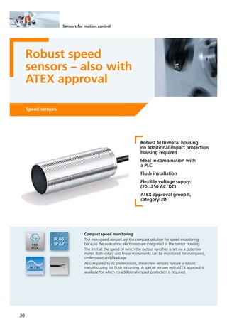
Especially in the field of conveying technology the
compact speed sensors can be used for various applica-
tions, for example for monitoring belt conveyors or
bucket elevators. Here they are typically used to monitor
underspeed, blockage or standstill.
Advantages
The speed sensors incorporate the complete speed
monitoring because the evaluation electronics and the
sensor are integrated in one housing. The switch point
is set using a multi-turn potentiometer. Hysteresis and
start-up delay are firmly set.
Operation
The integrated sensor is damped by passing cams or
other metallic targets. On the basis of the time interval
between damping the evaluation unit determines the
period duration or the frequency (actual rotational
speed value) and compares it to the set switch point
(preset value).
The output is switched during the start-up delay and
when the rotational speed exceeds the set switching
value.
An LED signals underspeed and switch-off of the
output.
Dimensions
80
75,5
M30x1,5
5,4
2,2
36
5
1
LEDs
1) potentiometer
WH
BK
L1
L+
L
N
Wiring
Target wheel E89010
Mounting clamp with end stop for
M30 types
E11049
Fixing clamp with reducing bush for
M30 types
E10077
Angle bracket for M30 types E10737
Lock nuts, nickel-plated brass E10030
Lock nuts, high-grade stainless steel
(316Ti/1.4571)
E10031
Mounting set, free-standing M12
clamp mounting, Ø 30.2 mm
E20873
Mounting set, aluminium profile
clamp mounting, Ø 30.2 mm
E20875
Clamp with damping cams E89013](https://image.slidesharecdn.com/ifm-product-news-2016-2017-en-170131091759/85/Newsbook-2016-2017-English-30-320.jpg)
![33
(11.2016)
Threshold display
DP2200
Dimensions
31
24
3
30
M12x1
M12x1
63
1
2
1) Push ring
2) LEDs
3) Display
Wiring diagram
43
2 1
3
1 2
4
5
M12: plug
Pin 1: L+ supply
Pin 2: OUT2 analogue output
Pin 3: L- supply
Pin 4: OUT1 switching output 1 or IO-Link
M12: Buchse
Pin 1: L+ sensor supply
Pin 2: 4...20 mA analogue input
Pin 3: L- sensor supply
Pin 4: not used
Pin 5: not used
Typical plant configuration
sensor parameter setting
LINERECORDER
sensor 4.0
IO-Link
Threshold
display
with
IO-Link
USB
adapter
PLC
4...20 mA
4...20 mA
industrial fieldbus
4...20 mA
IO-Link master
IP67
PLC
industrial fieldbus
IO-Link
sensors
without
IO-Link
···1 7 8
M
without
IO-Link
Operating voltage [V DC] 27 (typ. 24)
Inputs
1 x analogue,
4...20 mA
Ambient temperature [°C] -25...70
Protection IP 67
Output status indication LED yellow
Operation LED green
Wiring M12 connector
Outputs
1 x digital / IO-Link,
normaly open / closed
programmable
1 x analogue, 4...20 mA
Display
7-segment LED display
4-digit
red/green
programmable
Technical data
For further technical details please visit: www.ifm.com
Accessories
Type Description Order
no.
Mounting clip E89208
LINERECORDER SENSOR,
Software for parameter setting and
setting up IO-Link sensors
QA0001
USB IO-Link master for parameter setting
and analysis of units
Supported communication protocols:
IO-Link (4.8, 38.4 and 230 Kbits/s)
E30390](https://image.slidesharecdn.com/ifm-product-news-2016-2017-en-170131091759/85/Newsbook-2016-2017-English-32-320.jpg)
![35
(11.2016)
For further technical details please visit: www.ifm.com
Dimensions
Operating voltage
[V]
Inputs Inputs
programmable
Outputs
Transistor
Outputs
Relay
Order
no.
Multifunction display · touch display and clear text
24 DC 2 3 –– DX2031
24 DC 2 3 4V or mA DX2032
24 DC 2 3 4– DX2033
Operating voltage [V DC] 18...30
Current consumption [mA] approx. 150 (without load)
Sensor supply [V DC]
Output current
UB -1 V
max. 250 mA
Incremental inputs
Usage
Format
Frequency
PNP, NPN, Namur encoders
and sensors
HTL (10...30 V)
max. 250 kHz
Control inputs Format
Frequency
HTL, PNP (10...30 V)
max. 250 kHz
Analogue output
(only DX2032) Voltage output
Current output
Resolution
Accuracy
-10...10 V / 0...10 V
0...20 mA / 4...20 mA
16 bits
± 0.1 %
Control outputs
(DX2032 / DX2033) Format / level
Output current
3...30 V (depending on the
voltage on Com+), PNP
max. 250 mA (max. 150
mA at Com+ <10 V)
Display Type
Colour
Handling
LCD (backlight)
red, green, yellow
(selectable)
Touch screen (resistive)
Ambient temperature [°C] -20...60
Dimensions (W x H x D) [mm] 96 x 48 x 100
Common technical data
48
96,2 115,3
114](https://image.slidesharecdn.com/ifm-product-news-2016-2017-en-170131091759/85/Newsbook-2016-2017-English-34-320.jpg)

![37
(11.2016)
For further technical details please visit: www.ifm.com
Further technical data
O3M251
Housing material diecast aluminium
PAL resolution [pixels] 640 x 480
Type of sensor
1/4" 4:3 VGA CMOS
image sensor Color
Connection M12 connector
Protection rating,
protection class
IP 67 / IP 69K,
III
Operating voltage [V DC] 9...32
Current consumption sensor [mA] < 500
Current consumption [A]
system illumination unit
< 5
Ambient temperature [°C] -40...85
Interfaces
1x CAN,
1 x fast Ethernet,
1x PAL
Storage temperature -40...105
Supported CAN protocols
CANopen,
SAE J 1939
Standards and tests
(extract)
CE,
E1 (UN-ECE R10)
Resolution
[pixels]
Angle of aperture
horizontal x vertical
[°]
IlluminationAngle of aperture
2D
[°]
Order
no.
PMD 3D sensor · Type O3M · M12 connector
64 x 16 70 x 23
Ext. illumination
required (O3M950)
90 O3M251
Max.
sampling rate
[Hz]
25/33/50
Accessories
Type Description Order
no.
IR system illumination unit (850 nm)
for mobile 3D sensors,
angle of aperture 70 x 23
O3M950
CAN/RS232 USB interface CANfox EC2112
Adapter cable set for CANfox EC2114
Operating software for vision sensors E3D300
U-shaped bracket,
suitable for sensor or illumination
E3M100
Weather protective cover
(the article E3M100 or E3M102
is required for installation)
E3M101
U-shaped bracket,
suitable for sensor or illumination unit
E3M102
Connection technology
Type Description Order
no.
MCI cable, connection
sensor / system illumination unit, 0,25 m
E3M120
MCI cable, connection
sensor / system illumination unit, 1 m
E3M121
MCI cable, connection
sensor / system illumination unit, 2 m
E3M122
MCI cable, connection
sensor / system illumination unit, 3 m
E3M123
M12 video connection cable, connection
sensor / display PDM360, 5 m
E3M151
M12 video connection cable, connection
sensor / display PDM360, 11 m
E3M152
M12 video connection cable, connection
sensor / display PDM360, 16 m
E3M153
M12 video connection cable, connection
sensor / display PDM360, 21 m
E3M154
M12 socket, voltage supply system
illumination unit, 2 m,
PUR cable, 4 poles
E3M131
M12 socket, voltage supply system
illumination unit, 5 m,
PUR cable, 4 poles
E3M132
M12 socket, voltage supply system
illumination unit, 10 m,
PUR cable, 4 poles
E3M133
Ethernet, cross-over patch cable,
2 m, PVC cable, M12 / RJ45
E11898
Ethernet, cross-over patch cable,
10 m, PVC cable, M12 / RJ45
E12204
Ethernet, cross-over patch cable,
20 m, PVC cable, M12 / RJ45
E12205
CAN jumper,
screened, 2 m, PUR cable,
M12 plug / M12 socket
E11593
CAN jumper,
screened, 5 m, PUR cable,
M12 plug / M12 socket
E11594
CAN jumper,
screened, 10 m, PUR cable,
M12 plug / M12 socket
E11595
M12 video extension cable, 5 m E3M159
M12 video adapter cable / Cinch plug,
for connection of a video grabber, 1 m
E3M160](https://image.slidesharecdn.com/ifm-product-news-2016-2017-en-170131091759/85/Newsbook-2016-2017-English-36-320.jpg)

![39
(11.2016)
For further technical details please visit: www.ifm.com
Further technical data
O3M250
Housing material diecast aluminium
PAL resolution [pixels] 640 x 480
Type of sensor
1/4" 4:3 VGA CMOS
image sensor Color
Connection M12 connector
Protection rating,
protection class
IP 67 / IP 69K,
III
Operating voltage [V DC] 9...32
Current consumption sensor [mA] < 500
Current consumption [A]
system illumination unit
< 5
Ambient temperature [°C] -40...85
Interfaces
1 x fast Ethernet,
1x PAL
Storage temperature [°C] -40...105
Standards and tests
(extract)
CE,
E1 (UN-ECE R10)
Accessories
Connection technology
Type Description Order
no.
Resolution
[pixels]
Angle of aperture
horizontal x vertical
[°]
IlluminationAngle of aperture
2D
[°]
Order
no.
PMD 3D sensor · Type O3M · M12 connector
64 x 16 70 x 23
Ext. illumination
required (O3M950)
90 O3M250
Max.
sampling rate
[Hz]
25/33/50
Type Description Order
no.
IR system illumination unit (850 nm)
for mobile 3D sensors,
angle of aperture 70 x 23
O3M950
CAN/RS232 USB interface CANfox EC2112
Adapter cable set for CANfox EC2114
Operating software for vision sensors E3D300
U-shaped bracket,
suitable for sensor or illumination
E3M100
MCI cable, connection
sensor / system illumination unit, 0,25 m
E3M120
MCI cable, connection
sensor / system illumination unit, 1 m
E3M121
MCI cable, connection
sensor / system illumination unit, 2 m
E3M122
MCI cable, connection
sensor / system illumination unit, 3 m
E3M123
M12 video connection cable, connection
sensor / display PDM360, 5 m
E3M151
M12 video connection cable, connection
sensor / display PDM360, 11 m
E3M152
M12 video connection cable, connection
sensor / display PDM360, 16 m
E3M153
M12 video connection cable, connection
sensor / display PDM360, 21 m
E3M154
M12 socket, voltage supply system
illumination unit, 2 m,
PUR cable, 4 poles
E3M131
M12 socket, voltage supply system
illumination unit, 5 m,
PUR cable, 4 poles
E3M132
M12 socket, voltage supply system
illumination unit, 10 m,
PUR cable, 4 poles
E3M133
Ethernet, cross-over patch cable,
2 m, PVC cable, M12 / RJ45
E11898
Ethernet, cross-over patch cable,
10 m, PVC cable, M12 / RJ45
E12204
Ethernet, cross-over patch cable,
20 m, PVC cable, M12 / RJ45
E12205
CAN jumper,
screened, 2 m, PUR cable,
M12 plug / M12 socket
E11593
CAN jumper,
screened, 5 m, PUR cable,
M12 plug / M12 socket
E11594
CAN jumper,
screened, 10 m, PUR cable,
M12 plug / M12 socket
E11595
M12 video extension cable, 5 m E3M159
M12 video adapter cable / Cinch plug,
for connection of a video grabber, 1 m
E3M160
Weather protective cover
(the article E3M100 or E3M102
is required for installation)
E3M101
U-shaped bracket,
suitable for sensor or illumination unit
E3M102](https://image.slidesharecdn.com/ifm-product-news-2016-2017-en-170131091759/85/Newsbook-2016-2017-English-38-320.jpg)
![41
(04.2016)
For further technical details please visit: www.ifm.com
Description Order
no.
IR system illumination unit (850 nm) for mobile
3D sensors, angle of aperture 70 x 23
O3M950
IR system illumination unit (850 nm) for mobile
3D sensors, angle of aperture 95 x 32
O3M960
Further technical data
Smart sensors O3M151, O3M161
Accessories
Housing material diecast aluminium
Device connection M12 connector
Protection rating,
protection class
IP 67 / IP 69K,
III
Operating voltage [V DC] 9...32
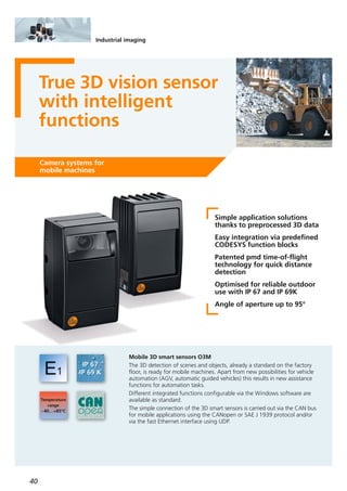
Functions and advantages
Powerful 3D time-of-flight measurement (ToF)
The principle of these 3D sensors is based on ifm’s
patented and award-winning pmd technology.
It was specifically designed for outdoor use and difficult
ambient light situations. Even interference such as sun-
light or materials with different reflective characteristics
do not influence the repeatability of the measured data.
Powerful electronics
The integrated 2 x 32-bit processor architecture ensures
a rapid and reliable calculation of the 3D data and
functions directly integrated in the system with up to
50 fps. The complete electronics of the mobile 3D smart
sensor is optimised and adapted to the demands and
requirements of mobile machines.
Besides shock and vibration resistance self-diagnostic
functions from the sensor to the IR system illumination
unit are of course also available.
Smart functions
The mobile 3D smart sensors integrate some functions
which enable a multitude of applications to be solved.
A highly developed algorithm from the automotive
industry is used ensuring, for example, reliable automatic
object recognition of up to 20 objects. This function
can, for example, be used as collision warning.
For simple distance tasks typical functions such as
minimum / maximum / average distance are available.
System parameter setting and monitoring
The parameter setting of the system and live monitoring
of the 3D data are carried out via the easy-to-use ifm
vision wizard for Windows. As an alternative, parameter
setting can also be carried out via function blocks using
the software CODESYS.
Communication interfaces
The preprocessed function data is output via the CAN
bus using CANopen or SAE J 1939. If needed, the
complete 3D information can be processed at the same
time via Ethernet UDP and an external process unit.
Current consumption sensor [mA] < 400
Current consumption [A]
system illumination unit
< 5
Ambient temperature [°C] -40...85
Interfaces
1x CAN,
1 x fast Ethernet
Supported CAN protocols CANopen, SAE J 1939
Standards and tests
(extract)
CE,
E1 (UN-ECE R10)
CAN/RS232 USB interface CANfox EC2112
Adapter cable set for CANfox EC2114
Operating software for vision sensors E3D300
U-shaped holder,
suitable for sensor or illumination unit
E3M100
Connection technology
MCI cable, connection
sensor / system illumination unit, 1 m
E3M121
MCI cable, connection
sensor / system illumination unit, 2 m
E3M122
Type Description Order
no.
M12 socket, voltage supply system
illumination unit, 2 m,
PUR cable, 4 poles
E3M131
M12 socket, voltage supply system
illumination unit, 10 m,
PUR cable, 4 poles
E3M133
Ethernet, cross-over patch cable,
2 m, PVC cable, M12 / RJ45
E11898
Ethernet, cross-over patch cable,
10 m, PVC cable, M12 / RJ45
E12204
Type of sensor Resolution
pixels
[pixel]
IlluminationAngle of aperture
horizontal x vertical
[°]
Order
no.
PMD 3D sensor · Type O3M · M12 connector
PMD 3D chip 64 x 16
ext. illumination
required (O3M950)
70 x 23 O3M151
Max.
sampling rate
[Hz]
25/33/50
PMD 3D chip 64 x 16
ext. illumination
required (O3M960)
95 x 32 O3M16125/33/50](https://image.slidesharecdn.com/ifm-product-news-2016-2017-en-170131091759/85/Newsbook-2016-2017-English-40-320.jpg)
![43
(04.2016)
For further technical details please visit: www.ifm.com
Further technical data
O3M150, O3M160
Housing material diecast aluminium
Device connection M12 connector
Protection rating,
protection class
IP 67 / IP 69K,
III
Operating voltage [V DC] 9...32
Functions and advantages
Powerful 3D time-of-flight measurement (ToF)
The principle of these 3D sensors is based on ifm’s
patented and award-winning pmd technology.
It was specifically designed for outdoor use and difficult
ambient light situations. Interference such as sunlight
or materials with different reflective characteristics
which occurs in the area of mobile machines does not
influence the repeatability of the measured data.
Powerful electronics
The integrated 2 x 32-bit processor architecture ensures
a rapid and reliable calculation of the distance image to
be output with up to 50 fps. The complete electronics
of the mobile 3D sensor is optimised and adapted to the
demands and requirements of mobile machines.
Besides shock and vibration resistance self-diagnostic
functions from the sensor to the IR system illumination
unit are of course also available.
High system uptime
The system has various features to ensure uninterrupted
operation. They include, among others, soiling indication
as well as different status information which can be
fetched from CAN.
System parameter setting and monitoring
The parameter setting of the system and live monitoring
of the 3D data are carried out via the easy-to-use ifm
vision wizard for Windows.
Communication interfaces
The mobile 3D sensors feature a fast Ethernet interface
(100 Mbit) as well as a CAN interface. The data output
of the complete 3D information is carried out via
Ethernet UDP and can be processed using a process
unit at the customer’s end. For this version the CAN in-
terface is only intended for parameter setting and
status output.
Current consumption sensor [mA] < 400
Current consumption [A]
system illumination unit
< 5
Ambient temperature [°C] -40...85
Interfaces
1x CAN,
1 x fast Ethernet
Connection technology
MCI cable, connection
sensor / system illumination unit, 1 m
E3M121
MCI cable, connection
sensor / system illumination unit, 2 m
E3M122
Type Description Order
no.
M12 socket, voltage supply system
illumination unit, 2 m,
PUR cable, 4 poles
E3M131
M12 socket, voltage supply system
illumination unit, 10 m,
PUR cable, 4 poles
E3M133
Ethernet, cross-over patch cable,
2 m, PVC cable, M12 / RJ45
E11898
Ethernet, cross-over patch cable,
10 m, PVC cable, M12 / RJ45
E12204
Type of sensor Resolution
pixels
[pixel]
IlluminationAngle of aperture
horizontal x vertical
[°]
Order
no.
PMD 3D sensor · Type O3M · M12 connector
PMD 3D chip 64 x 16
ext. illumination
required (O3M950)
70 x 23 O3M150
Max.
sampling rate
[Hz]
25/33/50
PMD 3D chip 64 x 16
ext. illumination
required (O3M960)
95 x 32 O3M16025/33/50
Description Order
no.
IR system illumination unit (850 nm) for mobile
3D sensors, angle of aperture 70 x 23
O3M950
IR system illumination unit (850 nm) for mobile
3D sensors, angle of aperture 95 x 32
O3M960
Accessories
Supported CAN protocols CANopen, SAE J 1939
Standards and tests
(extract)
CE,
E1 (UN-ECE R10)
CAN/RS232 USB interface CANfox EC2112
Adapter cable set for CANfox EC2114
Operating software for vision sensors E3D300
U-shaped holder,
suitable for sensor or illumination unit
E3M100](https://image.slidesharecdn.com/ifm-product-news-2016-2017-en-170131091759/85/Newsbook-2016-2017-English-42-320.jpg)

![45
(11.2016)
For further technical details please visit: www.ifm.com
Connection technology
Type Description Order
no.
Connection cable, M16, 3,85 m, 8 poles,
for the voltage supply of the
E2M250 multi-view box, open cable end
E2M251
Socket, M16, wirable
8 poles, for the voltage supply of the
E2M250 multi-view box
E2M252
Adapter cable, 0.6 m black, PUR cable,
M12 connector / M16 socket, to connect
the MultiViewBox to the PDM NG
E2M200
Jumper,
5 m black, PUR cable,
M16 plug / M16 socket
E2M203
Jumper,
11 m black, PUR cable,
M16 plug / M16 socket
E2M204
Jumper,
16 m black, PUR cable,
M16 plug / M16 socket
E2M205
Jumper,
21 m black, PUR cable,
M16 plug / M16 socket
E2M206
Current consumption [mA] < 1200
Video signal
PAL (25 fps,
interlacing)
720H x 576V
(active 680 x 480)
Ambient temperature [°C] -40...85
Protection IP 67 (ISO 20653)
Approval UN-ECE R10
Housing materials
stainless steel
SS316 (1.4401)
Connection M16 connector
MultiViewBox
E2M250
Technical data
Operating voltage [V DC] 10...32 DC
Products
Order
no.
Video splitter,
visualisation of up to 4 camera images
(PAL) on one process and dialogue mo-
dule
E2M250
Type Description
Angle of aperture 78°,
lens heating
O2M200
Angle of aperture 78°, lens heating,
integrated mirror function
O2M201
Angle of aperture 115°,
lens heating
O2M202
Angle of aperture 115°, lens heating,
integrated mirror function
O2M203
MultiViewBox
Analogue camera,
0.5 m connection cable with M16 connector
Dimensions
180
160
113,5
100
73
85
1,5
40
1 2 3 4 5 6
1) INPUT
2) OUTPUT
3) C4
4) C3
5) C2
6) C1](https://image.slidesharecdn.com/ifm-product-news-2016-2017-en-170131091759/85/Newsbook-2016-2017-English-44-320.jpg)

![47
(11.2016)
For further technical details please visit: www.ifm.com
Mounting set for O3D E3D301
Further technical data
Accessories
Operating voltage [V DC] 20.4...28.8
Current consumption [mA]
< 2400 peak current
pulsed;
typ. mean value
420
Current rating [mA]
(per switching output)
100
Real chip resolution
25,000 /
100,000
Resulting resolution
176 x 132
pixels
Function display LED
2 x yellow,
2 x green
Illumination
850 nm,
infrared
Ambient light [lux]
max. 10,000
(indoor)
Trigger
external;
24 V PNP / NPN
according to
IEC 61131-2 type 3
Switching inputs
2
(configurable),
24 V PNP/NPN
according to
IEC 61131-2 type 3
Switching outputs
digital
3
(configurable),
24 V PNP/NPN,
according to
IEC 61131-2
Switching outputs
analogue
1
(can be configured as
current output 4...20 mA
or voltage
output 0...10 V)
Ambient temperature [°C] -10...50
Ethernet, cross-over patch cable,
2 m, PVC cable, M12 / RJ45
E11898
Ethernet, jumper cables,
2 m, PVC cable, M12 / M12
E21138
Type of sensor Material
front pane /
LED window
Angle of
aperture
[°]
Protection rating,
protection class
Order
no.
PMD 3D sensors · Type O3D · M12 connector
PMD 3D ToF chip
Gorilla glass /
polyamide
Material
housing
Aluminium 40 x 30
IP 65 / IP 67,
III
O3D300
Max. field
of view size
[m]
2.61 x 3.47
PMD 3D ToF chip
Gorilla glass /
polyamide
Aluminium 60 x 45
IP 65 / IP 67,
III
O3D3023.75 x 5.00
PMD 3D ToF chip
Polycarbonate /
polyamide
Stainless steel 40 x 30
IP 65, IP 67, IP 69K /
III
O3D3102.61 x 3.47
PMD 3D ToF chip
Polycarbonate /
polyamide
Stainless steel 60 x 45
IP 65, IP 67, IP 69K /
III
O3D3123.75 x 5.00
Socket, M12,
2 m black, PUR cable, 8 poles
E11950
Type Description Order
no.
Cooling element E3D302
Double cooling element E3D304
Heat conductor E3D303
Short-circuit protection, pulsed •
Overload protection •
Parameter setting interface
Ethernet
10 Base-T / 100 Base-TX
Possible parameter settings
via PC /
notebook
Dimensions (H, W, D) [mm] 72 x 65 x 85
Technical data
Level measurement and point level detection
Typ. level [m] 0.3...6
Operating distance max. [m] 10
Sampling rate [Hz] 5
Mounting accessories
Connection technology](https://image.slidesharecdn.com/ifm-product-news-2016-2017-en-170131091759/85/Newsbook-2016-2017-English-46-320.jpg)
![49
(04.2016)
For further technical details please visit: www.ifm.com
Accessories
Type Description Order
no.
Operating voltage PT [V DC]
PU [V DC]
8...32
16...32
Common technical data
Medium temperature [°C] -40...125
Materials wetted parts
1.4542 (17-4 PH / 630),
characteristics similar to
stainless steel
(e.g. 304/1.4301)
but higher strength
Protection IP 67 / IP 69K
Step response time [ms] 2
Restrictor •
EMC
Compliant with UN-ECE10
Rev. 4
ISO 11452: 100 V/m
EN61326
Reverse polarity protection •
Adapters; G 1/4 - G 1/2,
high-grade stainless steel (316Ti/1.4571)
E30135
Accuracy / deviation
(in % of the span)
Linearity error
Linearity
Hysteresis
Repeatability
Long-term stability
Temperature coefficients (TEMPCO)
in the temperature range 0 ... 80 °C
(in % of the span per 10 K)
TEMPCO of zero
TEMPCO of the span
Temperature coefficients (TEMPCO)
in the temperature ranges
-40...0 °C and 80...125 °C
(in % of the span per 10 K)
TEMPCO of zero
TEMPCO of the span
< ± 0.8
< ± 0.25 BFSL / < ± 0.5 LS
< ± 0.2
< ± 0.05
< ± 0.1
< ± 0.1
< ± 0.1
< ± 0.2
< ± 0.2
Wiring diagram
Dimensions
12
65,9
51,6
M12x1
18,9
G
1 4
/
19
1
Example: type PT55
1) HNBR seal / DIN 3869
PU5704
PU5703
PU5702
PU5701
PU5700
PU5760
PU5604
PU5603
PU5602
PU5601
PU5600
PU5660
Measuring range
relative pressure
[bar]
Poverload
max.
[bar]
Pburst
min.
[bar]
Output function 4…20 mA,
0...10 25 300
0...25 65 600
0...100 250 1000 PT5702
0...250 625 1200 PT5701
0...400 1000 1700 PT5700
0...600 1500 2400 PT5760
Output function 0...10 V
0...10 300
0...25 600
0...100 1000
PT5602
0...250 1200
PT5601
0...400 1700
PT5600
0...600 2400
PT5660
PT5502
PT5501
PT5500
PT5560
25
65
250
625
1000
1500
Order
no.
PT5504
M12 connector
PT5503
Order
no.
PT5604
AMP connector
PT5603
Order
no.
PT5704
DEUTSCH connector
M12 connector AMP connector DEUTSCH connector
PT5703
L+
BN1
WH2
OUT
Type PT55
1
2
3
OUT
L +
L -
Type PU56
A
B
OUT
+L
A
C
B
OUT
L -
L +L +
Type PU57Type PT57
1
3
L +
OUT
Type PT56
–
–
–
–
–
–](https://image.slidesharecdn.com/ifm-product-news-2016-2017-en-170131091759/85/Newsbook-2016-2017-English-48-320.jpg)
![51
(04.2016)
For further technical details please visit: www.ifm.com
Splitter box *
with vent and terminal block
E30401
Additional weight, approx. 500 g E30402
Filter element * E30400
Cable fixing clamps * E30399
Submersible pressure transmitters with PUR cable for standard applications
0.6
0.6
0.6
4
4
4
1000 N
1000 N
1000 N
Measuring range
Relative pressure
[bar]
Approvals
CE / EX / GL
Overload pressure
[bar]
Pull force cable
1
1
5
5
1000 N
1000 N
Cable length
[m]
PS3407
PS3427
PS3607
Order
no.
PS3417
PS3617
0.25 2 1000 N
10
15
30
15
30
5
• / – / –
• / – / –
• / – / –
• / – / –
• / – / –
• / – / – PS3208
Operating voltage [V DC] 18...30
Analogue output [mA] 4...20
Accuracy / deviation
(in % of the span)
Accuracy (BFSL)
Accuracy incl. non-linearity
Non-linearity (BFSL)
Long-term stability per year
≤ 0.25 (PS3: 0.5)
≤ 0.5 (PS3: 1)
≤ 0.2
≤ 0.2
Design PS3
Ambient temperature / [°C]
Medium temperature
-10...50
Design PS4
Ambient temperature / [°C]
Medium temperature
-10...85
Design PS3
ATEX approval
Ambient temperature / [°C]
Medium temperature
1G, 1/2G, 2G:
T6 -10...60, T5: -10...80,
T4: -10...85
1D, 1/2D, 2D:
-10...40 (750 mW) / -
10...70 (650 mW) / -
10...85 (550 mW)
Housing material
High-grade stainless steel
(316Ti / 1.4571)
Further technical data
Accessories
Type Description Order
no.
* use only outside the hazardous area
Submersible pressure transmitters with FEP cable for high resistance to media
0.6
1
3
5
500 N
500 N
PS4407
PS4417
0.25 2 500 N
10
15
5
• / – / –
• / – / –
• / – / – PS4208
Submersible pressure transmitters with FEP cable for hazardous areas
0.6
1
4
5
500 N
500 N
PS307A
PS317A
0.25 2 500 N
10
15
5
• / • / •
• / • / •
• / • / • PS308A
Temperature coefficients (TEMPCO)
(in % of the span per 10 K)
Greatest TEMPCO of zero
Greatest TEMPCO of the span
≤ 0.2
≤ 0.2
100
27
Example PS3208
Dimensions
0.6
1
3
5
500 N
500 N
PS4506
PS4607
0.25 2 500 N
20
30
10
• / – / –
• / – / –
• / – / – PS4408](https://image.slidesharecdn.com/ifm-product-news-2016-2017-en-170131091759/85/Newsbook-2016-2017-English-50-320.jpg)

![53
(04.2016)
For further technical details please visit: www.ifm.com
Accessories
Type Description Order
no.
Operating voltage [V DC] 8...30
Common technical data
Medium temperature [°C] 0...80
Materials (wetted parts)
NBR,
high-grade stainless steel
(316L/1.4404)
Protection IP 67
Step response time [ms] 4
Reverse polarity protection •
Adapter; G 1/4 - G 1/2,
high-grade stainless steel (316Ti/1.4571)
E30135
Measuring range
[bar]
Poverload
max.
[bar]
Pburst
min.
[bar]
Order
no.
Output function 4...20 mA
0...1 5 PT0507
0...1.6 10 PT0517
0...4 25 PT0505
0...10 50 PT0504
Accuracy / deviation
(in % of the span)
Linearity error
Linearity
Repeatability
Temperature error in the
temperature range 0...80 °C
< ± 1.0
< ± 0.5 BFSL / < ± 1.0 LS
< ± 0.1
< ± 2.5 %
Connection technology
Type Description Order
no.
M12 socket,
2 m black, PUR cable
EVC001
M12 socket,
5 m black, PUR cable
EVC002
M12 socket,
2 m black, PUR cable
EVC004
M12 socket,
5 m black, PUR cable
EVC005
L+
BN1
WH2
OUT
Wiring diagram
Dimensions
14
47
58,8
G¼
29
M12x1
27
1
1) Sealing
2
3.2
8
20](https://image.slidesharecdn.com/ifm-product-news-2016-2017-en-170131091759/85/Newsbook-2016-2017-English-52-320.jpg)

![55
(04.2016)
For further technical details please visit: www.ifm.com
Resolution
pixels
Display type Display
illumination
Order
no.
1.44" colour display
128 x 128 TFT LED E30391
Wiring
Dimensions
Technical data
IO-Link display
E30391
Operating voltage [V DC] 18...30
Current consumption [mA] < 47
Protection rating /
protection class
IP 65, IP 67 /
III
Reverse polarity protection •
Ambient temperature [°C] 0...60
EMC
EN 61000-6-2
EN 61000-6-4
Shock resistance [g] 20 (11 ms)
Vibration resistance [g] 20 (10...50 Hz)
Housing materials
Stainless steel
(303/1.4305);
PC; PBT-GF 30;
PPS; PA 6.6; FKM
Connection M12 connector
Communication interface
IO-Link device
Type of transmission
IO-Link revision
SDCI standard
COM2 (38.4 kbaud)
1.1
IEC 61131-9
Connection technology
Type Description Order
no.
M12 jumper
1 m black, PUR cable
EVC042
M12 jumper
2 m black, PUR cable
EVC043
M12 jumper,
3 m black, PUR cable
EVC102
M12 jumper,
5 m black, PUR cable
EVC044
M12 jumper,
10 m black, PUR cable
EVC493
BN1
BK4
BU3
L+
L
OUT
45
34
86
101
39,5
11
M12x1
Accessories
Type Description Order
no.
DIN rail clip,
PA; 1.4567 (V2A)
E30429](https://image.slidesharecdn.com/ifm-product-news-2016-2017-en-170131091759/85/Newsbook-2016-2017-English-54-320.jpg)

![57
(04.2016)
For further technical details please visit: www.ifm.com
Common technical data
Operating voltage [V] 18...30 DC
Current consumption [mA] < 100
Current rating [mA] 250
Housing materials
High grade stainless steel
(1.4404/316L);
PBT-GF 20;
PBT-GF 30
Connection M12 connector
Accuracy temperature measurement ± 0.3 K
Type
SA
Protection rating, protection class IP 65 / IP 67, III
BN
WH
BK
BU
4
1
3
2
OUT2
L+
L
OUT1
Wiring
Measuring range
liquid / gaseous
[cm/s]
Medium
temperature
[°C]
Response
time
[s]
Order
no.
M12 connector · electrical design DC PNP
5...300 / 200...10000 -20...90 0.5 SA5000
Probe length
[mm]
45
5...300 / 200...10000 -20...100 0.5 SA4100100
5...300 / 200...10000 -20...100 0.5 SA4300200
Pressure
resistance
[bar]
100
50
50
Type
M18
Progressive ring
Progressive ring
Connection technology
Type Description Order
no.
M12 socket,
2 m black, PUR cable
EVC001
M12 socket,
5 m black, PUR cable
EVC002
M12 socket,
2 m black, PUR cable
EVC004
M12 socket,
5 m black, PUR cable
EVC005
M12 socket,
2 m orange, PVC cable
EVT064
M12 socket,
5 m orange, PVC cable
EVT001
Accuracy flow measurement
± (5 % MW
+ 2 % VMR)
at reference
conditions
Accessories
Type Description Order
no.
Progressive ring fitting G 1/2,
flat seal
E40258
Progressive ring fitting G 1/4,
flat seal
E40259
Progressive ring fitting G 3/4,
flat seal
E40260
USB IO-Link master for parameter setting
and analysis of units
Supported communication protocols:
IO-Link (4.8, 38.4 and 230 Kbits/s)
E30390
Progressive ring fitting 1/2 NPT E40261
Progressive ring fitting 1/4 NPT E40262
Progressive ring fitting R 1/2 E40263
Progressive ring fitting R 1/4 E40264
Progressive ring fitting
for SL mounting adapter
E40269
Protective cover for fluid sensors with
M12 connector,
polypropylene homopolymer
E30420
Welding adapter for cutting ring E40265
Flow adapter E40434
Progressive ring fitting G 1/2,
metal to metal seal
E40267
Progressive ring fitting G 3/4
metal to metal seal
E40268](https://image.slidesharecdn.com/ifm-product-news-2016-2017-en-170131091759/85/Newsbook-2016-2017-English-56-320.jpg)
![59
(11.2016)
For further technical details please visit: www.ifm.com
IO-Link interface for parameter setting
and analysis of units with
DTM specification, current consumption
from USB port: max. 500 mA
E30396
Memory plug, parameter memory
for IO-Link sensors
E30398
LINERECORDER SENSOR,
software for parameter setting and
setting up IO-Link sensors
QA0001
IO-Link accessories
Type Description Order
no.
Connection technology
Type Description Order
no.
Socket, M12,
2 m black, PUR cable
EVC001
Socket, M12,
5 m black, PUR cable
EVC002
Socket, M12,
2 m black, PUR cable
EVC004
Socket, M12,
5 m black, PUR cable
EVC005
Operating voltage [V DC] 18...32
Protection rating
protection class
IP 69K,
lll
Materials wetted parts
high-grade stainless steel
(316L/1.4404)
Further technical data
Reverse polarity / overload protection • / •
Dynamic response T05 / T09 1 s / 3 s
Accuracy [K] ± 0.3
Measuring range [°C] -50...150
Ambient temperature [°C] -25...80
IO-Link revision 1.1
Dimensions
Wiring diagram
Example TV7105
Example TV7603
Installation
length
[mm]
Order
no.
Pressure rating
[bar]
Output function 2 x NO / NC programmable,
measuring range -50...150 °C
25 400
30 300
25 400
30
Process
connection
G 1/4
G 1/2
1/4" NPT
1/2" NPT 300
TV7105
TV7405
TV7603
TV7303
Example TV7105
6
M12x1
18,7
15,9 48
19
13
G ¼
25
BN
WH
BK
BU
4
1
3
2
OUT2
L+
L
OUT1
6
M12x1
18,7
15,9 48
71
19 ¼" NPT
25](https://image.slidesharecdn.com/ifm-product-news-2016-2017-en-170131091759/85/Newsbook-2016-2017-English-58-320.jpg)
![61
(11.2016)
For further technical details please visit: www.ifm.com
Dimensions
M12x1
27
6
G ¼
59
50
12
27LED
Example TK6110
Dynamic response T05 / T09 [s] 1 / 3
Accuracy
Setting accuracy [K]
Temperature influence (per 10 K)
Repeatability [K]
± 3
0.1
± 0.1
Ambient temperature [°C] -40...70
Shock resistance 50 g
Vibration resistance 20 g
Housing materials
high-grade stainless steel
(316L/1.4404),
PC (Makrolon),
PBT (Pocan), FPM (Viton)
Materials wetted parts
high-grade stainless steel
(316L/1.4404),
FPM (Viton)
Connection M12 connector
Protection rating, protection class IP 67 / III
Operating voltage [V DC] 9.6...32
Current rating [mA] 500
Further technical data
Measuring range
[°C / °F]
Order
no.
M12 connector, gold-plated contacts · output function normally open / normally closed complementary
TK6110-25…140 / -13...284
Process connection
G 1/4
Installation length
[mm]
50
Switching hysteresis
[K]
adjustable
Pressure rating
[bar]
400
TK6310-25…140 / -13...284 1/4 NPT 50 adjustable 400
M12 connector, gold-plated contacts · output function 2 x normally open
TK7110-25…140 / -13...284 G 1/4 50 5 (fixed) 400
M12 connector, gold-plated contacts · output function 1 x normally open / 1 x normally closed
TK7460-25…140 / -13...284 G 1/2 250 5 (fixed) 300
Adapter,
G 1/4 – G 1/2
high-grade stainless steel (316Ti/1.4571)
E30135
Protective cover with lead seal option
for TK type temperature sensors,
PP transparent
E30094
Accessories
Type Description Order
no.
Flange adapter G1/4,
stainless steel (303/1.4305)
E30063
Thermowells
G 1/4 E377002750
Screw-in thermowell, process connection G 1/4
G 1/2 E37640224250
Screw-in thermowell, process connection G 1/2
Device connection Installation length [mm]
Sensor Thermowell
Order
no.
Connection technology
Type Description Order
no.
Socket, M12,
2 m black, PUR cable
EVC001
Socket, M12,
5 m black, PUR cable
EVC002
Socket, M12,
2 m black, PUR cable
EVC004
Socket, M12,
5 m black, PUR cable
EVC005
Socket, M12,
2 m black, PUR cable, LED
EVC007
Socket, M12,
5 m black, PUR cable, LED
EVC008](https://image.slidesharecdn.com/ifm-product-news-2016-2017-en-170131091759/85/Newsbook-2016-2017-English-60-320.jpg)
![63
(04.2016)
For further technical details please visit: www.ifm.com
Adapter, M18 x 1.5 - G 1/2
High-grade stainless steel (316L/1.4404)
E40096
Protective cover for fluid sensors with
M12 connector,
polypropylene homopolymer
E30420
Accessories
Type Description Order
no.
Accuracy [K] ± 0.3 + (± 0.1 % MS)
Electrical design PNP / NPN
Protection IP 67
Communication interface IO-Link
Resolution display [K] 0.1
Operating voltage [V] 18...32 DC
Current rating [mA] 250
Further technical data
IO-Link interface for parameter setting
and analysis of units with
DTM specification, current consumption
from USB port: max. 500 mA
E30396
Memory plug, parameter memory
for IO-Link sensors
E30398
LINERECORDER SENSOR,
software for parameter setting and
setting up IO-Link sensors
QA0001
IO-Link accessories
Type Description Order
no.
USB IO-Link master for parameter setting
and analysis of units
Supported communication protocols:
IO-Link (4.8, 38.4 and 230 Kbits/s)
E30390
1) LEDs (display unit / switching status), 2) 4-digit alphanumeric
display / alternating indication of red and green, 3) Programming
buttons, 4) Upper part of the housing can be rotated by 345°
Installation length
[mm]
Pressure resistance
[bar]
300 45
Measuring range
[°C]
Factory setting
[°C]
Order
no.
Output function 1 x NO / NC programmable · 1 x analogue output 4…20 mA or 0…10 V programmable
-50...150 -40...150
Process connection
M18 x 1.5 I TN2511
300 45
Output function 2 x NO / NC programmable
-50...150 -40...150M18 x 1.5 I TN7511
300 30 -50...150G 1/2 TN2405
300 50 -50...150G 1/2 TN2415
160 100 -50...150G 1/2 TN2435
160 150 -50...150G 1/2 TN2445
300 30 -50...1501/2" NPT TN2303
300 50 -50...1501/2" NPT TN2313
160 100 -50...1501/2" NPT TN2333
160 150 -50...1501/2" NPT TN2343
400 25 -50...150G 1/4 TN2105
400 50 -50...150G 1/4 TN2115
400 25 -50...1501/4" NPT TN2603
400 50 -50...150
-50...150
-50...150
-50...150
-50...150
-50...150
-50...150
-50...150
-50...150
-50...150
-50...150
-50...150
-50...1501/4" NPT TN2613
Output function 2 x NO / NC programmable or
1 x NO / NC + 1 x analogue (4...20 mA / 0...10 V; scalable)
Response dynamics T05 / T09 [s] 1 / 3
Thermowell for temperature sensors,
Ø 6 mm,
high-grade stainless steel
(316L/1.4404)
E37610
Dimensions
48
M12x1
22
EL11
41
34
80
121
4
3
2
1
G ¼
6
Example 2105](https://image.slidesharecdn.com/ifm-product-news-2016-2017-en-170131091759/85/Newsbook-2016-2017-English-62-320.jpg)
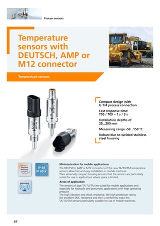
![65
(04.2016)
For further technical details please visit: www.ifm.com
Installation length
[mm]
Order no.
Factory setting
Connector
G 1/4 process connection
Analogue output 4...20 mA
25 M12
50 M12
200 M12
25 DEUTSCH
G 1/4 process connection
Analogue output 0.5...4.5 V
25 M12
25 DEUTSCH
25 AMP
Operating voltage [V DC]
Type TA
10...30
Operating voltage [V DC]
Type TU
8...32
Protection rating IP 68, IP 69K / lll
Materials in contact
with the medium
High-grade stainless steel
(316L/1.4404)
Further technical data
Reverse polarity / overload protection • / •
Response dynamics T05 / T09 1 s / 3 s
Ambient temperature [°C] -40...100
EMC
DIN EN 61000-6-2
DIN EN 61000-6-3
Dimensions
TA3105
TA3115
TA3155
TA4105
50 DEUTSCH TA4115
25 AMP TA5105
50 AMP TA5115
TU3105
TU4105
TU5105
-50...150 °C
-50...150 °C
G 1/4 process connection
Pt1000, class A
25 M12
25 DEUTSCH
TM5101
TM6101
-40...150 °C
1/4" NPT process connection
Analogue output 4...20 mA
50 M12
50 M12
TA3313
TA3317
0...300 °F /
0...100 °C
Wiring
M12x1
18,8
6
55,3 13
EL
19 G ¼
TA31
21,8
6
25,4
EL
1359,6
19 G ¼
TA41
25,8
6
EL
1359,8
19 G ¼
21,8
TA51
L+
BN1
WH2
OUT
BN1
WH2
BU3
L+
L
OUT
TU31TA31
A
C
B
OUT
L -
L +L +
TU41
1
3
L +
OUT
1
2
3
OUT
L +
L -
TU51TA51
A
B
OUT
+L
TA41](https://image.slidesharecdn.com/ifm-product-news-2016-2017-en-170131091759/85/Newsbook-2016-2017-English-64-320.jpg)

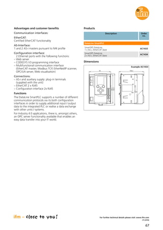
![69
(04.2016)
For further technical details please visit: www.ifm.com
Products
Protection IP 20,
Combicon connectors
AC3225
Total current consumption [mA]
via AS-i
2 x 60
Ambient temperature [°C] -25...70
Housing material PA 6.6
SmartLine AS-i repeater
AC3225
Technical data
SmartLine AS-i repeater
Order
no.
Description
Dimensions
10825,4
93
125,7
1
LED
2
3
35,5
1) plug with cage clamp connection
2) panel for labelling
3) Din rail adapter
Operating voltage [V DC] 26.5...31.6
AS-i power supply 115/230 V AC,
output current (AS-i) 2.8 A
AC1256
AS-i power supply 115/230 V AC,
output current (AS-i) 8 A
AC1258
Accessories
Order
no.
Type Description](https://image.slidesharecdn.com/ifm-product-news-2016-2017-en-170131091759/85/Newsbook-2016-2017-English-68-320.jpg)

![73
(11.2016)
For further technical details please visit: www.ifm.com
Dimensions
LED
M12
M12
26
31,6
38,4
152
136
59,3
5,3
Advantages and customer benefits
• Configuration of sensors with
LR DEVICE
The intuitive software finds all IO-Link masters in the
Ethernet network and creates an overview of the
whole plant. Besides, all sensors connected are in-
dicated with the respective parameters. This means
that parameter setting of all sensors in the system is
possible from one central point.
• Easy sensor connection
The sensors and actuators are connected via standard
M12 connection cables without screening. Up to
4 IO-Link sensors can be connected and be supplied
with up to 3.6 A. With the EVC693 accessories,
additional auxiliary supply for the connection of
IO-Link actuators can be supplied.
The cable can be up to 20 m long.
• Reliable digital data
The sensor data is transferred digitally. Unlike analogue
signals, contact resistance and EMC interference
cannot corrupt the signals.
• Direct connection to the IT
The integrated LR AGENT EMBEDDED is capable
of transmitting the process values directly to ERP
systems, without detour via the PLC.
This second communication path is available in parallel
to PROFINET via the bus wiring.
Products
Protection rating IP 65 / IP 67,
I/O modules for field applications
AL1100
Total current consumption [A] ≤ 3.9
IO-Link version 1.1
Number of IO-Link ports 4
Number of binary inputs
4 + 4
(IO-Link in SIO mode)
Number of binary inputs
4
(IO-Link in SIO mode)
Parameter memory •
Current for all ports [A]
(device supply)
≤ 3.6
Ambient temperature [°C] -25...60
Housing materials
Polyamide;
socket:
nickel-plated brass
4-port IO-Link master
AL1100
Technical data
IO-Link master with PROFINET interface
Order
no.
Description
Operating voltage [V DC] 20...30
Connection technology
Description Order
no.
M12 Y-splitter,
1 m black, PUR cable
EVC693
M12 Y-splitter,
2 m black, PUR cable
EVC694
M12 Y-splitter,
5 m black, PUR cable
EVC695
M12 Y-splitter,
10 m black, PUR cable
EVC696](https://image.slidesharecdn.com/ifm-product-news-2016-2017-en-170131091759/85/Newsbook-2016-2017-English-72-320.jpg)


![81
(04.2016)
For further technical details please visit: www.ifm.com
Description Order
no.
E80370
ID tag/30X2.8/03 – 13.56 MHz,
16 Kbits – FRAM
E80371ID tag/30X2.5/06 – 13.56 MHz, 896 bits
E80377
ID tag/R20X2.5/06 – 13.56 MHz,
896 bits
The products
E80380ID tag/30X2.8/03 – 13.56 MHz, 64 Kbits
E80381
ID tag/4.35X3.6/03 – 13.56 MHz,
896 bits, 10 pcs
E80382
ID tag/label 65X30/03 – 13.56 MHz,
896 bits, 500 pcs
E80379
ID tag/label 80X50/03 – 13.56 MHz,
896 bits, 500 pcs
Further technical data
Operating voltage [V DC] 9...32
Current consumption sensor [mA]
< 50 at 24 V,
< 85 at 12 V
Ambient temperature [°C] -40...85
Protection rating,
protection class
IP 67 / IP 69K,
III
Housing material stainless steel
Interfaces 1 x CAN
Supported CAN protocols CANopen, SAE J1939
Standards and tests
(extract)
CE,
radio approval
Connection M12 connector
Jumper, M12,
5 m, black, PUR cable, LED
EVC039
Jumper, M12,
5 m, black, PUR cable
EVC069
Socket, M12,
2 m black, PUR cable
EVM036
Socket, M12,
10 m black, PUR cable
EVM038
Socket, M12,
5 m black, PUR cable
EVC492
RFID transponders
Accessories
BasicDisplay XL, 4,3",
CAN Interface
CR0452
Display
Connection technology
Type Description Order
no.
Type Description Order
no.
Process and dialogue unit PDM360 NG,
7" colour display
CR1081
DTM424M18 flush, 13.56 MHz
DTM425M18 non-flush, 13.56 MHz
DTM434M30 flush, 13.56 MHz
DTM435M30 non-flush, 13.56 MHz
RFID evaluation unit / RFID antenna
CANopen interface
DTM426
DTM427
DTM436
DTM437
RFID evaluation unit / RFID antenna
SAE J1939 interface
M18 flush, 13.56 MHz
M18 non-flush, 13.56 MHz
M30 flush, 13.56 MHz
M30 non-flush, 13.56 MHz
Application
Mobile machines are becoming ever more complex
and complicated to use. Individual components assume
more and more tasks.
With ifm's RFID system handling can be simplified
and errors can be avoided: individual components or
attachments are identified by means of an RFID tag and
the corresponding set-up is set automatically in the
controller.
Set-up times are minimised. Automatic identification
simplifies the creation of user-specific system set-ups.
Wrongly set process parameters are a thing of the past.
Higher productivity
Information on maintenance intervals and operating
times can automatically be generated and stored since
the controller detects when and how long a specific
machine set-up runs. This increases productivity.
Perfectly suited for use in industrial applications
The RFID system is also suitable for industrial applications
in which CANopen controllers are used.
In this environment the DTM4xx RFID identification
system is ideal thanks to its excellent price / performance
ratio.](https://image.slidesharecdn.com/ifm-product-news-2016-2017-en-170131091759/85/Newsbook-2016-2017-English-80-320.jpg)
![83
(11.2016)
For further technical details please visit: www.ifm.com
Functions and advantages
The compact real-time clock is an ideal add-on both
for control systems in small and compact machines and
complex process controllers of big machines.
• Mechanical design
The compact housing of the electronics is equipped
with an ISO 7588 blade arrangement providing all
necessary connections.
These are easy to handle and available all over the
world. The CANrtc can also be used in areas that
are exposed to splashing water due to an increased
protection rating if installed in connection with the
BasicRelay CR0421 and the corresponding module
cover.
• Powerful electronics
The electronics are optimally adapted to the applica-
tion. The integrated buffer battery reliably bridges
any supply voltage interruptions. At a freely adjustable
point of time, the alarm output activates a connected
consumer or the system electronics.
• Programmable to IEC 61131-3
The CODESYS software enables a clear and easy
creation of the application software for the user. For
the CANrtc real-time clock, a library with the necessary
functions for parameter setting and communication
is available.
The parameters can be set and read via the user
program. The RTC data is also available to other bus
participants via the open CANinterface.
Description Order
no.
CAN real-time clock – CANrtc CR3020
Products
BasicRelay locations for 6 automotive relays ad
10 automotive fuses (6.3 mm), 2 supply rails and
6 power distributors, freely wirable
CR0421
Contact set for BasicRelay CR0421, wirable, utilising all
connections to a BasicController relay
EC0457
Cover for BasicController CR04xx and
BasicRelay CR042x, incl. cable seal
EC0401
CAN programming interface CANfox EC2112
Adapter set CAN/RS232 for CANfox EC2113
CODESYS programming software, German CP9006
CODESYS programming software, English CP9008
Indication 1 x status LED (green)
Programming
CODESYS (IEC 61131-3)
or
CAN Layer 2 commands
RTC format
Day / month / year /
hour / minute /
second / day of the week
RTC accuracy
± 2 s/day
(at 25°C)
RTC battery life
≤ 15 years
(cannot be replaced)
Standards and tests
For further information,
please refer to the data
sheet: www.ifm.com
Technical data
CAN real-time clock – CANrtc
Housing Plastic
Device connection
6.3 mm flat-pin connector
with a blade arrangement
to ISO 7588
(can be used for example
with BasicRelay CR0421 or
automotive relay holder)
Protection rating,
in connection with BasicRelay CR0421
and cover EC0401
IP 20
IP 54
Operating voltage [V DC] 8...32
Current consumption [mA] 6 (at 24 V DC)
Temperature range
Operation [°C]
Storage [°C]
-40...85
-40...85
CAN interface
125 kbit/s / 250 kbit/s /
500 kbit/s
(Default: 250 kBit/s),
CAN Layer 2
Output
Switching voltage / switching current
Semiconductor output,
Positive switching
(high side) Short-circuit
and Overload protection
UB - max. 1.5 V DC / ≤ 2 A](https://image.slidesharecdn.com/ifm-product-news-2016-2017-en-170131091759/85/Newsbook-2016-2017-English-82-320.jpg)

![85
(11.2016)
For further technical details please visit: www.ifm.com
Functions and features
CANwireless enables a wireless connection to the
CAN bus in a vehicle or machine. With the two basic
operating modes “Infrastructure” and “Mini Access
Point”, the module is able to create a connection in
different ways.
• Operating mode “wifi Infrastructure”
In the operating mode “Infrastructure”, a CANwireless
is configured to connect to an existing wifi infrastruc-
ture. When connected to the network, the device can
connect automatically to another network participant
(client) or listen to incoming connection requests
(server).
CAN bus data can be exchanged with other connected
network participants.
• Operating mode “wifi Mini Access Point”
A CANwireless configured as mini wifi access point
will create its own wifi network to which multiple
other devices, e.g. other CANwireless devices, PCs,
smartphones or tablets, can connect.
As in the operating mode “Infrastructure”, the device
can act as both client or server in its own network.
Data on the CAN bus of the mini AP device will be
shared with the other connected network participants.
• CAN to CAN bridge
The operating modes “wifi Infrastructure”, “wifi Mini
Access Point” or “Bluetooth” also support a wireless
CAN bus bridge between several CANwireless devices.
• Wireless diagnoses and debugging
Tools like CODESYS V2.3 and the maintenance tool
allow the use of CANwireless as interface to the
machine.
• CAN to wifi / Bluetooth filter
If required, CANwireless devices can filter data to be
transferred by radio. This reduces the data load and
increases the operational reliability.
Description Order
no.
CAN to wifi / Bluetooth,
CANwireless with integrated antenna
CR3130
Products
CAN to wifi / Bluetooth,
CANwireless for external antenna
CR3131
CANwireless wifi /Bluetooth
external antenna for CR3131
EC2118
M12 socket, shielded,
2 m black, PUR cable, 5 poles
EVC544
M12 socket,
2 m black, PUR cable, 5 poles
EVC070
wifi protocol
IEEE 802.11 a/b/g/n,
IEEE 802.11 d/e/i/h
wifi / Bluetooth - range
75 m (internal antenna),
200 m (external antenna)
Bluetooth
Classic Bluetooth,
Version: 2.1 + EDR,
Serial Port Profile (SPP)
Indication
1 x status LED
(2 colours)
Standards and tests
For further information,
please refer to the data
sheet: www.ifm.com
Technical data
CANwireless
Housing Plastic
Connection
M12 CAN/power
M12 service port
Protection rating
Internal antenna
External antenna
IP 67
IP 65
Operating voltage [V DC] 8...32
Current consumption [mA]
sleep mode
60 mA (24 V DC)
< 1 mA (24V DC)
Temperature range [°C]
Operation
-40...75
CAN interface
CAN 2.0 A/B,
ISO 11898-2
CANopen,
Layer 2, J1939
wifi frequency 2.4 GHz / 5 GHz](https://image.slidesharecdn.com/ifm-product-news-2016-2017-en-170131091759/85/Newsbook-2016-2017-English-84-320.jpg)


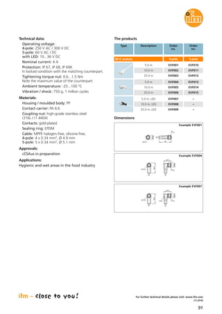
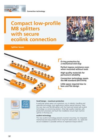
![93
(11.2016)
For further technical data please go to: www.ifm.com
Technical data:
Operating voltage:
with LED 10...30 V DC
Nominal current:
total max. current rating 6 A
max. 2 A per location
with M12 connection
total max. current rating 2 A
max. 2 A per location
Protection: cable connection IP 65, IP 67, IP 68
connector IP 65, IP 67
in locked condition
with the matching counterpart.
Tightening torque M8 connector: 0.3...0.6 Nm,
adhere to the maximum value of the counterpart
Ambient temperature: -25...80 °C
Materials:
Housing: PUR
Contact carrier: PA
Fitting: CuZn/Ni
Contacts: gold-plated
Sealing ring: Viton
Cable: PUR, halogen-free
Applications:
Factory automation, machine tools,
hydraulics
Products
M8x1
17
20
4,54,5
30
16
129,5
1014,3
1122
Dimensions
Example EBC054
M12x1
17
23,7
4,54,5
30
16
85,4
574,3
M8x1
1122
Example EBC050
Splitter with cable connection · LED · PNP
EBC048
EBC051
EBC049
EBC052
4
4
2 and 4
2 and 4
5
10
5
10
EBC054
EBC056
EBC055
EBC057
4
4
2 and 4
2 and 4
5
10
5
10
EBC136
EBC137
4
4
5
10
M12, 8-pole
M12, 12-pole
EBC0504
M16, 8-pole EBC0532 and 4
M12, 12-pole EBC1384
Type Signals
on pin
Order no.Connection/
Cable
[m]
Splitter with connector · LED · PNP
EBC1394Connection technology
Type Description Order
no.
Socket, M12, 8-pole
10 m black, PUR cable
Socket, M12, 8-pole
5 m black, PUR cable
Socket, M12, 8-pole
10 m black, PUR cable
Socket, M16, 8-pole
5 m black, PUR cable
Socket, M16, 8-pole
10 m black, PUR cable
E11311
E11232
E12260
E11226
E11227
Socket, M12, 12-pole,
5 m black, PUR cable
E12502
Socket, M12, 12-pole,
10 m black, PUR cable
E12503
Socket, M12, 12-pole,
15 m black, PUR cable
E12504
Socket, M12, 12-pole,
5 m black, PUR cable
E12457
Socket, M12, 12-pole,
10 m black, PUR cable
E12505
Socket, M12, 12-pole,
15 m black, PUR cable
E12506](https://image.slidesharecdn.com/ifm-product-news-2016-2017-en-170131091759/85/Newsbook-2016-2017-English-92-320.jpg)

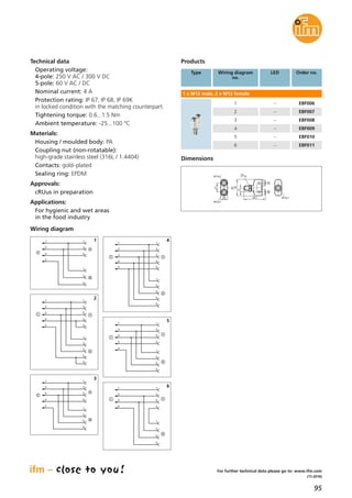
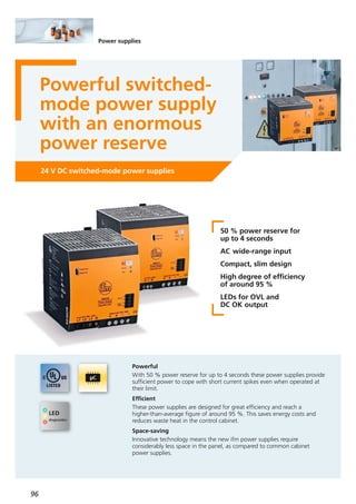
![97
(04.2016)
24 V DC switched-mode power supplies for rail mounting
Output current
permanent / peak
at 24 V DC
Output voltage
[V]
Input voltage
[V AC]
Output
DC OK signal
Efficiency
(120 / 230 V AC)
[%]
Order
no.
40 A / 60 A 24...28 DC; adjustable 100...240 Relay93.6 / 94.6 E84016
40 A / 60 A 24...28 DC; adjustable 3 x 380...480 Relay95.3 / 95.2 E84036
Further technical data
Functions and advantages
Power reserve
These power supplies provide an excellent power
reserve of 50 percent for up to four seconds to cope
with short current loads.
Inrush current limitation
Instead of an inrush current limitation with a simple
NTC element, charging the capacitors of the new
ifm switched-mode power supplies is microprocessor-
controlled. This allows the selectivity of fuses protecting
the inputs on the primary side and saves wiring costs.
Long bridging times
The voltage supply is ensured for several milliseconds if
the mains voltage briefly fails, e.g. caused by switching
operations in the supply network.
Wide operating temperature range
ifm switched-mode power supplies provide the specific
nominal power across the entire temperature range.
Derating only has to be taken into account above an
operating temperature of 60 °C.
Double terminal
All 24 V switched-mode power supplies are equipped
with double terminals. This simplifies wiring and provides
more clarity in the control cabinet.
Dimensions
119,3
354
132,6
127,6
1
2
3
2
3
4
5
6
1
N L PE
125
13
14
15
16
124
130,5
E84016
119
354
130,7
127,1
2
3
4
5
6
1
L1 L2 L3 PE
110
13
14
15
16
124
130,5
E84036
1) Jumper ”individual/parallel operation“
2) Potentiometer 24...28 V DC
3) LED DC OK
4) LED overload
5) Terminals DC OK signal
6) Terminal shut-down input
For further technical details please visit: www.ifm.com
Output power / [W]
peak
960 /
1440
Ambient temperature [°C] -25...70
Display LED
1 x DC OK
1 x overload
Shut-down
Controlled
switch-off of the
output voltage
Frequency range [Hz] 47...64
Protection IP 20
Short-circuit proof •
Overload protection •](https://image.slidesharecdn.com/ifm-product-news-2016-2017-en-170131091759/85/Newsbook-2016-2017-English-96-320.jpg)

![99
(04.2016)
For further technical details please visit: www.ifm.com
Modular installation
The system has a modular structure and consists of a
supply module to feed max. 40 A. The protection
modules can be mounted side by side. This is done via
a simple clip mechanism, completely without any
bridges, jumpers or the like.
Easy mounting and minimised wiring complexity save
cost and time. With the standard version the user can
connect up to 10 and with the IO-Link version up to
8 safety modules to the head module.
Versions
There is a standard and an IO-Link version. In addition
to the triggering mechanism, the modules feature an
LED for signalling if the module has triggered, if it is
active and to what extent it is utilised.
By means of a pushbutton each channel can be activated,
deactivated or set.
The feed module has an additional collective output to
provide a warning signal if a module has triggered.
More transparency with IO-Link
The IO-Link version has the same function; there is,
however, additional information about each channel:
Transfer to the IO-Link master:
• effective nominal current (1 byte cyclical)
• output voltage (acyclical)
• triggering counter (acyclical)
• current unit status (1 byte cyclical):
– short circuit
– overload
– undervoltage
– limit reached (80 % IN)
Transfer from the IO-Link master:
• activation/deactivation
• reset with triggering
• reset triggering counter
The modules are available in the fixed sizes 2 A, 4 A,
6 A, 8 A and 10 A. The fixed current values prevent
subsequent misuse by changing the max. current value.
InterfaceInputs
[V DC]
Order
no.
Supply module, standard
–24, 40 A DF1100
Nominal
current
[A]
–
Protection module, standard
–– DF12122 x 2
–– DF12142 x 4
–– DF12162 x 6
Operating voltage [V DC] 24 (18...30)
Switch-off characteristics
Time-current
characteristics
Temperature range [°C] -25...60
Connection technology
Push-in
incl. pusher
Installation DIN rail
Approvals
UL508 listed
(in preparation)
Fail-safe element
= nominal current
(e.g. 4 A = 4 A)
Switch-on capacity 20,000 μF
Switching status indication LED
Multi-colour,
signal contact via
feeding module
Further technical data
Supply module, IO-Link
IO-Link24, 40 A DF2100–
Protection module, IO-Link
IO-Link in combination
with head module
– DF22122 x 2
IO-Link in combination
with head module
– DF22142 x 4
IO-Link in combination
with head module
– DF22162 x 6
Accessories
Type Description Order
no.
USB IO-Link master for parameter setting
and analysis of units
Supported communication protocols
IO-Link (4.8, 38.4 and 230 kBits/s)
E30390
LINERECORDER SENSOR,
software for parameter setting and
setting up IO-Link sensors
QA0001
–– DF12081 x 8
–– DF12101 x 10
IO-Link in combination
with head module
– DF22081 x 8
IO-Link in combination
with head module
– DF22101 x 10](https://image.slidesharecdn.com/ifm-product-news-2016-2017-en-170131091759/85/Newsbook-2016-2017-English-98-320.jpg)
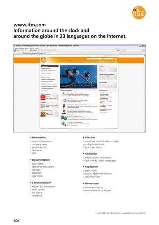
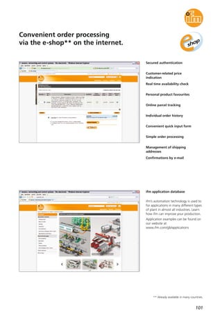


This document provides an overview of various sensor technologies from ifm electronic including inductive sensors, encoders, position sensors, infrared sensors, capacitive sensors, ultrasonic sensors, laser sensors, pressure sensors, flow sensors, temperature sensors, identification systems, and connection technologies. New products are highlighted such as inductive sensors that take a leap forward with one sensing range for all metals, the next generation of photoelectric sensors with distance display and easy setting, and IO-Link compatible sensors and components.


![Getting Started with Apache Spark: Big Data Made Simple [Free Meetup]](https://cdn.slidesharecdn.com/ss_thumbnails/apachesparkgettingstarted-260203175547-8361bcc3-thumbnail.jpg?width=640&height=640&fit=bounds)


