Download to read offline
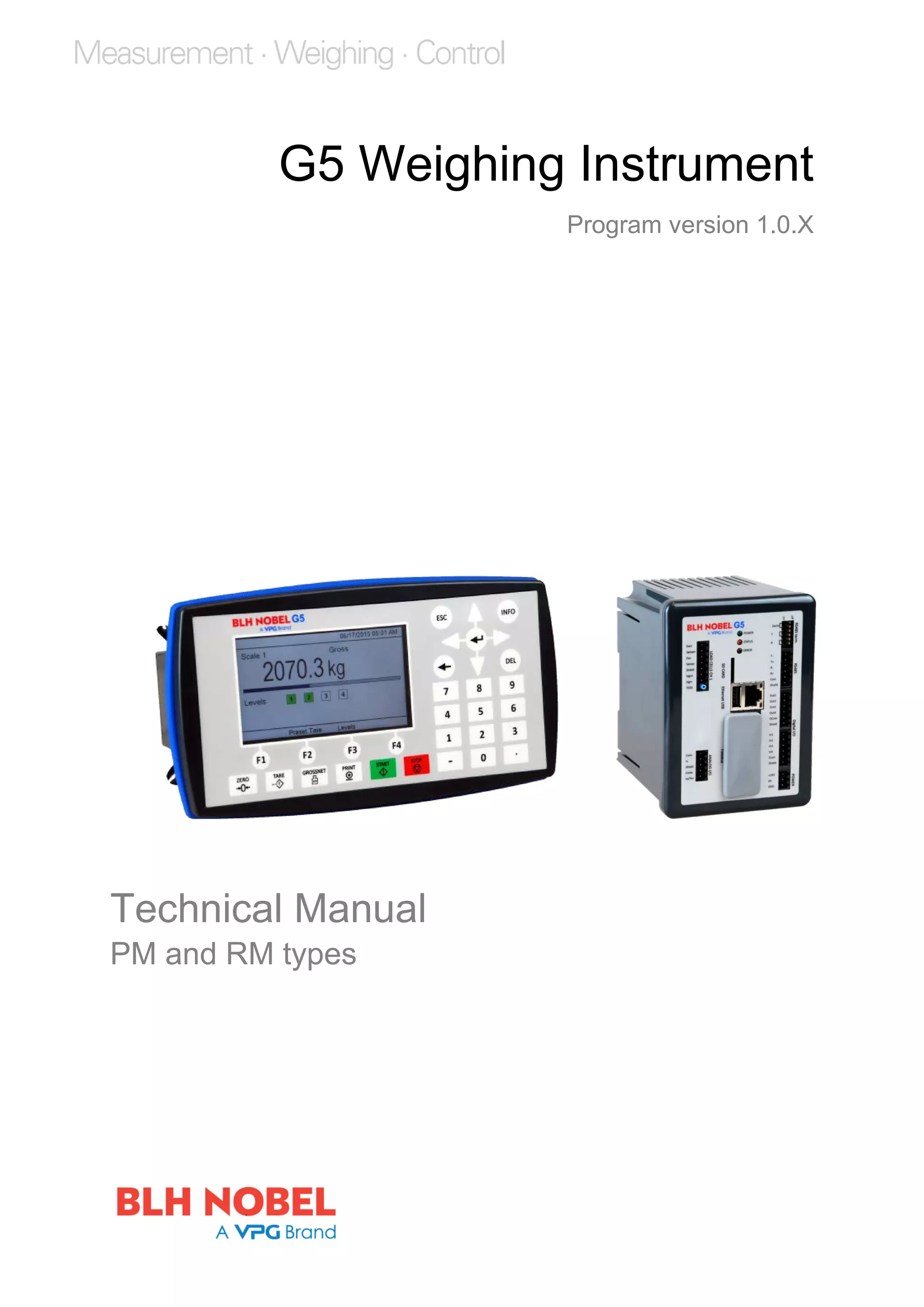


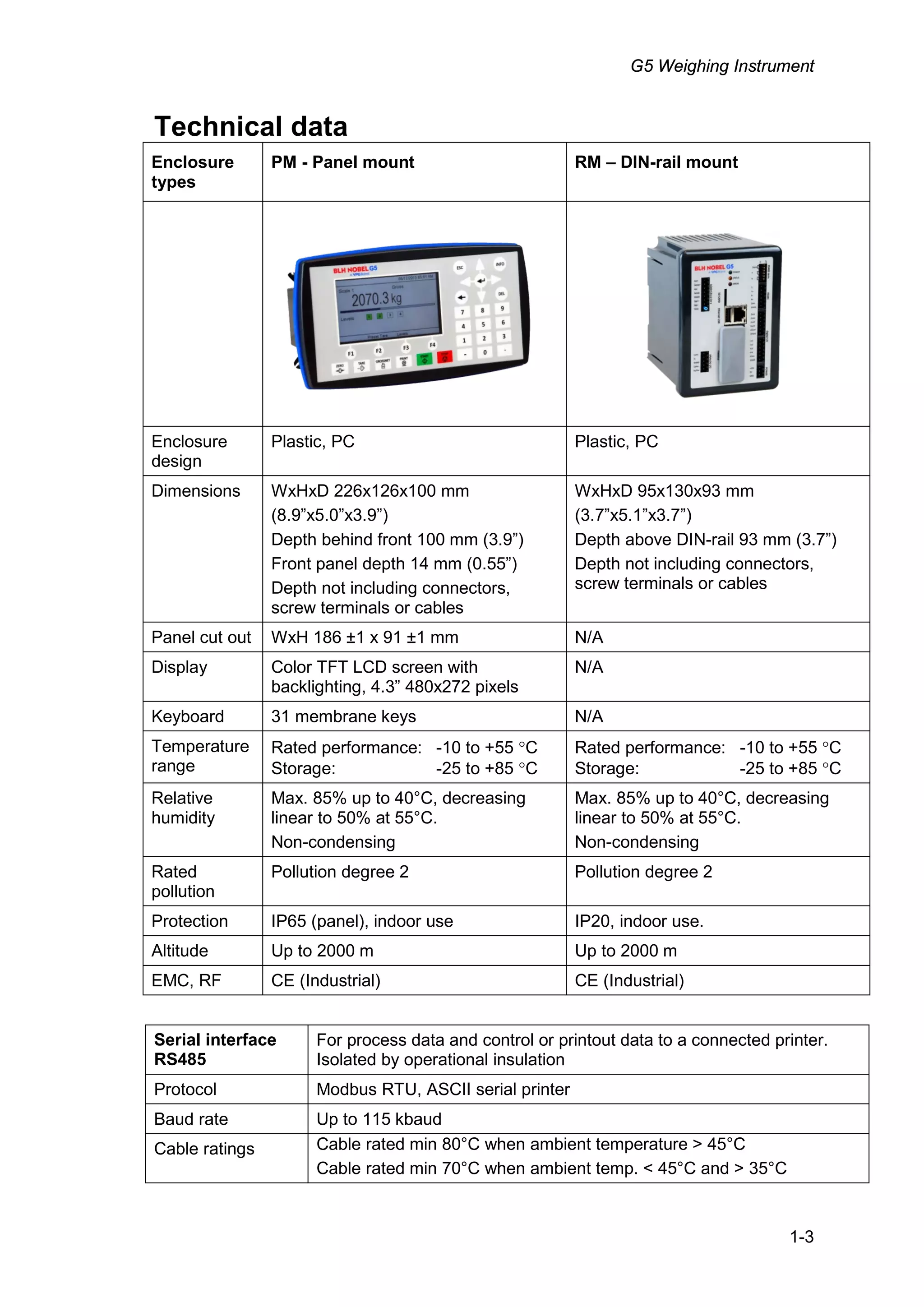
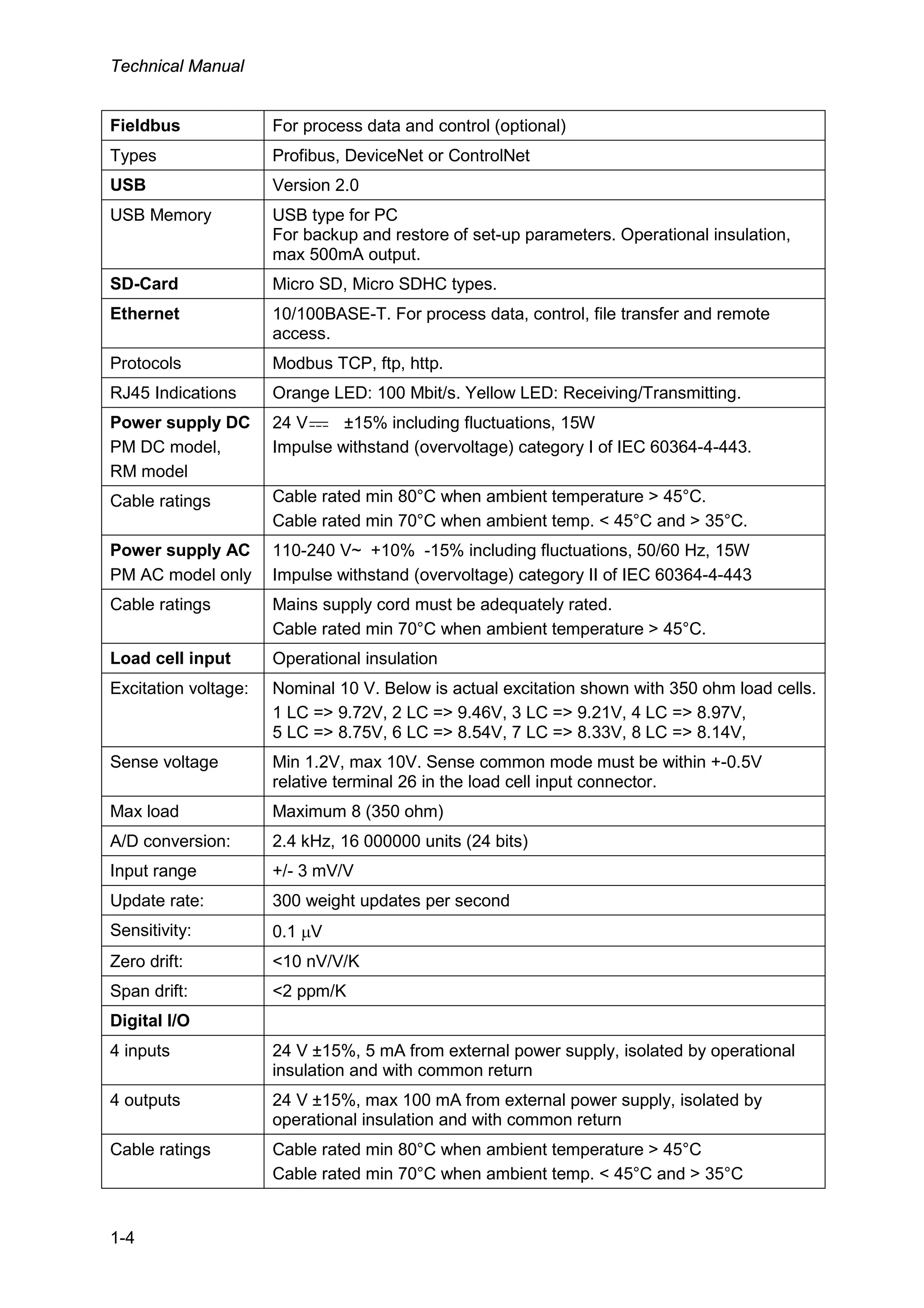


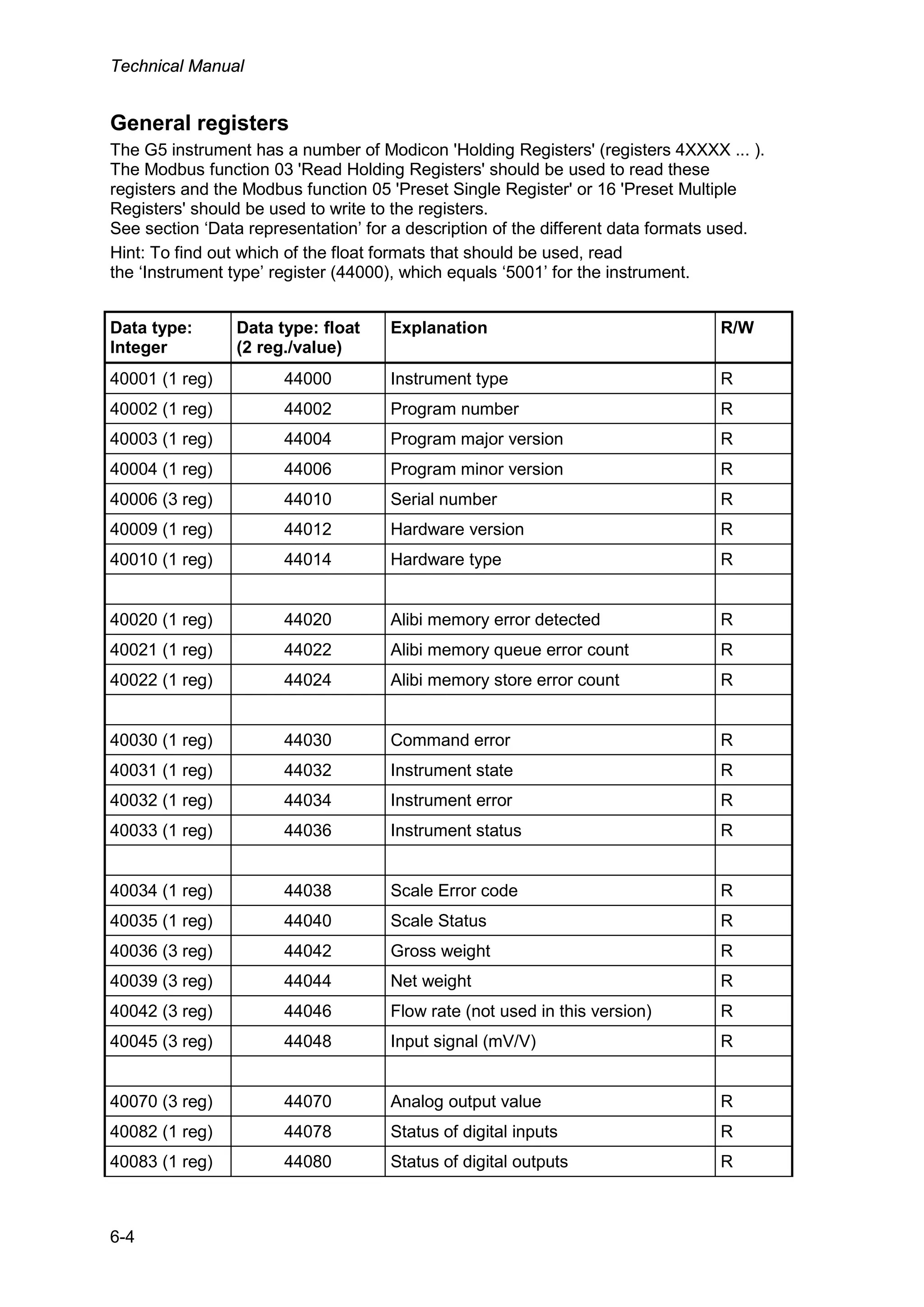


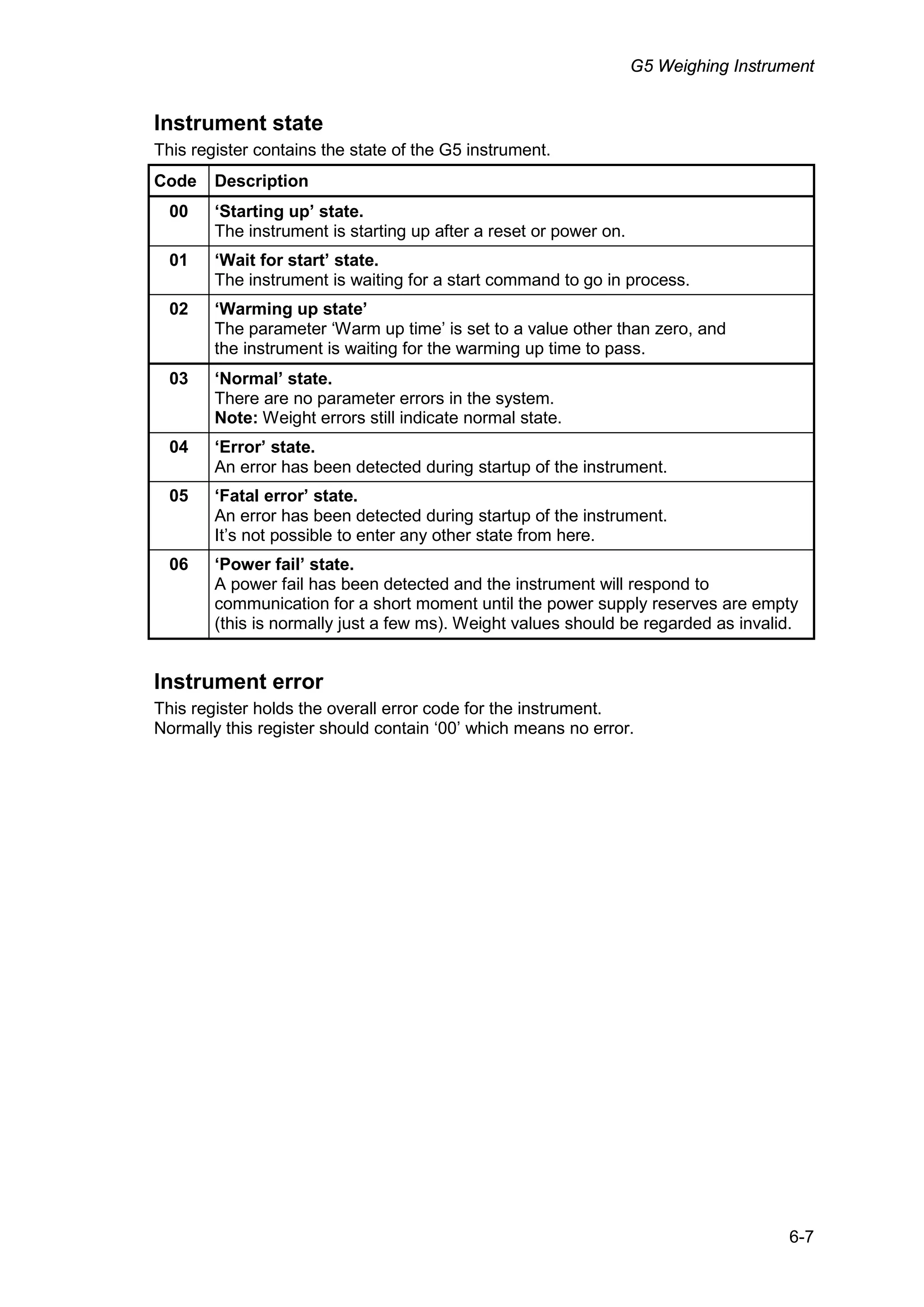

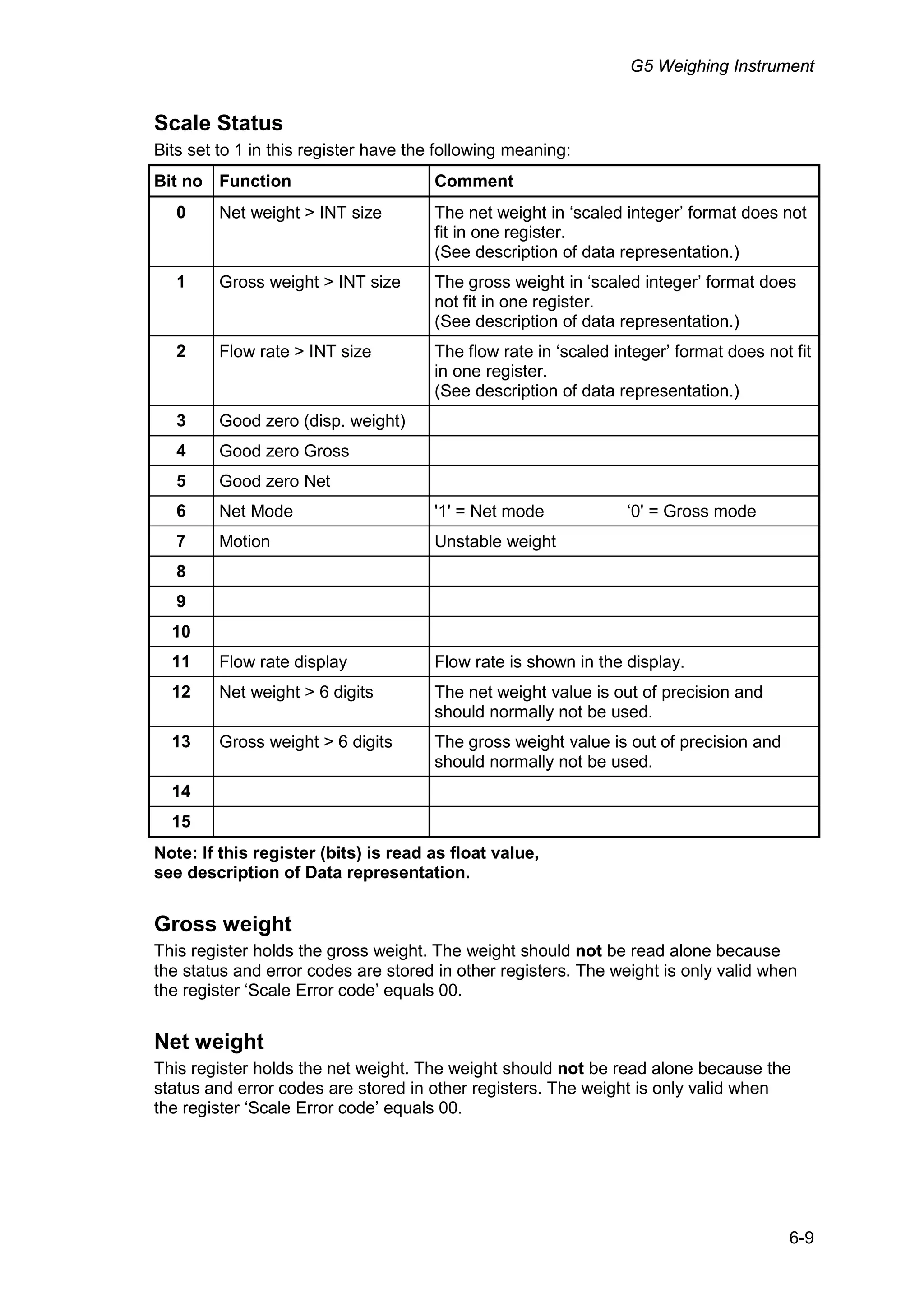
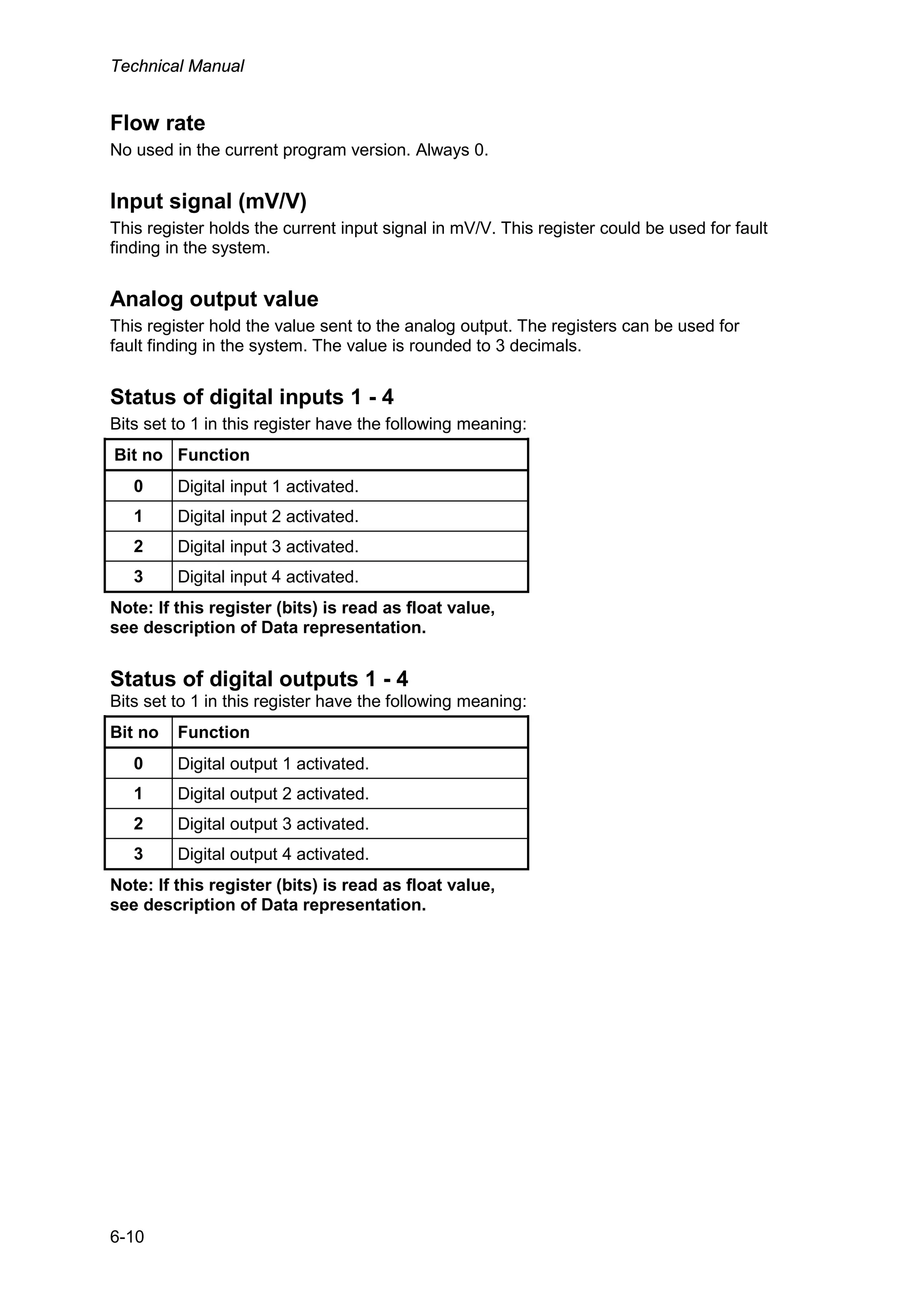


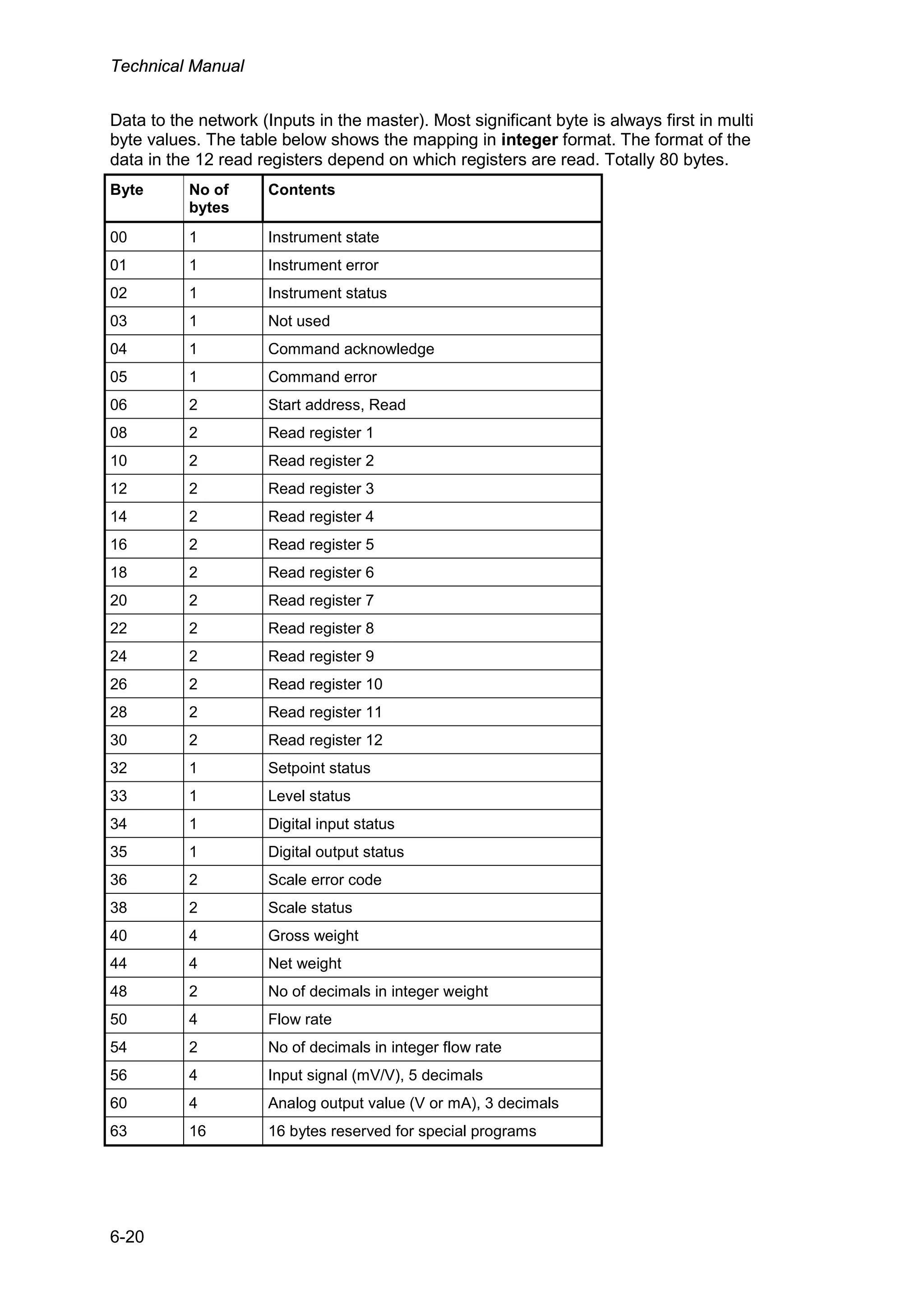
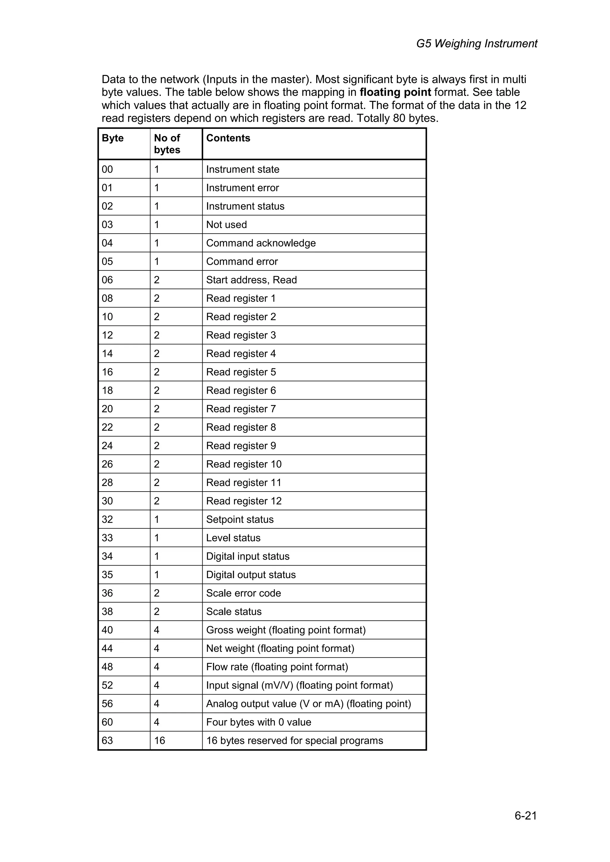
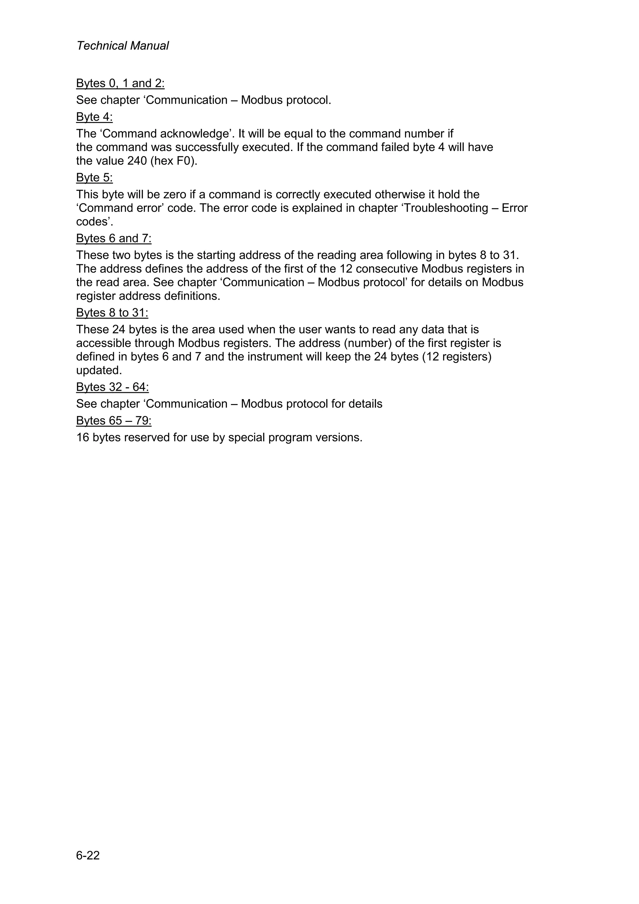


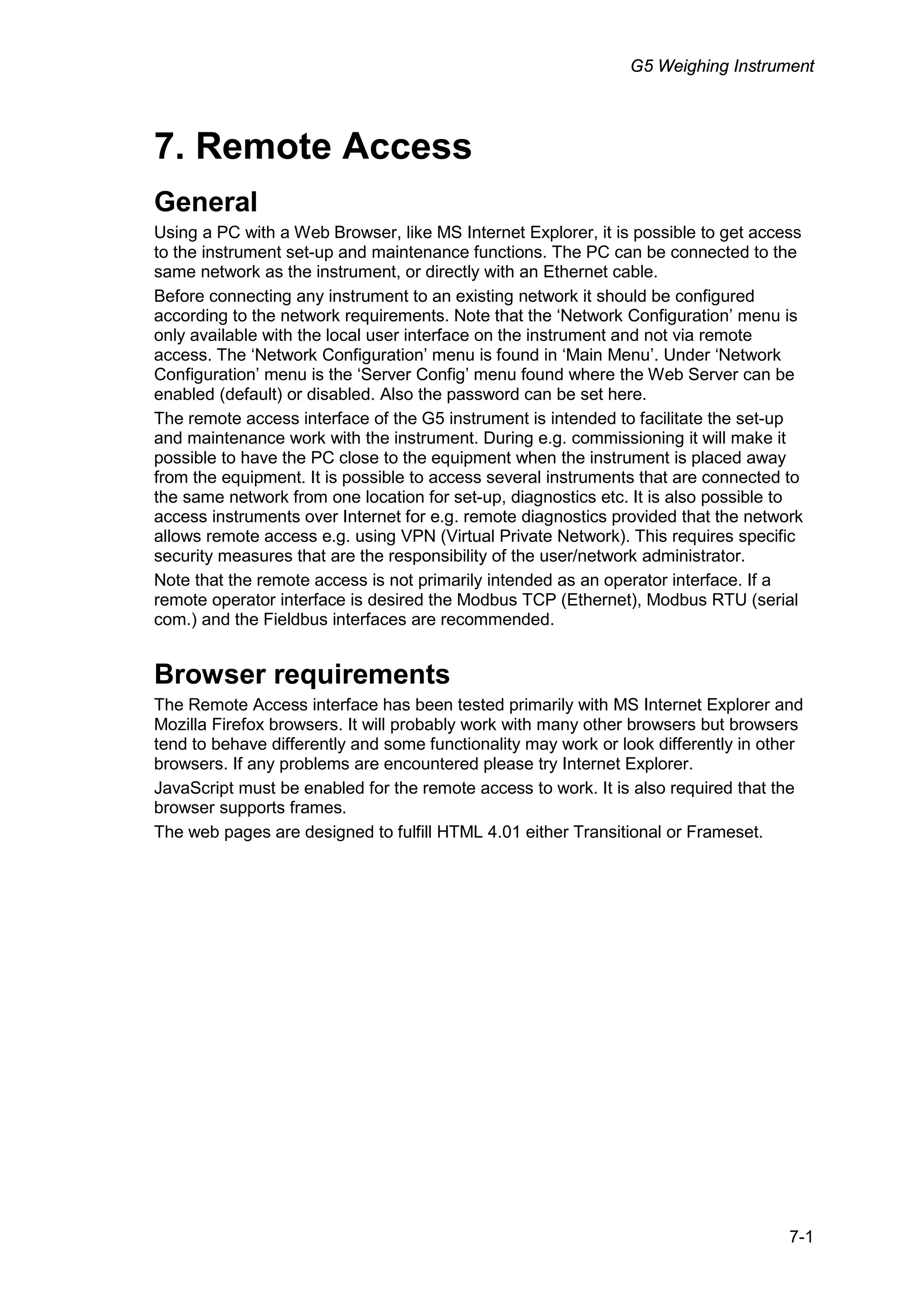


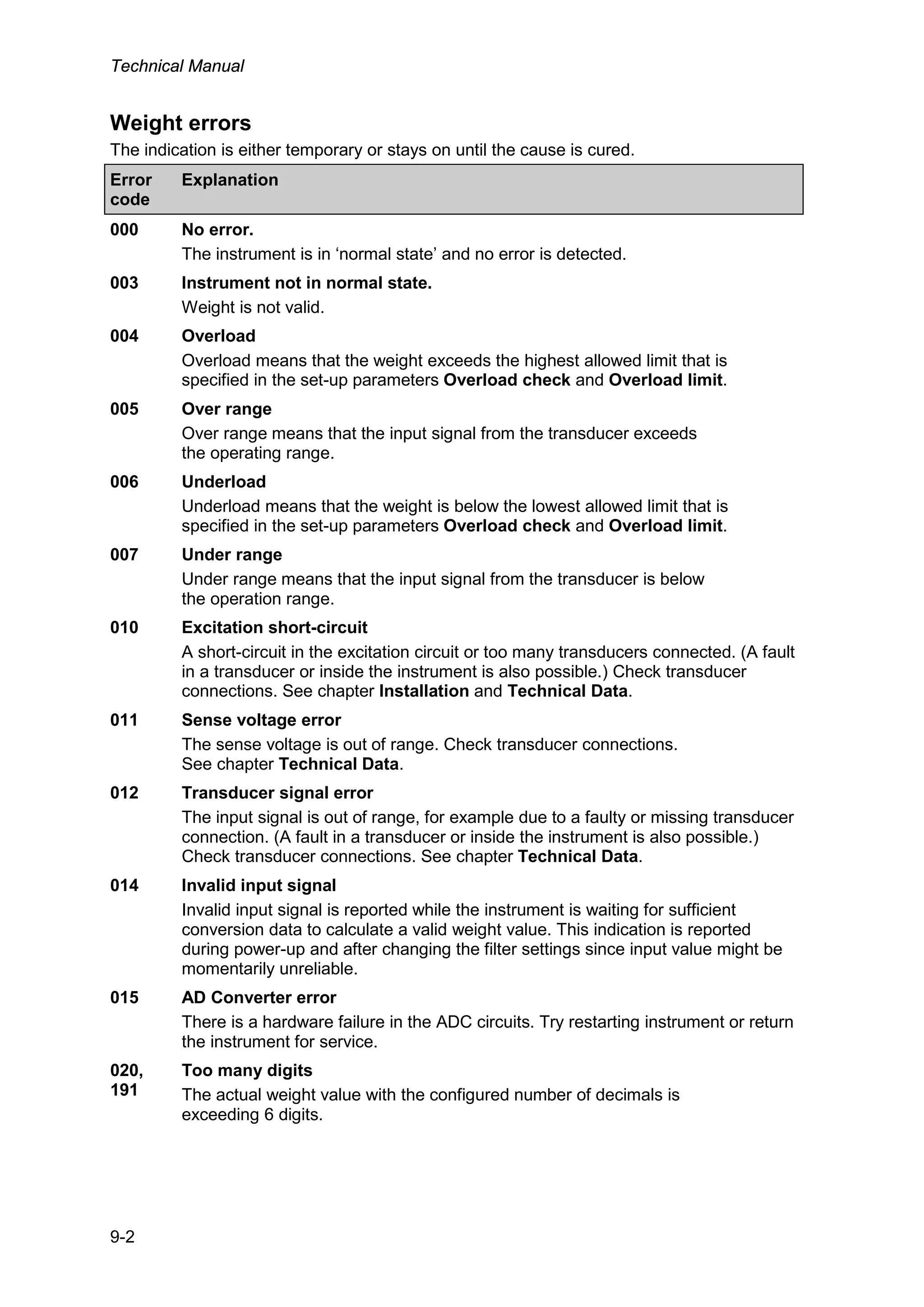


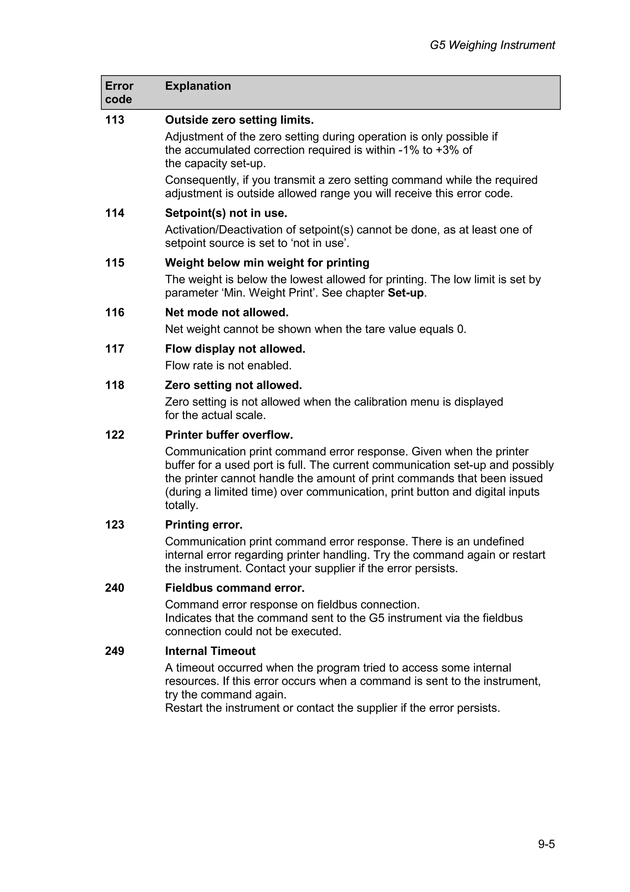
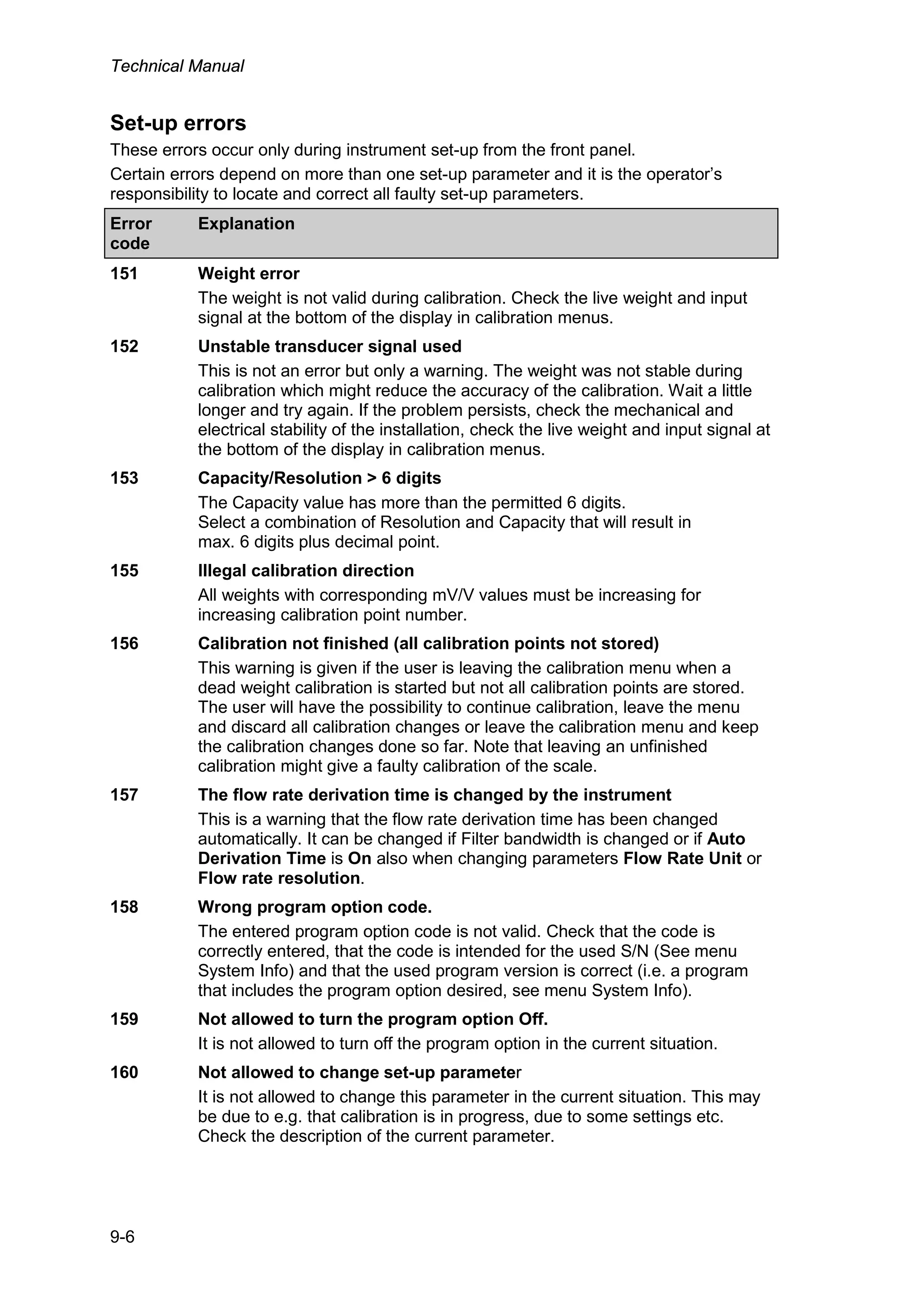


The G5 weighing instrument technical manual provides detailed instructions on installation, operation, communication, maintenance, and troubleshooting for the G5 series instruments. It supports both panel and DIN rail mounts and includes aspects like power supply specifications, calibration procedures, and error detection mechanisms. The manual emphasizes the importance of safety, qualified personnel for servicing, and appropriate usage in industrial systems.


