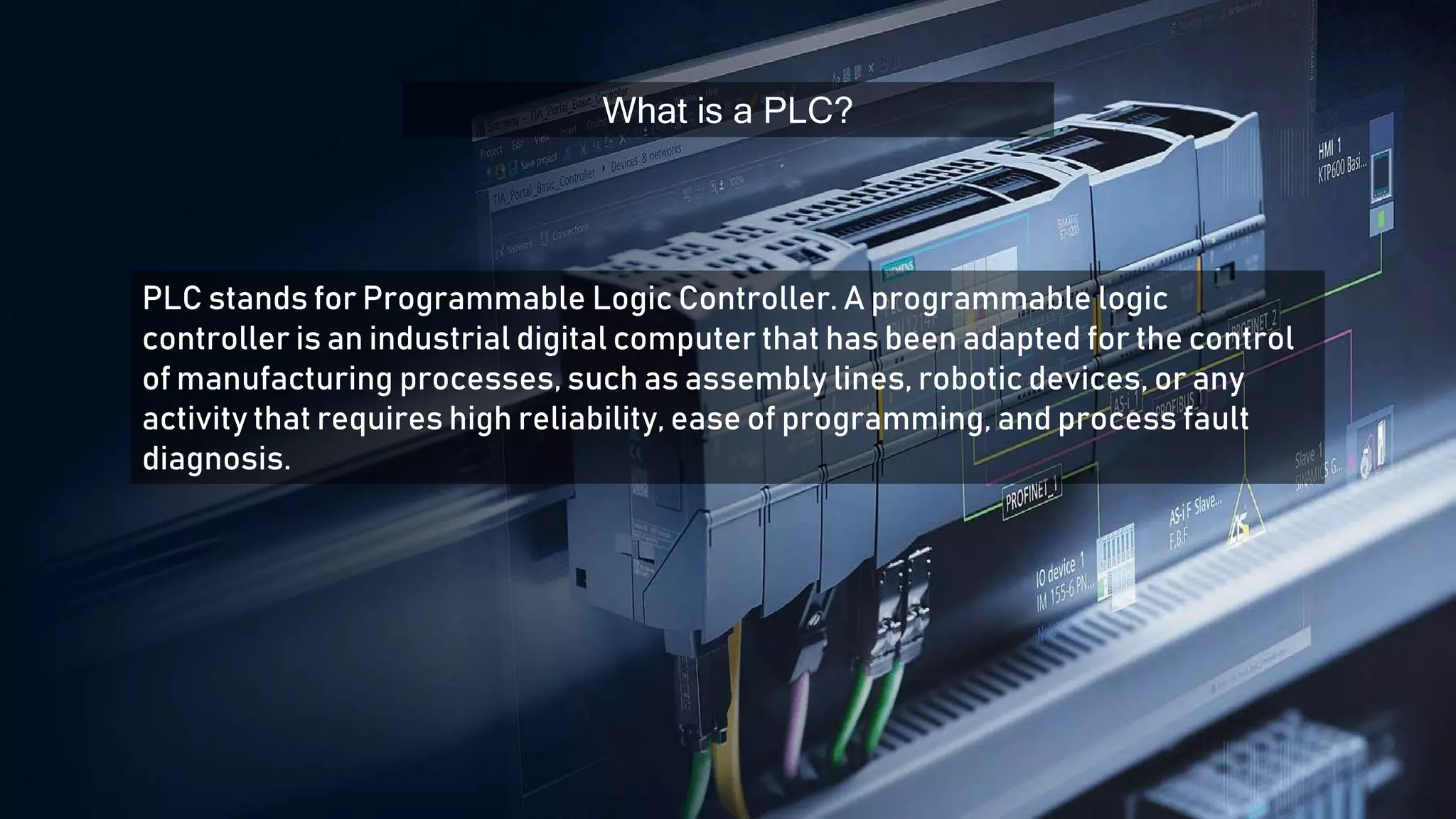
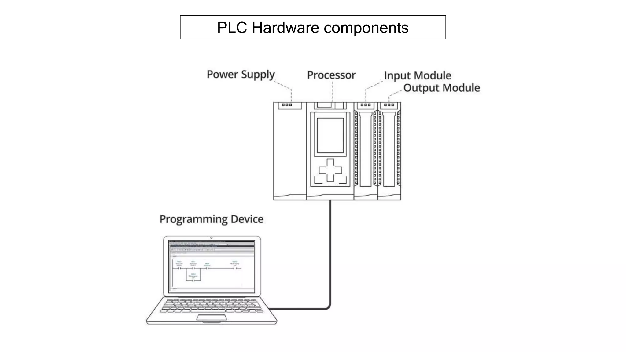
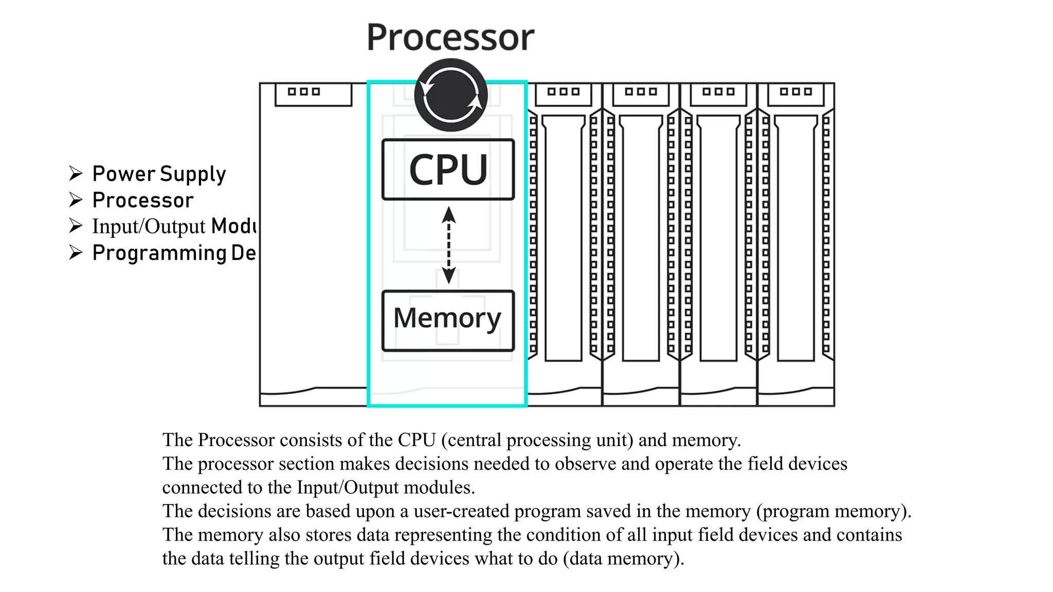
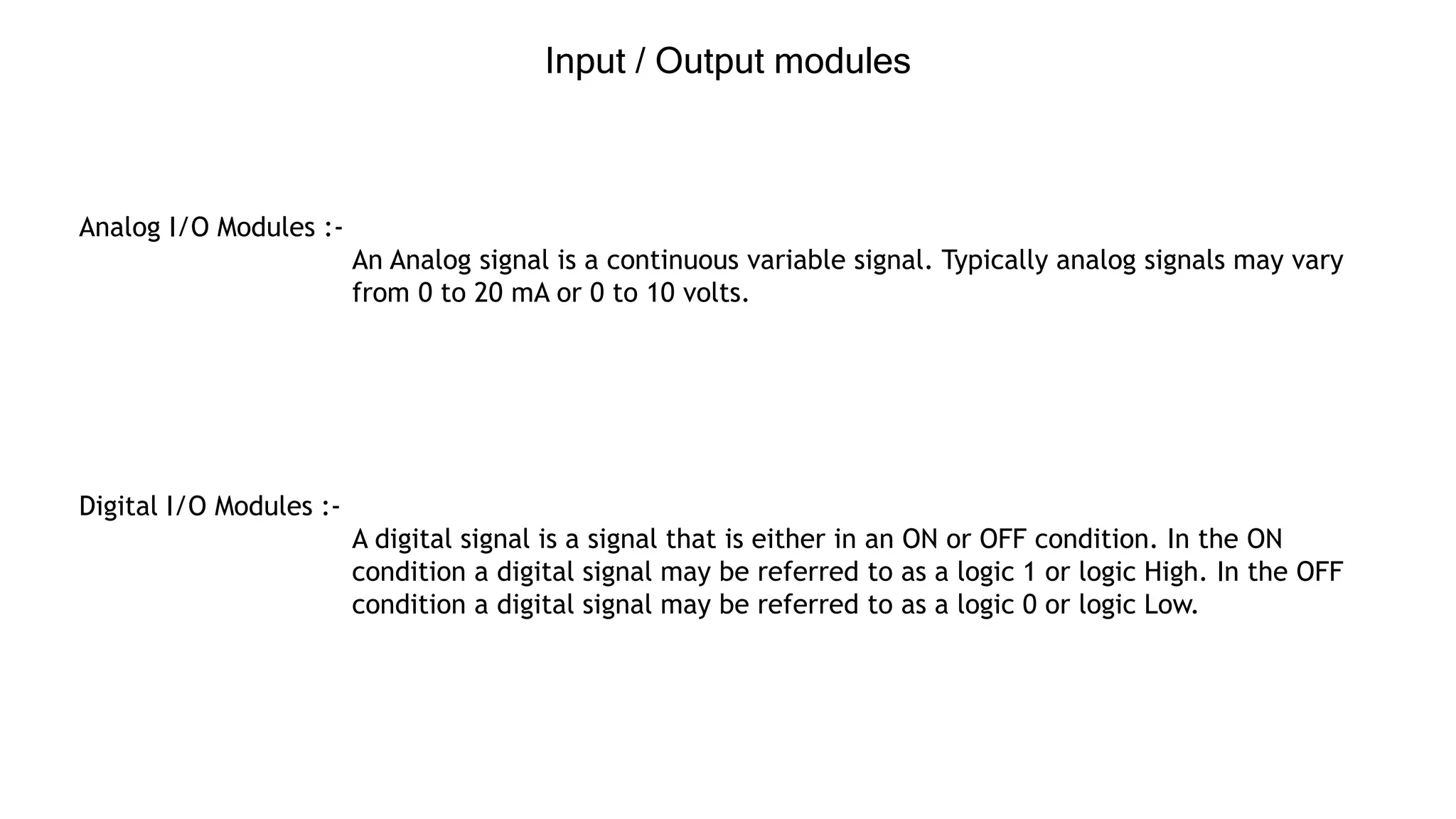
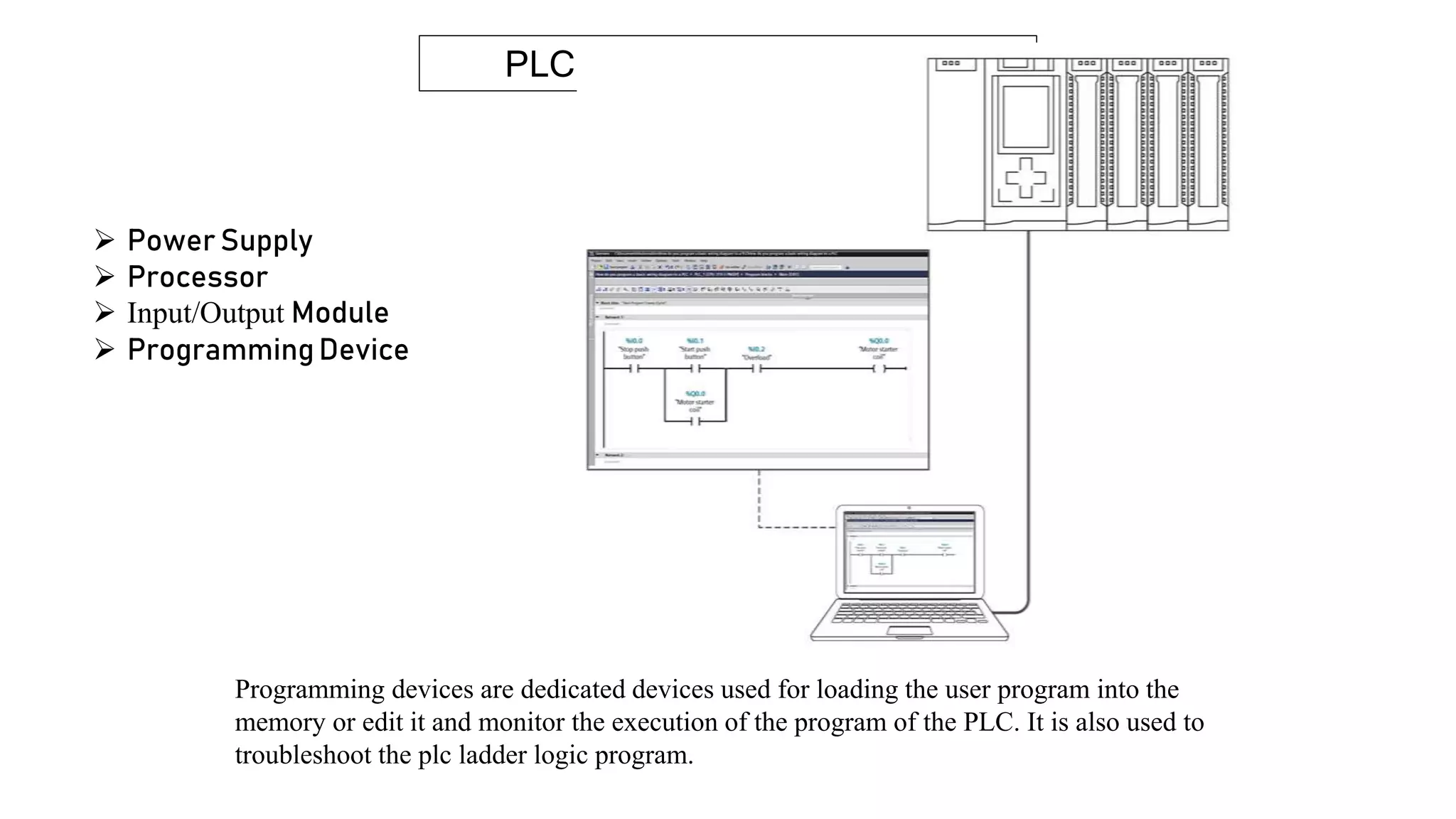
Topic :- Hardware components of PLC
Group mates:-
ChetanS Harihar
Dileep S
MadhanKumar N
What is a PLC?
PLC stands for Programmable Logic Controller. A programmable logic
controller is an industrial digital computer that has been adapted for the control
of manufacturing processes, such as assembly lines, robotic devices, or any
activity that requires high reliability, ease of programming, and process fault
diagnosis.
PLC Hardware components
 Power Supply
 Processor
 Input/Output Module
 ProgrammingDevice
The Power Supply is connected to AC mains for the supply voltage. The output of the
Power supply is a DC voltage used to power all of the other modules associated with the
PLC. Most of the PLC operates on 0 volts DC to 24 volts DC.
PLC Hardware components
 Power Supply
 Processor
 Input/Output Module
 ProgrammingDevice
The Processor consists of the CPU (central processing unit) and memory.
The processor section makes decisions needed to observe and operate the field devices
connected to the Input/Output modules.
The decisions are based upon a user-created program saved in the memory (program memory).
The memory also stores data representing the condition of all input field devices and contains
the data telling the output field devices what to do (data memory).
PLC Hardware components
 Power Supply
 Processor
 Input/Output Module
 ProgrammingDevice
The Input/Output modules are connected to digital or analog field devices (sensors, actuators).
Input field devices include switches, encoders, and transmitters for example.
Typical output field devices are relays, lamps, and proportional valves.
Input / Output modules
Analog I/O Modules :-
An Analog signal is a continuous variable signal. Typically analog signals may vary
from 0 to 20 mA or 0 to 10 volts.
Digital I/O Modules :-
A digital signal is a signal that is either in an ON or OFF condition. In the ON
condition a digital signal may be referred to as a logic 1 or logic High. In the OFF
condition a digital signal may be referred to as a logic 0 or logic Low.
Communication modules
Communication modules digitally transfer data between PLCs and other devices within the factory facility.
This becomes especially important as more factories are being equipped with Industrial Internet of Things
(IIoT). The modules bring both wired and wireless connectivity to and from the PLC.
PLC Communication modules are :-
 Serial
 Ethernet
 Field bus
 USB
 Modbus
PLC Hardware components
 Power Supply
 Processor
 Input/Output Module
 ProgrammingDevice
Programming devices are dedicated devices used for loading the user program into the
memory or edit it and monitor the execution of the program of the PLC. It is also used to
troubleshoot the plc ladder logic program.
plc hardware presentation.pptx

plc hardware presentation.pptx

  • 1.
    Topic :- Hardwarecomponents of PLC Group mates:- ChetanS Harihar Dileep S MadhanKumar N
  • 2.
    What is aPLC? PLC stands for Programmable Logic Controller. A programmable logic controller is an industrial digital computer that has been adapted for the control of manufacturing processes, such as assembly lines, robotic devices, or any activity that requires high reliability, ease of programming, and process fault diagnosis.
  • 3.
  • 4.
    PLC Hardware components Power Supply  Processor  Input/Output Module  ProgrammingDevice The Power Supply is connected to AC mains for the supply voltage. The output of the Power supply is a DC voltage used to power all of the other modules associated with the PLC. Most of the PLC operates on 0 volts DC to 24 volts DC.
  • 5.
    PLC Hardware components Power Supply  Processor  Input/Output Module  ProgrammingDevice The Processor consists of the CPU (central processing unit) and memory. The processor section makes decisions needed to observe and operate the field devices connected to the Input/Output modules. The decisions are based upon a user-created program saved in the memory (program memory). The memory also stores data representing the condition of all input field devices and contains the data telling the output field devices what to do (data memory).
  • 6.
    PLC Hardware components Power Supply  Processor  Input/Output Module  ProgrammingDevice The Input/Output modules are connected to digital or analog field devices (sensors, actuators). Input field devices include switches, encoders, and transmitters for example. Typical output field devices are relays, lamps, and proportional valves.
  • 7.
    Input / Outputmodules Analog I/O Modules :- An Analog signal is a continuous variable signal. Typically analog signals may vary from 0 to 20 mA or 0 to 10 volts. Digital I/O Modules :- A digital signal is a signal that is either in an ON or OFF condition. In the ON condition a digital signal may be referred to as a logic 1 or logic High. In the OFF condition a digital signal may be referred to as a logic 0 or logic Low.
  • 8.
    Communication modules Communication modulesdigitally transfer data between PLCs and other devices within the factory facility. This becomes especially important as more factories are being equipped with Industrial Internet of Things (IIoT). The modules bring both wired and wireless connectivity to and from the PLC. PLC Communication modules are :-  Serial  Ethernet  Field bus  USB  Modbus
  • 9.
    PLC Hardware components Power Supply  Processor  Input/Output Module  ProgrammingDevice Programming devices are dedicated devices used for loading the user program into the memory or edit it and monitor the execution of the program of the PLC. It is also used to troubleshoot the plc ladder logic program.