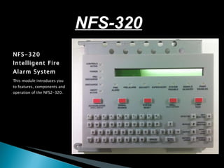
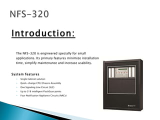
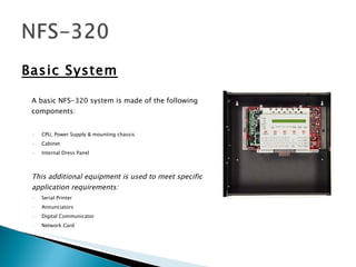
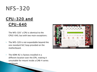
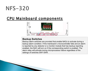
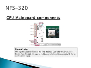
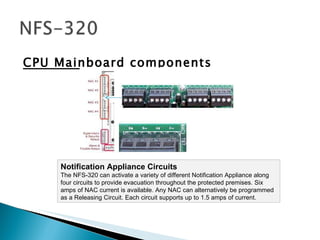
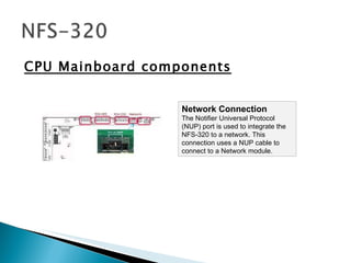
NFS-320 Intelligent Fire Alarm System This module introduces you to features, components and operation of the NFS2-320. NFS-320
Introduction: The NFS-320 is engineered specially for small applications. Its primary features minimize installation time, simplify maintenance and increase usability. System features Single Cabinet solution Quick-change CPU/Chassis Assembly One Signaling Line Circuit (SLC) Up to 318 intelligent FlashScan points Four Notification Appliance Circuits (NACs)
Basic System A basic NFS-320 system is made of the following components: CPU, Power Supply & mounting chassis Cabinet Internal Dress Panel This additional equipment is used to meet specific application requirements: Serial Printer Annunciators Digital Communicator Network Card
CPU-320 and CPU-640 The NFS-320´s CPU is identical to the CPU2-640, but with two main exceptions:  The NFS-320 is not expandable beyond the one standard SLC loop provided on the motherboard.  The KDM-R2 is factory installed in a different location over the CPU, making it unsuitable for mount inside a CAB-4 series enclosure.
CPU Mainboard components TB3: Battery Connection The NFS-320 requires a secondary power source of 24 VDC. The battery charger output  support 18 – 200 AH batteries.
CPU Mainboard components TB1: AC POWER: HOT – NEUTRAL – EARTH  Primary AC power source – 120 VAC, 50/60 Hz, 5.0 A from the voltage source. Use 12 AWG wire (max) with a 600 – volt rating.
CPU Mainboard components Backup Switches  Backup alarm switches are provided that enable NACs to activate during a backup alarm condition. If the mainboard´s microcontroller fails and an alarm is reported by any detector or a monitor module that has backup reporting enabled, the NAC will turn on if the corresponding switch is enabled. The alarm relay will activate during microprocessor failure regardless of the settings of switches SW1-SW4.
CPU Mainboard components System switches  Onboard switches are provided for the execution of Acknowledge, Silence and Reset functions during service and maintenance when a local keyboard/display has not been installed on the CPU-320.
CPU Mainboard components KDM Connector  The KDM-R2 Keyboard Display interfaces to the CPU-320 via a ribbon cable on J7.
CPU Mainboard components Status LEDs Onboard LEDs annunciate the status of critical system status.
CPU Mainboard components The Aux Inputs  The CPU-320 contains an input for the receipt of auxiliary trouble signals on J6. A short on this input generates a trouble signal.
CPU Mainboard components Zone Coder This input is used to interface the NFS-320 to a UZC-256 Universal Zone Coder.  Note: The UZC-256 requires 5 VDC power which must be supplied by TB-2 or an auxiliary power supply.
CPU Mainboard components Notification Appliance Circuits The NFS-320 can activate a variety of different Notification Appliance along four circuits to provide evacuation throughout the protected premises. Six amps of NAC current is available. Any NAC can alternatively be programmed as a Releasing Circuit. Each circuit supports up to 1.5 amps of current.
CPU Mainboard components Relays Form-C  Security  and  Supervisory  relays are provided onboard the CPU-320. These relays are rated for 2 A at 30 VDC (resistive).
CPU Mainboard components DC Accessories Power Outputs Terminal TB2 supplies two power-limited outputs for powering local accessories.  One 24 VDC (nominal) nonressetable circuit provides up to 0-5 amps of current.  One 5 VDC (nominal) nonressetable circuit provides up to 0.15 amps.
CPU Mainboard components Power Outputs TB10 of the CPU-320 provides two power outputs, one resettable, and one non-resettable for powering external peripherals. Each output is power-limited but not supervised. Power Supervision Relays must be used to supervise the power at the end of these circuits.  Each output is power-limited but not supervised. Relays must be used to supervise the power at the end of these circuits.
CPU Mainboard components EIA-485 Circuits TB11 provides two outputs for the connection of two classes of remote annunciators.
CPU Mainboard components Printer Connection  A PRN series printer can be used to print a copy of all status changes within the control panel and time-stamp the printout with the time of day and date the event occurred. A custom cable with a DB-25 female connector is needed for connection to the control panel. The EIA-232 output is power-limited but not supervised.
CPU Mainboard components Network Connection  The Notifier Universal Protocol (NUP) port is used to integrate the NFS-320 to a network. This connection uses a NUP cable to connect to a Network module.
CPU Mainboard components Verifire Tools Connections (J2, J3, NUP) Two USB port types are provided to allow the Verifire Tools programming utility to upload/download the operating program. For computers without a USB port, connection can be made between the PC´s serial port and CPU´s J1 NUP port.
CPU Mainboard components NACs and DC Power Outputs NOTE: The NACs and DC Power Outputs share a pool of 6 amps in alarm or 3 amps during standby.
SLC Loop  The Signaling Line Circuit (SLC) of the NFS-320 is integral to the CPU-320. This circuit provides the system with a standard capability to support up to 159 Intelligent detectors and 159 Addressable Modules.  B(+)  A(+)  B(-)  A(-)
CPU Mainboard components JP1 Ground Fault Jumper. Cut to permanently disable ground fault sensing on the SLC Loop.
CPU Mainboard components 200 mA Jumper Cutting jumper JP2 reduces the available current on the SLC loop in applications where this additional power is needed elsewhere. This restricts SLC operation to CLIP devices only.  It is recommended that this jumper NEVER be cut.
CPU Mainboard components LED10 This micro-LED indicates that a Ground Fault condition exists on the SLC Loop.
CPU Mainboard components Earth Fault LED LED3 indicates that a general board ground fault condition exists somewhere within the mainboard.
CPU Mainboard components Ground Fault Switch A Ground Fault Disable/Enable switch (SW1) is provided for applications in which another component of the system, such as another power supply or fire alarm control panel, is providing ground fault detection.
UDACT DIGITAL COMMUNICATOR The UDACT is a digital alarm communicator and transmitter for reporting to a central station. The NFS-320 supports the installation of the UDACT underneath and the right of the keypad.
KDM-R2 The NFS-320 has a standard item the same KDM-R2 that is an option with the NFS2-640.
Voice Evacuation The NFS-320 can interface to an NFV-25/50ZS Fire Voice Evacuation System to control messages and control circuit activation.  This action is accomplished through software zone programming and an EIA-485 connection to the voice system, making it ideal for small, single channel voice evacuation applications.  For application requiring more than eight speakers circuits, the NFV-25/50ZS can be expanded using NFV-25/50DAZS Distribuited Audio Panels, providing up to twenty for speakers circuits that can be controlled via the serial communication link.

NFS-320

  • 1.
    NFS-320 Intelligent FireAlarm System This module introduces you to features, components and operation of the NFS2-320. NFS-320
  • 2.
    Introduction: The NFS-320is engineered specially for small applications. Its primary features minimize installation time, simplify maintenance and increase usability. System features Single Cabinet solution Quick-change CPU/Chassis Assembly One Signaling Line Circuit (SLC) Up to 318 intelligent FlashScan points Four Notification Appliance Circuits (NACs)
  • 3.
    Basic System Abasic NFS-320 system is made of the following components: CPU, Power Supply & mounting chassis Cabinet Internal Dress Panel This additional equipment is used to meet specific application requirements: Serial Printer Annunciators Digital Communicator Network Card
  • 4.
    CPU-320 and CPU-640The NFS-320´s CPU is identical to the CPU2-640, but with two main exceptions: The NFS-320 is not expandable beyond the one standard SLC loop provided on the motherboard. The KDM-R2 is factory installed in a different location over the CPU, making it unsuitable for mount inside a CAB-4 series enclosure.
  • 5.
    CPU Mainboard componentsTB3: Battery Connection The NFS-320 requires a secondary power source of 24 VDC. The battery charger output support 18 – 200 AH batteries.
  • 6.
    CPU Mainboard componentsTB1: AC POWER: HOT – NEUTRAL – EARTH Primary AC power source – 120 VAC, 50/60 Hz, 5.0 A from the voltage source. Use 12 AWG wire (max) with a 600 – volt rating.
  • 7.
    CPU Mainboard componentsBackup Switches Backup alarm switches are provided that enable NACs to activate during a backup alarm condition. If the mainboard´s microcontroller fails and an alarm is reported by any detector or a monitor module that has backup reporting enabled, the NAC will turn on if the corresponding switch is enabled. The alarm relay will activate during microprocessor failure regardless of the settings of switches SW1-SW4.
  • 8.
    CPU Mainboard componentsSystem switches Onboard switches are provided for the execution of Acknowledge, Silence and Reset functions during service and maintenance when a local keyboard/display has not been installed on the CPU-320.
  • 9.
    CPU Mainboard componentsKDM Connector The KDM-R2 Keyboard Display interfaces to the CPU-320 via a ribbon cable on J7.
  • 10.
    CPU Mainboard componentsStatus LEDs Onboard LEDs annunciate the status of critical system status.
  • 11.
    CPU Mainboard componentsThe Aux Inputs The CPU-320 contains an input for the receipt of auxiliary trouble signals on J6. A short on this input generates a trouble signal.
  • 12.
    CPU Mainboard componentsZone Coder This input is used to interface the NFS-320 to a UZC-256 Universal Zone Coder. Note: The UZC-256 requires 5 VDC power which must be supplied by TB-2 or an auxiliary power supply.
  • 13.
    CPU Mainboard componentsNotification Appliance Circuits The NFS-320 can activate a variety of different Notification Appliance along four circuits to provide evacuation throughout the protected premises. Six amps of NAC current is available. Any NAC can alternatively be programmed as a Releasing Circuit. Each circuit supports up to 1.5 amps of current.
  • 14.
    CPU Mainboard componentsRelays Form-C Security and Supervisory relays are provided onboard the CPU-320. These relays are rated for 2 A at 30 VDC (resistive).
  • 15.
    CPU Mainboard componentsDC Accessories Power Outputs Terminal TB2 supplies two power-limited outputs for powering local accessories. One 24 VDC (nominal) nonressetable circuit provides up to 0-5 amps of current. One 5 VDC (nominal) nonressetable circuit provides up to 0.15 amps.
  • 16.
    CPU Mainboard componentsPower Outputs TB10 of the CPU-320 provides two power outputs, one resettable, and one non-resettable for powering external peripherals. Each output is power-limited but not supervised. Power Supervision Relays must be used to supervise the power at the end of these circuits. Each output is power-limited but not supervised. Relays must be used to supervise the power at the end of these circuits.
  • 17.
    CPU Mainboard componentsEIA-485 Circuits TB11 provides two outputs for the connection of two classes of remote annunciators.
  • 18.
    CPU Mainboard componentsPrinter Connection A PRN series printer can be used to print a copy of all status changes within the control panel and time-stamp the printout with the time of day and date the event occurred. A custom cable with a DB-25 female connector is needed for connection to the control panel. The EIA-232 output is power-limited but not supervised.
  • 19.
    CPU Mainboard componentsNetwork Connection The Notifier Universal Protocol (NUP) port is used to integrate the NFS-320 to a network. This connection uses a NUP cable to connect to a Network module.
  • 20.
    CPU Mainboard componentsVerifire Tools Connections (J2, J3, NUP) Two USB port types are provided to allow the Verifire Tools programming utility to upload/download the operating program. For computers without a USB port, connection can be made between the PC´s serial port and CPU´s J1 NUP port.
  • 21.
    CPU Mainboard componentsNACs and DC Power Outputs NOTE: The NACs and DC Power Outputs share a pool of 6 amps in alarm or 3 amps during standby.
  • 22.
    SLC Loop The Signaling Line Circuit (SLC) of the NFS-320 is integral to the CPU-320. This circuit provides the system with a standard capability to support up to 159 Intelligent detectors and 159 Addressable Modules. B(+) A(+) B(-) A(-)
  • 23.
    CPU Mainboard componentsJP1 Ground Fault Jumper. Cut to permanently disable ground fault sensing on the SLC Loop.
  • 24.
    CPU Mainboard components200 mA Jumper Cutting jumper JP2 reduces the available current on the SLC loop in applications where this additional power is needed elsewhere. This restricts SLC operation to CLIP devices only. It is recommended that this jumper NEVER be cut.
  • 25.
    CPU Mainboard componentsLED10 This micro-LED indicates that a Ground Fault condition exists on the SLC Loop.
  • 26.
    CPU Mainboard componentsEarth Fault LED LED3 indicates that a general board ground fault condition exists somewhere within the mainboard.
  • 27.
    CPU Mainboard componentsGround Fault Switch A Ground Fault Disable/Enable switch (SW1) is provided for applications in which another component of the system, such as another power supply or fire alarm control panel, is providing ground fault detection.
  • 28.
    UDACT DIGITAL COMMUNICATORThe UDACT is a digital alarm communicator and transmitter for reporting to a central station. The NFS-320 supports the installation of the UDACT underneath and the right of the keypad.
  • 29.
    KDM-R2 The NFS-320has a standard item the same KDM-R2 that is an option with the NFS2-640.
  • 30.
    Voice Evacuation TheNFS-320 can interface to an NFV-25/50ZS Fire Voice Evacuation System to control messages and control circuit activation. This action is accomplished through software zone programming and an EIA-485 connection to the voice system, making it ideal for small, single channel voice evacuation applications. For application requiring more than eight speakers circuits, the NFV-25/50ZS can be expanded using NFV-25/50DAZS Distribuited Audio Panels, providing up to twenty for speakers circuits that can be controlled via the serial communication link.

Editor's Notes