Download to read offline


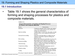
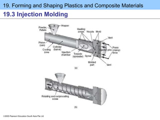
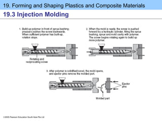
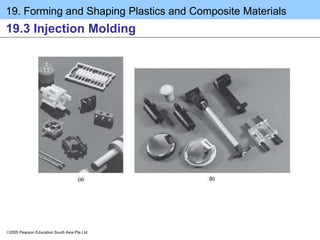
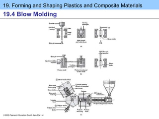

The document discusses various plastic forming processes including extrusion, injection molding, and blow molding. Extrusion is used to produce plastic rods, tubes, sheets and films through the use of a screw extruder. In injection molding, plastic pellets are melted and injected into a mold under high pressure to form complex parts. Blow molding uses extruded tubes that are expanded using air pressure to form hollow shapes like bottles.