Downloaded 69 times

![Plain and Reinforced Concrete I Experiment No. 2
4
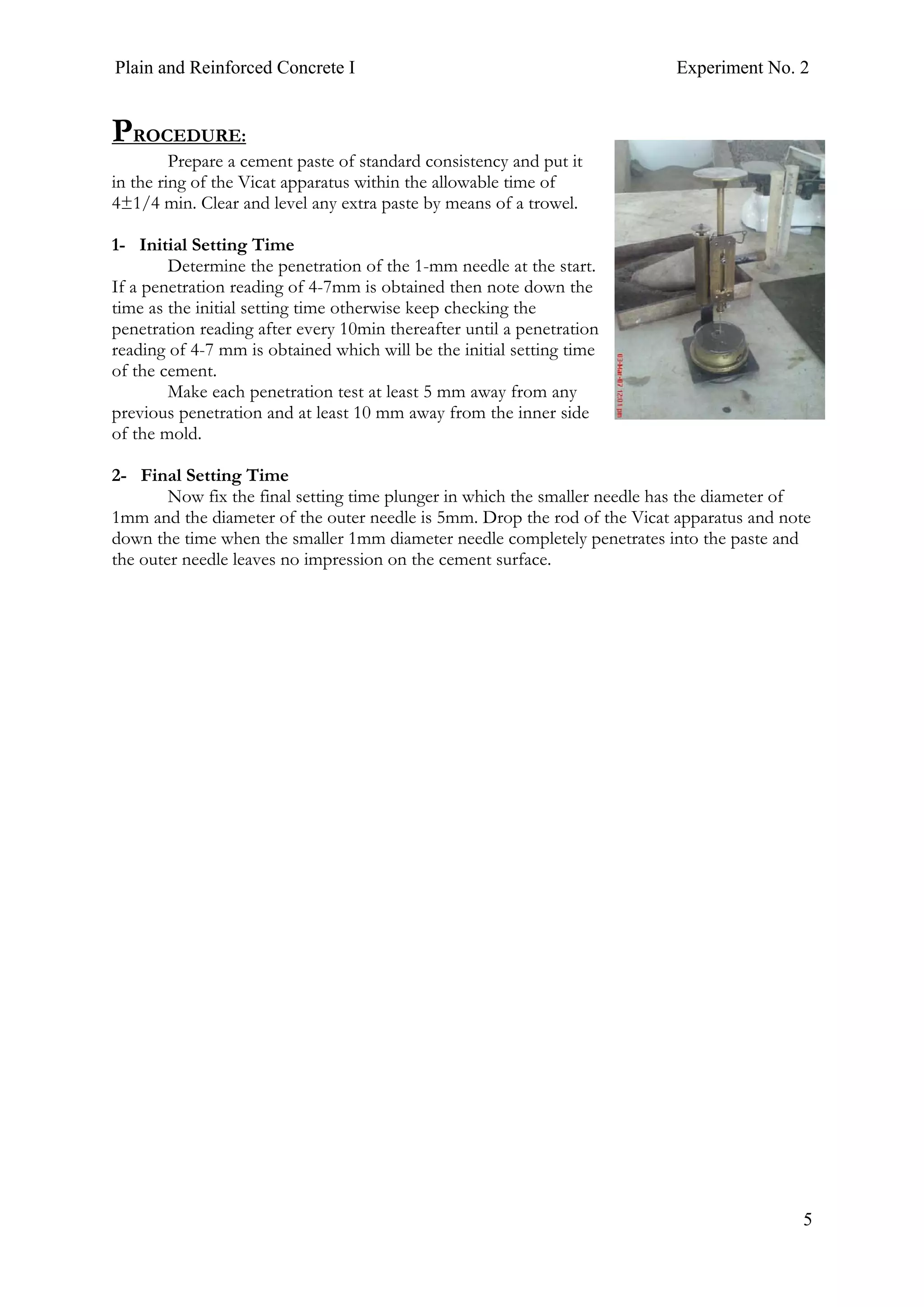
The time elapsed between the initial contact of cement and water and the time when a
1mm2
cross-section needle gives a reading between 4-7mm from the bottom in a standard Vicat
apparatus is known as initial setting time of that particular cement paste.
FINAL SETTING TIME
It is the time elapsed between the initial contact of cement and water and the time when
the smaller needle (1mm2
cross-section and 1mm deep) completely penetrates into the paste and
the outer metal attachment of 5mm diameter does not leave an impression on the cement paste.
According to specifications;
Maximum final setting time = 10hrs
Minimum final setting time = [90 + 1.2 (initial setting time)] min
TEST SPECIFICATIONS:
NEEDLE SIZES
1- For Initial Setting Time
1mm x 1mm cross-section
50mm length
2- For Final Setting Time
1mm2
cross-section and 1mm deep inner needle
5mm diameter outer metal attachment
MIXING WATER
Portable water is satisfactory for the routine tests.
TEMPERATURE & HUMIDITY
The temperature of the air in the vicinity should be between 23±3 °C. The temperature
of the mixing water should be 23±2 °C.
The relative humidity of the laboratory should not be less than 50%.
AMOUNT OF CEMENT
Amount of cement required for the test according to various specifications are
mentioned below.
BS = 500gm
ASTM = 650gm](https://image.slidesharecdn.com/manualprc-1-180721012233/75/PLAIN-AND-REINFORCED-CONRETE-LAB-MANUAL-6-2048.jpg)
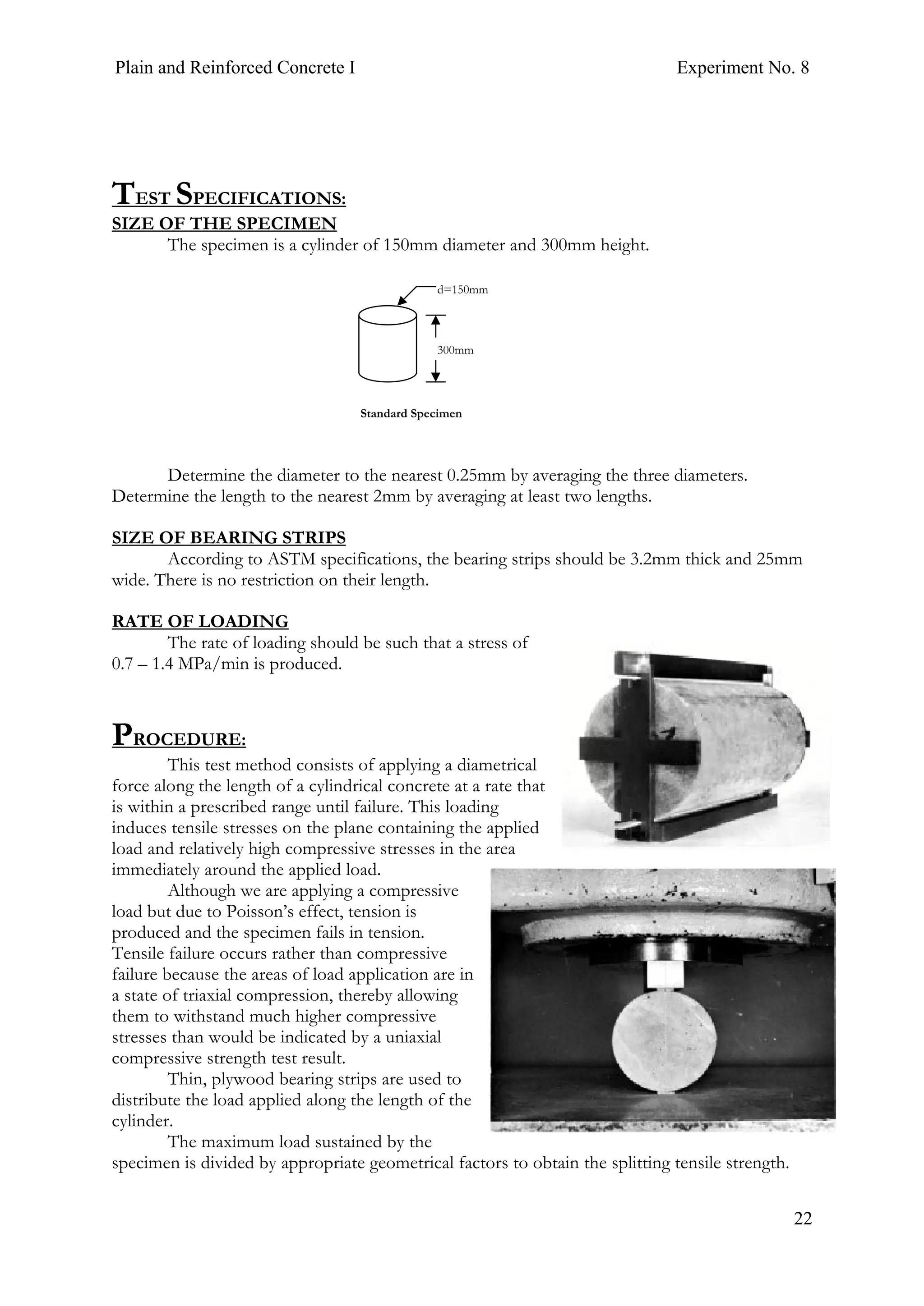
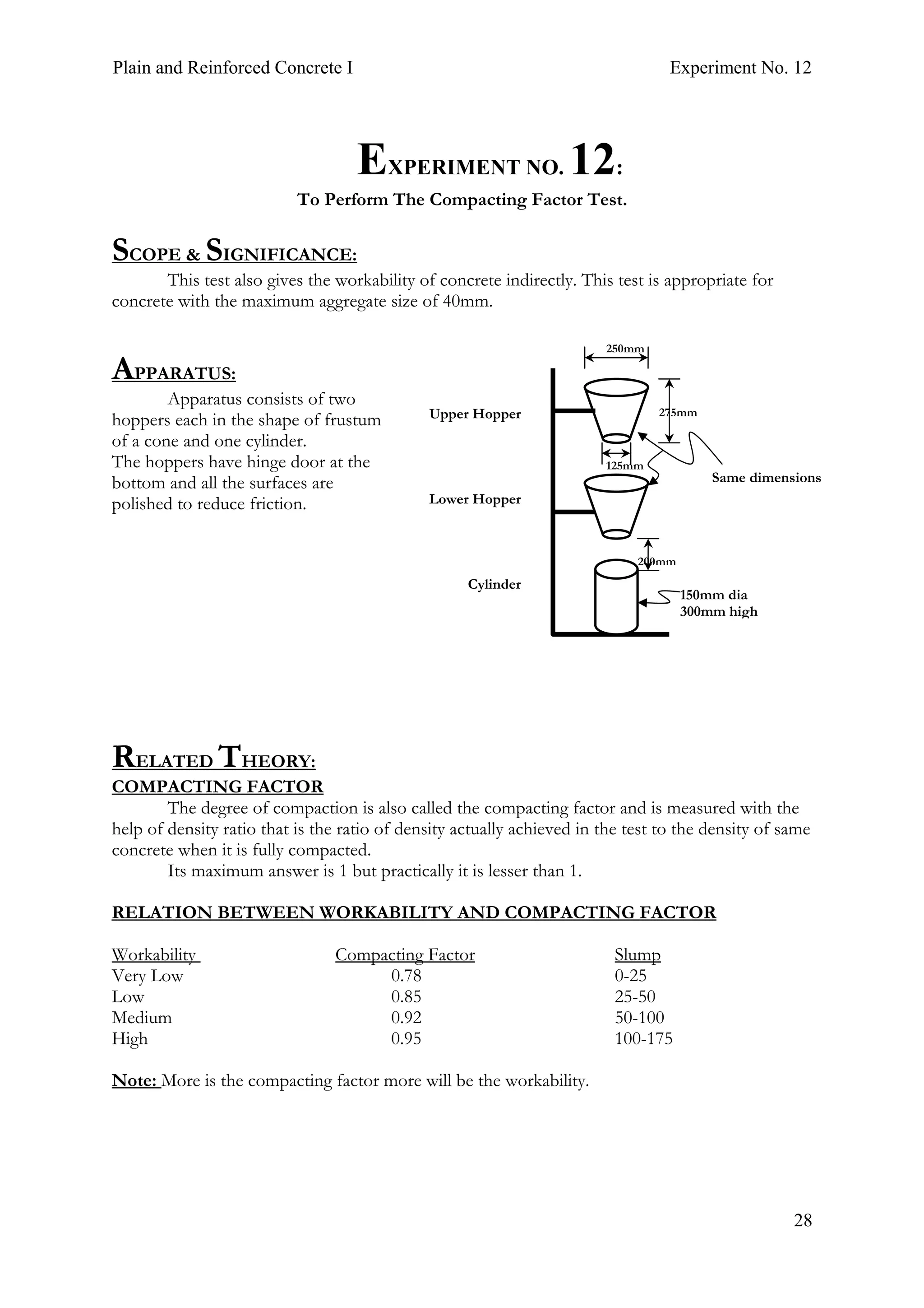
![Plain and Reinforced Concrete I Experiment No. 8
21
8. EXPERIMENT NO. 8:
Standard Test Method For The Determination Of The Splitting Tensile
Strength Of Cylindrical Concrete Specimen.
Code: ASTM C 496/C 496 M-04
SCOPE & SIGNIFICANCE:
This test method is used for the determination of splitting tensile strength of cylindrical
concrete specimen.
Splitting tensile strength is helpful for the following purposes;
1- Splitting tensile strength is generally greater than the direct tensile strength
and lower than the flexural strength (modulus of rupture).
2- Splitting tensile strength is used in the design of structural light weight
concrete members to evaluate the shear resistance provided by concrete and to
determine the development length of the reinforcement.
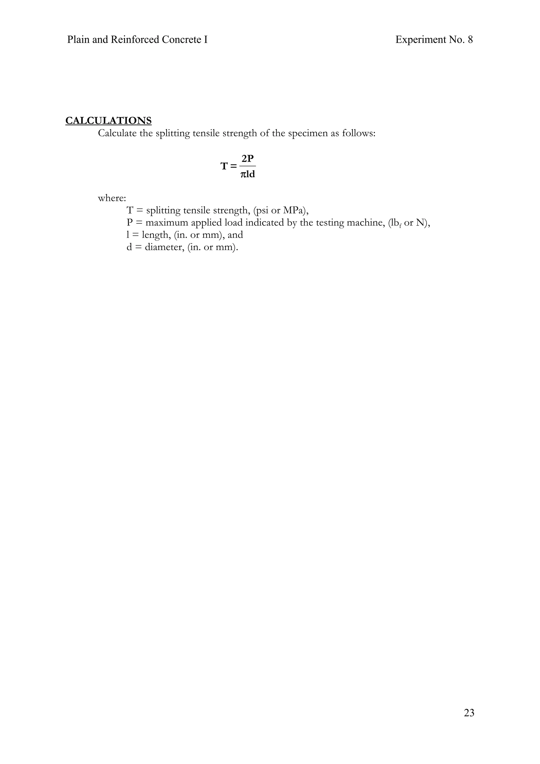
where,
T = Splitting tensile strength (to be reported in 0.05 MPa multiples)
P = Applied load
l = length of the specimen (mm)
d = Diameter of the specimen (mm)
APPARATUS:
• Testing Machine
• Supplementary Bearing Bar Or Plates (If the diameter or the largest dimension of the upper
bearing face or the lower bearing block is less than the
length of the cylinder to be tested, a supplementary bearing
bar or plate of machined steel shall be used. The bar or
plate shall be manner that the load will be applied over the
specimen.)
• Bearing Strips (Two bearing strips of nominal 1 /8 in [3.2 mm] thick
plywood, free of imperfections, approximately 1 in. [25
mm] wide, and of a length equal to, or slightly longer than,
that of the specimen shall be provided for each specimen.
The bearing strips shall be placed between the specimen
and both the upper and lower bearing blocks of the testing
machine or between the specimen and supplemental bars or
plates, when used (see 5.2). Bearing strips shall not be
reused.)
ld
P2
T
π
=](https://image.slidesharecdn.com/manualprc-1-180721012233/75/PLAIN-AND-REINFORCED-CONRETE-LAB-MANUAL-23-2048.jpg)
![Plain and Reinforced Concrete I Experiment No. 9
24
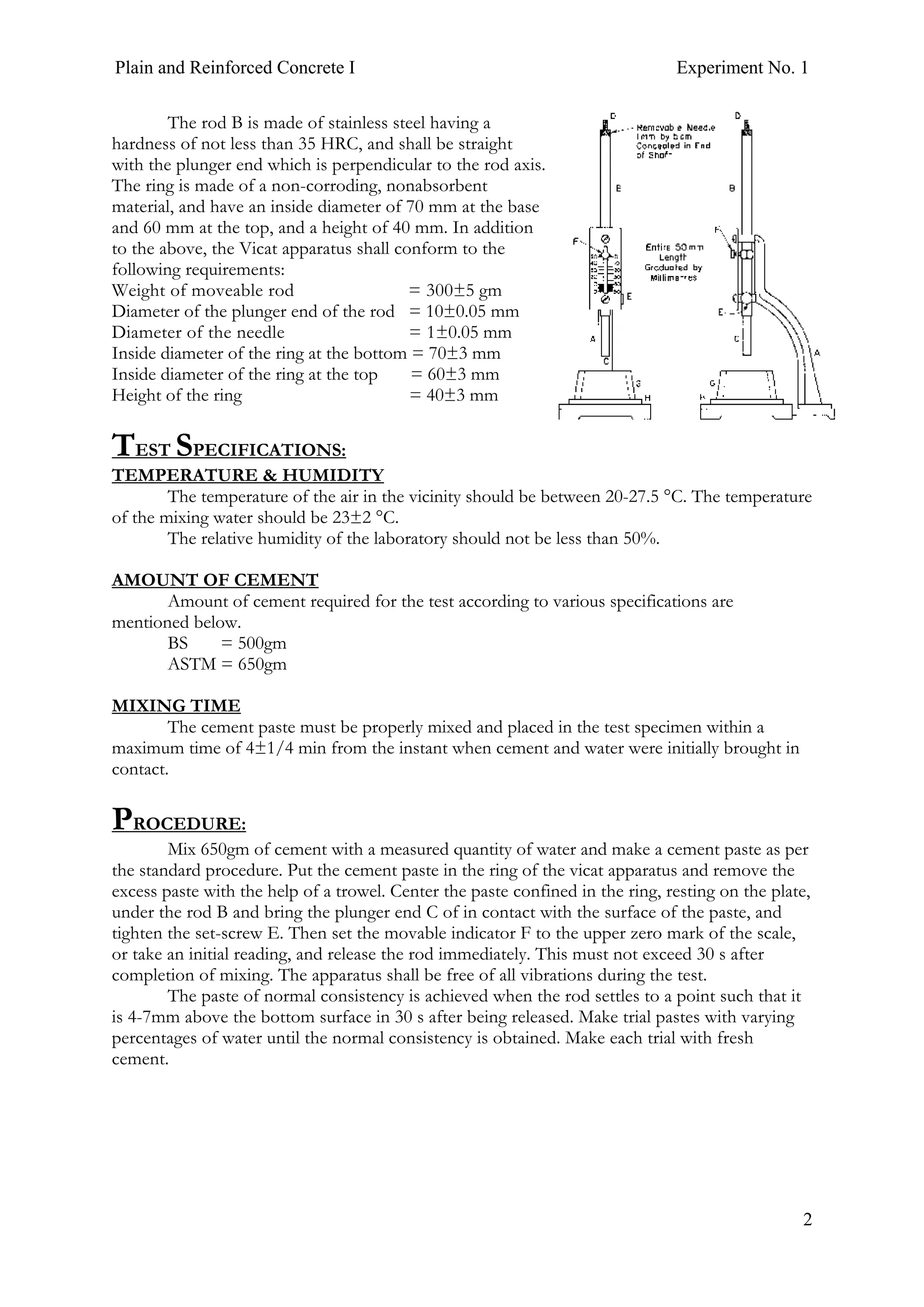
9. EXPERIMENT NO. 9:
Determination Of The Tensile Strength Of Concrete By Double Punch
Test. (Non-Standard Test)
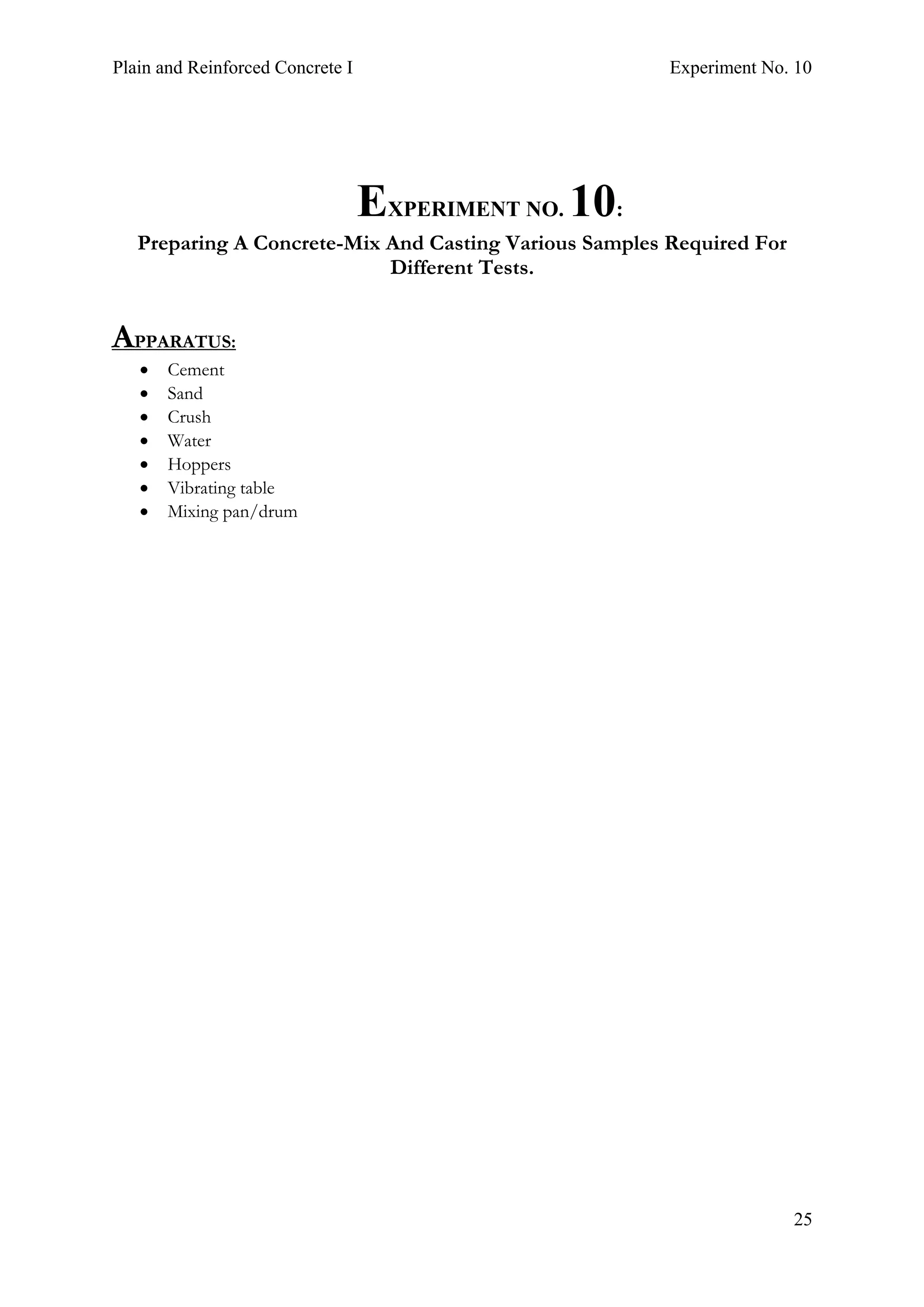
APPARATUS:
• Testing Machine
• Testing Samples
• Punches (2 in number, to be placed at the top and bottom of the sample)
TEST SPECIFICATIONS:
SIZE OF THE SPECIMEN
The specimen is a cylinder of 150mm diameter and 150mm height.
PROCEDURE:
It is an indirect method in which we determine the tensile strength
of concrete based on the theory of perfect plasticity.
In this test a concrete cylinder is placed vertically between the
loading platens of the machine and is compressed by two steel punches
placed parallel to the top and bottom end surfaces.
The sample splits across many vertical diametrical planes radiating
from central axis.
Samples should be placed under wet conditions for 24 hours and
later on in a curing tank for 28 days.
CALCULATION
The tensile strength can be computed as;
ft = Q / [Π (1.2bH - a2
)]
where,
Q = Crushing Load
H
Q
Q
2b
2a
150mm
d=150mm
Specimen](https://image.slidesharecdn.com/manualprc-1-180721012233/75/PLAIN-AND-REINFORCED-CONRETE-LAB-MANUAL-26-2048.jpg)

The document outlines various experiments related to the testing of hydraulic cement and aggregates, detailing procedures, apparatus, and specifications for tests such as determining normal consistency, setting times, and fineness modulus. Each experiment is referenced by a specific ASTM code and includes essential information about materials and environmental conditions necessary for accurate results. Key aspects include methodologies for assessing properties vital for concrete quality and performance.