Call Girls Delhi {Jodhpur} 9711199012 high profile service
Rcc lab manual
1. Experiment No 1
Preparationof a cement paste of Standard Consistency
Reference
ASTM C 187
Objective/Theory:
Consistency is a measure of wetness or fluidity of a cement.
The main purpose of the consistency test is to determine the required quantity of
water to obtain a standard or homogeneous paste ,and water quantity is enough to
hydration process
The standard consistency of a cement paste is defined as
that “consistency which will permit the vicat plunger to penetrate to a point 10 ± 1
mm below the original surface in 30 s after being released
Apparatus:
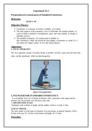
1. VICAT APPARATUS
The vicat apparatus consists of a frame having a movable rod with a cap at one end and at the
other end the attachment, which are interchangeable.
figure (vicat apparatus)
2. PLUNGER FOR STANDARD CONSISTANCY
It is of polished brass 10 ± 0.05mm in diameter with a projection at the upper end for
insertion into the movable rod. The lower end is flat.
3. GRUADUATED SCALE
Graduated scale is 40mm in length and the smallest division of scale is 1mm
4.VICAT MOULD
The vicat mould is in the foam of a frustum of a cone having an internal diameter of 60 ±
0.5mm at the top, 70 ± 0.5mm at the bottom and height 40 ± 0.5mm.
Procedure
2. 1) Mix 650 g of cement with a measured quantity of water and smooth the top, with a few
light touches of the pointed end of the trowel.
2) Quickly form the cement paste into the approximate shape of a ball with gloved hands.
3) Then toss six times through a free path of about 150 mm (6 in.) from one hand to another
so as to produce a nearly spherical mass that may be easily inserted into the Vicat ring
with a minimum amount of additional manipulation.
4) Press the ball, resting in the palm of one hand, into the larger end of the conical ring
held in the other hand, completely filling the ring with paste.
5) Remove the excess at the larger end by a single
movement of the palm of the hand.
6) Place the ring on its larger end on the base plate and slice off the excess paste at the
smaller end at the top of the ring and smooth the top.
7) During these operations of cutting and smoothing, take care not to compress the paste.
8) Center the paste confined in the ring, resting on the plate, under the rod, the plunger
end of which shall be brought in contact with the surface of the paste, and
tighten the set-screw.
9) Then set the movable indicator to the upper zero mark of the scale, or take an initial
reading, and release the rod immediately.
10) This must not exceed 30 s after completion of mixing.
11) The apparatus shall be free of all vibrations during the test.
12) The paste shall be of normal consistency when the rod settles to a point 10 ± 1 mm
below the original surface in 30 s after being released.
13) Make trial pastes with varying percentages of water until the normal consistency is
obtained. Make each trial with fresh cement.
OBSERVATIONS AND CALCULATIONS:
Weight of cement taken (g) = _________
Sr. No Weight OF WATER ADDED
(g)
Amount of water
(%)
Depth of penetration
(mm)
Standard Consistency
= (Quantity of water for 10 ± 1 penetration from Top Surface of mould /Weight of cement) X
100
Significance ofTesting:
This method is intended to be used to determine the amount of water required to
prepare hydraulic cement pastes for testing.
3. Experiment-02
Determination of Initial and Final setting time of cement.
Reference
ASTM C 191 – 04a
Objective/Theory
Setting
In the setting process very little chemical reaction takes place. It only includes the shape acquisition
due to evaporation of water.
During the setting process the cement remains in the fluid or the semi-fluid state and there is very
little or no gain in strength.
Finer the cement particles more will be the hydration and therefore it will lead to quick settlement.
Hardening
Hardening is the rate of gain of strength due to the chemical reaction.
It also refers to the strength of the concrete after a specified interval of time.
The Vicat initial time of setting is the time elapsed between the initial contact of cement
and water and the time when the penetration is measured or calculated to be 25 mm.
The Vicat final time of setting is the time elapsed between initial contact of cement and
water and the time when the needle does not leave a complete circular impression in the
paste surface.
Apparatus
1. VICAT APPARATUS
• The vicat apparatus consists of a frame having a movable rod with a cap at one end and
at the other end the attachment, which are interchangeable
Figure (Vicat Apparatus)
2. NEEDLE
• The end of the rod used for measuring penetration shall have a straight steel removable needle
with a diameter of 1.00 ± 0.05 mm and length no less than 50 mm.
3. GRUADUATED SCALE
• Graduated scale is 40mm in length and the smallest division of scale is 1mm
4. 4. VICAT MOULD
• The vicat mould is in the foam of a frustum of a cone having an internal diameter of 60 ±
0.5mm at the top, 70 ± 0.5mm at the bottom and height 40 ± 0.5mm.
5. PLANE NON-ADSORPTIVE PLATE,
• 100 ± 5 mm square of similar planeness, and absorptivity to that of glass
Procedure
1. Prepare a new batch of paste by mixing 650 g of cement with the percentage of mixing
water required for normal consistency
2. Quickly form the cement paste into a ball with gloved hands and toss six times from one
hand to the other, maintaining the hands about 150 mm (6 in.) apart.
3. Press the ball, resting in the palm of the hand, into the larger end of the conical ring, held
in the other hand, completely filling the ring with paste.
4. Remove the excess at the larger end by a single movement of the palm of the hand.
5. Place the ring on its larger end onto the no absorptive plate and slice off the excess paste at
the smaller end at the top of the ring by a single oblique stroke of the trowel held at a slight
angle with the top of the ring
6. Smooth the top of the specimen, if necessary, with one or two light touches of the pointed
end of the trowel. During the operation of cutting and smoothing, take care not to compress
the paste.
7. Immediately after molding, place the test specimen in the moist cabinet or moist room and
allow it to remain there except when penetration measurements are being made.
8. The specimen shall remain in the conical mold, supported by the non-absorptive plate
throughout the test period.
9. Allow the time of setting specimen to remain in the moist cabinet or moist room for 30 min
after molding without being disturbed.
10. Determine the penetration of the 1-mm needle at this time and every 15 min thereafter
until a penetration of 25 mm or less is obtained.
11. Perform the penetration test by lowering the needle of the rod until it rests on the surface
of the cement paste. T
12. Tighten the setscrew and set the indicator at the upper end of the scale, or take an initial
reading.
13. Release the rod quickly by releasing the set screw and allow the needle to settle for 30 s;
then take the reading to determine the penetration.
14. Make each penetration test at least 5 mm away from any previous penetration and at least
10 mm away from the inner side of the mold.
15. Record the results of all penetration tests and, by interpolation, determine the time when a
penetration of 25 mm is obtained.
16. The elapsed time between the initial contact of cement and water and the penetration of
25 mm is the Vicat time of setting or Vicat initial time of setting.
17. Determine the Vicat final time of setting end point to be the first penetration measurement
that does not mark the specimen surface with a complete circular impression.
18. Verify final set by performing two additional penetration measurements on different areas
of the specimen surface.
19. Obtain verification measurements within 90 s of the first “final set” measurement.
5. The elapsed time between the initial contact of cement and water and the end point
determination above is the Vicat final time of setting.
OBSERVATIONSAND CALCULATIONS
Calculate the Vicat Initial time of setting to the nearest 1 min as follows:
((H-E/C-D)x(C-25))+E
where:
E =Time in minutes of last penetration greater than 25 mm,
H =Time in minutes of first penetration less than 25 mm,
C = Penetration reading at time E.
D = Penetration reading at time H.
Calculate the Vicat final time of setting by determining the elapsed time between the
time of the initial contact between cement and water and the time when the needle does
not sink visibly into the paste, rounded to the nearest 5 min.
O Vicat initial time of setting ______ min
O Vicat final time of setting ______ min
Initial setting time
Time of setting, min, not
less
than
45
Final setting time
Time of setting, min, not
more
than
375
Significance ofTesting
The knowledge of the setting time of the cement is always helpful in deciding the
time duration to mix, transport, place and compact the concrete effectively
6. EXPERIMENT NO 3
SLUMP TEST OF CONCRETE
Reference C143
CONCRETE SLUMP TEST:
The concrete slump test is an empirical test that measures the workability of fresh concrete.
The test is performed to check the consistency of freshly mixed concrete in a specific batch.
Consistency refers to the ease and homogeneity with which the concrete can be mixed,
placed, compacted and finished. This test is most widely used due to the simplicity of
apparatus and simple test procedure.
Slump Test
The slump test gives satisfactory results for the concrete mix of medium to high workability
and unfortunately, it does not give the correct indication of low workability, which may give
zero slumps. This test is also known as slump cone test.
Gap-gradedAggregate. ... Aggregate containing particles
of both large and small sizes, in which particles of certain
intermediate sizes are wholly or substantially absent.
well-gradedaggregate:
A slice of a core of well-graded aggregate concrete shows a packed
field of many different particle sizes. It is characterized by the S-
shaped in gradation curve.
7. • Poor graded : Poor-graded aggregate is characterized by small variation in size. It
containsaggregate particles that are almost of the same size.
Uniformly Graded Aggregate:
For uniformly graded aggregate, only a few sizes dominate the bulk material. With this
grading, the aggregates are not are not effectively packed, and the resulting concrete will be
more porous, unless a lot of paste is employed.
APPARATUS FOR CONCRETE SLUMP TEST:
1. Mould or slump cone with a height of 300 mm, bottom
diameter 200 mm, and top diameter 100 mm.
2. Standard tamping rod.
3. Non-porous base plate.
4. Measuring scale.
PROCEDUREOF TEST:
1. First, clean the inner surface of the empty mould and then apply oil to it.
2. Set the mould on a horizontal non-porous and non-absorbent base plate.
3. Fill the mould fully by pouring freshly mixed concrete in three equal layers.
4. Stroke each layer 25 times with the standard tamping rod over the cross section.
5. After stroking 25 times the top layer is struck off level, now lift the mould slowly in the
vertical direction without disturbing the concrete cone.
8. 6. Use the measuring scale to measure the difference level between the height of the mould
and the concrete sample.
The subsidence of concrete is known as the slump and the value of slump is measured in mm.
TYPES OF SLUMP:
True Slump: The concrete mass after the test when slumps evenly all around without
disintegration is called the true slump.
Shear Slump: When one-half of the concrete mass slide down the other is called the
shear slump. This type of slump is obtained in a lean concrete mix.
Collapse Slump: When the sample is collapsed due to adding excessive water, it is
known as collapse slump.
Zero Slump: For very stiff or dry mixes it does not show any changes of the slump
after removing the slump cone.
9. ADVANTAGES OF CONCRETE SLUMP TEST:
1. The procedure of slump test is simple and easy than any other workability test.
2. Inexpensive and portable apparatus are required for this test.
3. Slump test can be performed at the construction site as well as in the laboratory.
LIMITATIONS OF CONCRETE SLUMP TEST:
1. The slump test is limited to concretes with the maximum size of aggregate less than 38
mm.
2. The test is suitable only for concretes of medium or high workabilities (i.e having slump
values of 25 mm to 125 mm).
3. For very stiff mixes having zero slumps, the slump test does not show any difference in
concretes of different workabilities.
RecommendedValues Of Slumps For Different Concrete Mixes:
Types Of Concrete
Slump Range In
mm
1. Heavy mass construction 25-50
2. Pavements 20-30
3. Bridge deck 25-75
4. Beams and slabs 50-100
5. Columns, retaining walls
and thin vertical members etc.
75-150
6. Vibrated concrete 12-25
10. EXPERIMENT NO 4
Sieve Analysis Of Coarse Aggregate
Reference:
ASTM C 136-05
Objective/Theory
It is the operation of dividing the aggregate into various fractions, each consisting of
particles of same size.
This test method covers the determination of the particle size distribution of coarse
aggregates by sieving.
A sample of dry aggregate of known mass is separated through a series of sieves of
progressively smaller openings for determination of particle size distribution.
Sieve No. 4 is the dividing line between coarse and fine aggregate.
Apparatus
Balances.
Sieves for coarse aggregates.
Mechanical Sieve Shaker.
Drying Oven.
Procedure:
1) The size of the test sample of coarse aggregate shall conform with the following:
11. 2) Dry the sample to constant mass at a temperature of 110 ± 5 °C (230 ± 9 °F).
3) Nest the sieves in order of decreasing size of opening from top to bottom and place
the sample on the top sieve
4) Agitate the sieves by hand or by mechanical apparatus for a sufficient period.
5) Determine the mass of each size increment on balance and record to the nearest 0.1%
of the total original dry sample mass.
6) Total mass of material after sieving should not differ by more than 0.3% of the
original dry sample after completion of sieving procedure if greater than 0.3%, the
results should not be used for acceptance purposes.
Sieve
No.
Sieve
size(mm)
3" 76.2
5/2”
63.5
2” 50.8
3/2" 38.1
1” 25
3/4" 19
1/2" 12.5
3/8" 9.5
3/16" 4.75
Pan 0
OBSERVATIONSAND CALCULATIONS:
Significance ofTesting
This test method is used primarily to determine the grading of materials proposed
for use as aggregates or being used as aggregates.
The results are used to determine compliance of the particle size distribution with
applicable specification requirements and to provide necessary data for control of
the production of various aggregate products and mixtures containing aggregates.
Sr
No.
Sieve
No.
Sieve
size(m
m)
Wt of
empty
sieve(g)
Wt. of sieve
+aggregate(
g)
Wt.
retained
(g)
(Col.5-
Col.4)
Percentage
Wt.
retained(%)
(Col.6/Total
wt. x100)
Cumulative
wt.
retained(g)
Cumulative
percentage wt.
retained(%)
(Col.8/Total wt.
x100)
Percentage
finer(%)
(100-Col.9)
1 3" 76.2
2
5/2”
63.5
3 2” 50.8
4 3/2" 38.1
5 1” 25
6 3/4" 19
7 1/2" 12.5
8 3/8" 9.5
9 3/16" 4.75
10 Pan 0