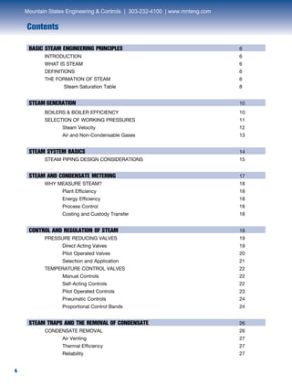
Controls and regula- tors for ideal temperature, pressure and flow control; steam traps for efficient drainage of condensate for maximum heat transfer; flowmeters for precise mea- surement of liquids; liquid drain traps for automatic and continuous drain trap operation to boost system efficiency; rotary filters for increased productivity through proper filtering of fluids; condensate recovery pumps for effective condensate management to save water and sewage costs; stainless steel specialty products for maintaining quality and purity of steam; and a full range of pipeline auxiliaries, all work together to produce a productive steam system. Spirax Sarco’s new line of engineered equipment reduces installation costs with prefabricated assemblies and fabricated modules for system integrity and turnkey advantages.
This presentation describes the considerations involved in selecting the shell and tube exchanger according to TEMA Designations. Also, it helps to identify whether fluid should be sent tube side or shell side
Design of Sprinkler System and CO2 Total Flooding System of Given Plan I Gaur...Gaurav Singh Rajput
This project includes two parts
1. Sprinkler System Design
2. CO2 Total Flooding System Design
In sprinkler system design first given plan were studied and its area divided on the basic of hazardous classification of building as per NBC Part- 4 and number of sprinklers required in area were calculated. Then pressure and flow rate of water at externa inlet valve were calculated. Number of hangers, range pipe and distribution pipes were calculated.
In CO2 Total Flooding System Design number of co2 cylinder required for the given compartment for total flooding system were calculated.
Gaurav Singh Rajput I gauravsinghrajput I gauravkrsrajput
AIChE Smart Stack Damper Design Provides Better Control of Fired HeatersAshutosh Garg
Stack dampers are one of the insignificant yet important component of fired heaters in the refining industry. Over 90% of the heaters in the USA are natural draft and are dependent upon the draft for efficient combustion of fuel gas with air. Stack dampers currently installed are highly oversized and are not able to control draft effectively. Furnace Improvements patent pending design overcomes these limitations and improves the damper control significantly by installing multiple actuators and changing the control characteristics of the dampers.
Water steam Circuit in Supercritical Boiler for 660MW Power PlantHareesh VS
An animated presentation over Complete water steam circulation in a super critical boiler with flow chart. The water-steam path through various Systems (High pressure & Low pressure systems) in boiler for a 660MW thermal power plat, and also indicates the temperature and pressure variations after flowing through individual systems. Watch Live Presentation on YouTube: http://youtu.be/snIVrTmI4bM
Centrifugal Compressors
SECTION ONE - ANTI-SURGE PROTECTION AND THROUGHPUT REGULATION
0 INTRODUCTION
1 SCOPE
2 MACHINE CHARACTERISTICS
2.1 Characteristics of a Single Compressor Stage
2.2 Characteristic of a Multiple Stage Having More
Than One Impeller
2.3 Use of Compressor Characteristics in Throughput
Regulation Schemes
3 MECHANISM AND EFFECTS OF SURGE
3.1 Basic Flow Instabilities
3.2 Occurrence of Surge
3.3 Intensity of Surge
3.4 Effects of Surge
3.5 Avoidance of Surge
3.6 Recovery from Surge
4 CONTROL SCHEMES INCLUDING SURGE PROTECTION
4.1 Output Control
4.2 Surge Protection
4.3 Surge Detection and Recovery
5 DYNAMIC CONSIDERATIONS
5.1 Interaction
5.2 Speed of Response of Antisurge Control System
6 SYSTEM EQUIPMENT SPECIFICATIONS
6.1 The Antisurge Control Valve
6.2 Non-return Valve
6.3 Pressure and flow measurement
6.4 Signal transmission
6.5 Controllers
7 TESTING
7.1 Determination of the Surge Line
7.2 Records
8 INLET GUIDE VANE UNITS
8.1 Application
8.2 Effect on Power Consumption of the Compressor
8.3 Effect of Gas Conditions, Properties and Contaminants
8.4 Aerodynamic Considerations
8.5 Control System Linearity
8.6 Actuator Specification
8.7 Avoidance of Surge
8.8 Features of Link Mechanisms
8.9 Limit Stops and Shear Links
APPENDICES
A LIST OF SYMBOLS AND PREFERRED UNITS
B WORKED EXAMPLE 1 COMPRESSOR WITH VARIABLE INLET PRESSURE AND VARIABLE GAS COMPOSITION
C WORKED EXAMPLE 2 A CONSTANT SPEED ~ STAGE COMPRESSOR WITH INTER-COOLING
D WORKED EXAMPLE 3 DYNAMIC RESPONSE OF THE ANTISURGE PROTECTION SYSTEM FOR A SERVICE AIR COMPRESSOR RUNNING AT CONSTANT SPEED
E EXAMPLE OF INLET GUIDE VANE REGULATION
FIGURES
2.1 TYPICAL COMPRESSOR STAGE CHARACTERISTIC PLOTTED WITH FLOW AT DISCHARGE CONDITIONS
2.2 TYPICAL COMPRESSOR STAGE CHARACTERISTIC PLOTTED WITH FLOW AT INLET CONDITIONS
2.3 PERFORMANCE CHARACTERISTICS OF A COMPRESSOR STAGE AT VARYING SPEEDS
2.4 SYSTEM WORKING POINT DEFINED BY INTERSECTION OF PROCESS AND COMPRESSOR CHARACTERISTICS
2.5 DISCHARGE THROTTLE REGULATION
2.6 BYPASS REGULATION
2.7 INLET THROTTLE REGULATION
2.8 INLET GUIDE VANE REGULATION
2.9 VARIABLE SPEED REGULATION
3.1 GAS PULSATION LEVELS FOR A CENTRIFUGAL COMPRESSOR
3.2 REPRESENTATION OF CYCLIC FLOW DURING SURGE OF LONG PERIOD
3.3 TYPICAL WAVEFORM OF DISCHARGE PRESSURE DURING SURGE
3.4 MULTIPLE SURGE LINE FOR A MULTISTAGE CENTRIFUGAL COMPRESSOR
3.5 TYPICAL MULTIPLE SURGE LINES FOR SINGLE STAGE AXIAL-FLOW COMPRESSOR
4.1 GENERAL SCHEMATIC FOR COMPRESSORS OPERATING IN PARALLEL TO FEED MULTIPLE USER PLANTS
4.2 ILLUSTRATION OF SAFETY MARGIN BETWEEN SURGE POINT AND SURGE PROTECTION POINT AT WHICH ANTISURGE SYSTEM IS ACTIVATED
4.3 ANTISURGE SYSTEM FOR COMPRESSOR WITH FLAT PERFO ..........
Steam ejector working principle
An ejector is a device used to suck the gas or vapour from the desired vessel or system. An ejector is similar to an of vacuum pump or compressor. The major difference between the ejector and the vacuum pump or compressor is it had no moving parts. Hence it is relatively low-cost and easy to operate and maintenance free equipment.
Here's a presentation on piping engineering in PDF format, now available for all. This presentation covers the basics points of piping for our EPC industry. This presentation covers various aspects of piping engineering
Within industry, piping is a system of pipes used to convey fluids (liquids and gases) from one location to another. The engineering discipline of piping design studies the efficient transport of fluid
Industrial process piping (and accompanying in-line components) can be manufactured from wood, fiberglass, glass, steel, aluminum, plastic, copper, and concrete. The in-line components, known as fittings, valves, and other devices, typically sense and control the pressure, flow rate and temperature of the transmitted fluid, and usually are included in the field of Piping Design (or Piping Engineering). Piping systems are documented in piping and instrumentation diagrams (P&IDs). If necessary, pipes can be cleaned by the tube cleaning process.
"Piping" sometimes refers to Piping Design, the detailed specification of the physical piping layout within a process plant or commercial building. In earlier days, this was sometimes called Drafting, Technical drawing, Engineering Drawing, and Design but is today commonly performed by Designers who have learned to use automated Computer Aided Drawing / Computer Aided Design (CAD) software
Air Cooled Heat Exchanger Design
0 INTRODUCTION/PURPOSE
1 SCOPE
2 FIELD OF APPLICATION
3 DEFINITIONS
4 SUITABILITY FOR AIR COOLING
4.1 Options Available For Cooling
4.2 Choice of Cooling System
5 SPECIFICATION OF AN AIR COOLED HEAT
EXCHANGER
5.1 Description and Terminology
5.2 General
5.3 Thermal Duty and Design Margins
5.4 Process Pressure Drop
5.5 Design Ambient Conditions
5.6 Process Physical Properties
5.7 Mechanical Design Constraints
5.8 Arrangement
5.9 Air Side Fouling
5.10 Economic Factors in Design
6 CONTROL
7 PRESSURE RELIEF
8 ASSESSMENT OF OFFERS
8.1 General
8.2 Manual Checking Of Designs
8.3 Computer Assessment
8.4 Bid Comparison
9 FOULING AND CORROSION
9.1 Fouling
9.2 Corrosion
10 OPERATION AND MAINTENANCE
10.1 Performance Testing
10.2 Air-Side Cleaning
10.3 Mechanical Maintenance
10.4 Tube side Access
11 REFERENCES
The COP of the refrigeration increasing the performance and to get high efficiency of the refrigeration system. By using nano coating over the evaporator of the refrigeration component the objective can be achieved. The improper heat dissipation occurred in the heat exchanger components causes effect in performance. The vapour compression refrigeration system consuming the high power. Though the energy taken for the refrigeration process has increased and leads to more power consumption. In order to increase the performance, Nano coating Copper Oxide has been applied over the evaporator. By applying the Nano coating Copper Oxide over the evaporator the COP increased. In result the energy required for the refrigeration process and global warming problems has been reduced. By addition of nanoparticles to the refrigeration results in improvements in the COP of the refrigeration, thereby improving the performance of the refrigeration system. In this experiment the effect of using CuO-R134a in the vapour compression system expected COP will be increased by 5% with nano coating.
EXPERIMENTAL INVESTIGATION OF WASTE HEAT RECOVERY SYSTEM FOR DOMESTIC REFRIGE...IAEME Publication
The objective of this project was to determine the energy savings associated with improved utilization of waste heat from a domestic refrigerator. Domestic refrigerators maybe operate
continuously to maintain proper food storage condition. The continual operation of this equipment accounts more electrical energy consumption. Furthermore, a significant amount of waste heat is rejected by the condensers of refrigerator.
HRSFUNKE Heat Transfer Group operates at the forefront of thermal processing technology and is a leading heat transfer specialist. The company provides high quality and effective heat transfer solutions across a broad spectrum of industries. Industries supplied include marine, food and beverages, sugar, oil and gas, petrochemical and chemical, pharmaceu-ticals, power, HVAC / district cooling, refrigeration, domestic hot water heating and steam systems.
Flue gas low temperature heat recovery system for air conditioningeSAT Journals
Abstract Huge amount of energy wasted through the flue gas in thermal power station causes great concern in recent years. Discharging hot flue gas in the environment is not only a wastage of energy but also increases the rate of global warming. Efforts are given world -wide to harness the energy for useful purposes. In this work, the waste heat of flue gas in a 350 MW thermal power plant is utilized in vapor absorption air conditioning plant. Gas to liquid multi-pass cross flow heat exchanger that have been placed in the existing space between boiler and chimney. The dimensions of the finally selected heat exchanger are 0.106m × 2.4m × 3.4m. The number of pipes required for the heat exchanger is found to be 12 using iteration method and temperature of water at the outlet of last pipe is 101.1℃. The extracted energy from the flue gas is used to heat water to be utilized in the generator of a vapor absorption refrigeration system that has produced a refrigerating capacity of 70 TR. approximately. Due to the corrosive nature of flue gas, heat recovery is confined up to the acid dew point temperature of the flue gas. Suitable software is used to find out the detailed design parameters of Gas to liquid multi-pass cross flow heat exchangers. Out of many feasible designs of heat exchangers, the most economic design is selected as the final design. Keywords—Air Conditioning; Flue Gas; Heat Exchanger; Heat Recovery; Vapour Absorption Machine
Thermo Tech Engineering (TTE) is involved in manufacturing of industrial utility equipments and general fabrication. We offer complete waste heat recovery equipment Custom design fabrication installation and commissioning.
Mining applications can be hard on the equipment. Abrasive, corrosive, erosive — all those conditions apply in varying proportions. So it can come as a relief to know that FluoroSeal® Non-Lubricated Plug Valves, both Sleeved and Lined, can handle even the hardest of condition combinations, in a variety of mining operations.
Roth regenerative turbine chemical duty pumps provide continuous, high pressure pumping of non-lubricating and corrosive liquids. These regenerative turbine pumps are provided with one piece, machined self-centering impellers for operation with a wide variety of chemicals .
Custom Control Sensors, Inc. (CCS) is a global leader in the design,
testing, manufacturing and supply of pressure, temperature and liquid
flow switches for the Industrial, Energy, Aerospace and Defense markets.
Founded in 1958, CCS revolutionized the industrial pressure switch
market by utilizing its patented Dual-Snap® disc spring technology.
Spirax Sarco, leader in products and services for steam system management, released the PV4 and PV6 piston valves for isolation purposes. The valves are available in NPT and SW versions, from ½” to 2”. Bodies are available in forged carbon steel or forged stainless steel.
These valves are designed to Class 800 and provide tight shutoff, suitable for steam, condensate and other liquid systems.
KING-GAGE® Systems are designed and manufactured by King Engineering as application specific solutions for level measurement and inventory tank gauging. Our company furnishes components for new installations, upgrades, and retrofit applications on storage or processing vessels, including electronic pressure transmitters and sanitary level sensors to meet 3-A standards for clean-in-place applications. We provide graphic tank level indicators, digital processors, and operator interfaces in both single and multiple tank configurations supporting industrial protocols for PLC and/or LAN interfaces to simplify process control integration.
Roth Pump standard steam condensate pump stations are the most popular and meet most water applications. These units will deliver hot water at temperatures up to 200˚F (93˚C) and will not vapor bind at 210˚F (98˚C). Receiver capacities from 8 (30 liters) to 50 gallons (189 liters) can be supplied on these standard condensate pump units.
Eliminate cavitation at high temperatures. Manage a higher load during cold starts. Dependable pumps to handle hotter water. Higher pressure at lower motor speeds. No mechanical seals below water line.
Pneumatic Products BAP desiccant dryer purifiers are designed to provide a continuous supply of clean, safe breathing air from your existing compressed air system.
The ISV product line includes valve sizes ranging form 1/4" to 56" in pressure classes through 2500 and up to 10,000 psig working pressures with a large selection of body materials and trims.
Pipeline, Oil & Gas Service Ball Valves
API 6D and API 608, API 607 Firesafe with NACE compliance
2 & 3 piece trunion mounted ball valves
2 & 3 piece floating ball valves
Industrial Floating Ball Valves
API 608 / ASME B16.34, API 607 Firesafe with NACE compliance
2 & 3 piece flanged, SW, BW and NPT
Uni-body NPT
2 & 3 piece NPT industrial valves
Spirax Sarco provides knowledge, service, products and turnkey solutions for the control and efficient use of steam, air and other industrial fluids for industrial and commercial users.
Steam Traps - All types and sizes including repair kits
Regulators - Pressure, temperature, back pressure and relief
Condensate - Pumps Electric and steam driven
Control Systems - Valves and actuators
Steam thermocompressors utilize a flow of high pressure steam to boost the pressure of a stream of low pressure steam. The purpose can be to either recycle the low pressure steam with the added heat, or to create a usable steam supply from a low pressure steam source.
Monitrol is a turn-key fluid control system including a globe style control valve, a variety of built in sensors for Flow, Pressure and Temperature, a High Precision Electric Actuator, along with controller and an easy to use Touch Screen interface. Monitrol can manage up to three variables (sensors), simultaneously with its control logic. Flexibility allows the control logic in Monitrol to be bypassed if that is desired. A Building Management System can still maintain all control and just make use of the sensor information if that is desired. A full range of I/O signals, feedback and modbus TCP communications are standard.
Hytork® develops and manufacturers actuators for the automation of industrial valves. Product range includes pneumatic actuators and a wide range of control accessories. Product development is based on modular construction that allows for fast delivery from stock components and easy upgrade to control units as well as quick and efficient modification and repair.
SPX Flow, under the Pneumatic Products brand, manufactures single and twin tower desiccant dryers designed to remove water vapor from natural gas. The skid mounted units also include particulate and coalescing filters that capture solid contaminants to a submicron level.
The Spirax Sarco Direct Operated Temperature Regulators are for use on steam and liquid applications. The regulators give stable, modulating control within close tolerances. On storage and constant load applications they will control at set value. On variable load applications they will normally operate within
a very narrow temperature band.
Hytork® develops and manufacturers actuators for the automation of industrial valves. The product range includes pneumatic actuators and a wide range of control accessories. Product development is based on modular construction that allows for fast delivery from stock components and easy upgrade to control units as well as quick and efficient modification and repair.
For closed-circuit cooling, Delta recommends a cooling tower plus a plate heat exchanger system. The skid-mounted plate heat exchanger provides a closed-circuit on the hot side of the heat exchanger. The non-corroding Delta cooling tower feeds the cold side of the plate heat exchanger.
Three piece body valves area multi-purpose ball valves. They tend to be used in more demanding applications where maintenance will be required on a more frequent basis than 2 piece valves. The 3 piece body's center section can be removed to allow the valve end caps to be welded without the possibility of damaging the valve seats. Any combination of end connections can be supplied to meet your custom requirements.
Historically electric actuators had never been deemed 'capable' in industrial applications. Not capable as they could not take the ambient temperatures of those application environments, they did not have the speed, they were not 'robust', they did not have the Fail-Safe capability, or if they did have all these attributes the cost was prohibitive. The ILEA series of industrial linear electric actuators overcomes previous weaknesses in electric valve actuators.
Because of their structural design, trunnion mount ball valves are suitable for all pressure ranges and sizes.They are used by many manufacturers as a basis of design for their severe service ball valve offerings. A trunnion mount ball valve can also be advantageous for applications employing valve automation. Since the ball is not held in place by a tight fitting seal arrangement, operating torque tends to be lower for comparably sized trunnion valves, when compared to floating ball valves.
Ball valves are used throughout fluid based applications, from residential to heavy industrial. The compact and rugged design of this valve type provides superior service when properly applied. There are many variants of the basic design, with manufacturers providing builds that meet very specific and stringent requirements posed by certain types of industrial process control applications.
More from Mountain States Engineering and Controls (20)
Welcome to WIPAC Monthly the magazine brought to you by the LinkedIn Group Water Industry Process Automation & Control.
In this month's edition, along with this month's industry news to celebrate the 13 years since the group was created we have articles including
A case study of the used of Advanced Process Control at the Wastewater Treatment works at Lleida in Spain
A look back on an article on smart wastewater networks in order to see how the industry has measured up in the interim around the adoption of Digital Transformation in the Water Industry.
Student information management system project report ii.pdfKamal Acharya
Our project explains about the student management. This project mainly explains the various actions related to student details. This project shows some ease in adding, editing and deleting the student details. It also provides a less time consuming process for viewing, adding, editing and deleting the marks of the students.
Final project report on grocery store management system..pdfKamal Acharya
In today’s fast-changing business environment, it’s extremely important to be able to respond to client needs in the most effective and timely manner. If your customers wish to see your business online and have instant access to your products or services.
Online Grocery Store is an e-commerce website, which retails various grocery products. This project allows viewing various products available enables registered users to purchase desired products instantly using Paytm, UPI payment processor (Instant Pay) and also can place order by using Cash on Delivery (Pay Later) option. This project provides an easy access to Administrators and Managers to view orders placed using Pay Later and Instant Pay options.
In order to develop an e-commerce website, a number of Technologies must be studied and understood. These include multi-tiered architecture, server and client-side scripting techniques, implementation technologies, programming language (such as PHP, HTML, CSS, JavaScript) and MySQL relational databases. This is a project with the objective to develop a basic website where a consumer is provided with a shopping cart website and also to know about the technologies used to develop such a website.
This document will discuss each of the underlying technologies to create and implement an e- commerce website.
Industrial Training at Shahjalal Fertilizer Company Limited (SFCL)MdTanvirMahtab2
This presentation is about the working procedure of Shahjalal Fertilizer Company Limited (SFCL). A Govt. owned Company of Bangladesh Chemical Industries Corporation under Ministry of Industries.
Overview of the fundamental roles in Hydropower generation and the components involved in wider Electrical Engineering.
This paper presents the design and construction of hydroelectric dams from the hydrologist’s survey of the valley before construction, all aspects and involved disciplines, fluid dynamics, structural engineering, generation and mains frequency regulation to the very transmission of power through the network in the United Kingdom.
Author: Robbie Edward Sayers
Collaborators and co editors: Charlie Sims and Connor Healey.
(C) 2024 Robbie E. Sayers
3. 33
Spirax Sarco
Spirax Sarco is the recognized industry standard
for knowledge and products and for over 100 years
has been committed to servicing the steam users
worldwide. The existing and potential applications for
steam, water and air are virtually unlimited. Beginning
with steam generation, through distribution and uti-
lization and ultimately returning condensate to the
boiler, Spirax Sarco has the solutions to optimize
steam system performance and increase productivity
to save valuable time and money.
In today’s economy, corporations are looking for reli-
able products and services to expedite processes and
alleviate workers of problems which may arise with
their steam systems. As support to industries around
the globe, Spirax Sarco offers decades of experience,
knowledge, and expert advice to steam users world-
wide on the proper control and conditioning of steam
systems.
Spirax Sarco draws upon its worldwide resources of
over 4000 people to bring complete and thorough
service to steam users. This service is built into our
products as a performance guarantee. From initial
consultation to effective solutions, our goal is to
manufacture safe, reliable products that improve
productivity. With a quick, responsive team of sales
engineers and a dedicated network of local authorized
distributors Spirax Sarco provides quality service and
support with fast, efficient delivery.
Reliable steam system components are at the heart
of Spirax Sarco’s commitment. Controls and regula-
tors for ideal temperature, pressure and flow control;
steam traps for efficient drainage of condensate for
maximum heat transfer; flowmeters for precise mea-
surement of liquids; liquid drain traps for automatic
and continuous drain trap operation to boost system
efficiency; rotary filters for increased productivity
through proper filtering of fluids; condensate recovery
pumps for effective condensate management to save
water and sewage costs; stainless steel specialty
products for maintaining quality and purity of steam;
and a full range of pipeline auxiliaries, all work together
to produce a productive steam system. Spirax Sarco’s
new line of engineered equipment reduces installation
costs with prefabricated assemblies and fabricated
modules for system integrity and turnkey advantages.
From large oil refineries and chemical plants to local
laundries, from horticulture to shipping, for hospitals,
universities, offices and hotels, in business and gov-
ernment, wherever steam, hot water and compressed
air is generated and handled effectively and efficiently,
Spirax Sarco is there with knowledge and experience.
For assistance with the installation or operation of any
Spirax Sarco product or application, call toll free:
1-800-883-4411
Mountain States Engineering & Controls | 303-232-4100 | www.mnteng.com
4. 4
Contents
4
BASIC STEAM ENGINEERING PRINCIPLES 6
INTRODUCTION 6
WHAT IS STEAM 6
DEFINITIONS 6
THE FORMATION OF STEAM 6
Steam Saturation Table 8
STEAM GENERATION 10
BOILERS & BOILER EFFICIENCY 10
SELECTION OF WORKING PRESSURES 11
Steam Velocity 12
Air and Non-Condensable Gases 13
STEAM SYSTEM BASICS 14
STEAM PIPING DESIGN CONSIDERATIONS 15
STEAM AND CONDENSATE METERING 17
WHY MEASURE STEAM? 18
Plant Efficiency 18
Energy Efficiency 18
Process Control 18
Costing and Custody Transfer 18
CONTROL AND REGULATION OF STEAM 19
PRESSURE REDUCING VALVES 19
Direct Acting Valves 19
Pilot Operated Valves 20
Selection and Application 21
TEMPERATURE CONTROL VALVES 22
Manual Controls 22
Self-Acting Controls 22
Pilot Operated Controls 23
Pneumatic Controls 24
Proportional Control Bands 24
STEAM TRAPS AND THE REMOVAL OF CONDENSATE 26
CONDENSATE REMOVAL 26
Air Venting 27
Thermal Efficiency 27
Reliability 27
Mountain States Engineering & Controls | 303-232-4100 | www.mnteng.com
6. 6
Basic Steam Engineering Principals
6
Introduction
This Spirax Sarco Steam
Utilization Course is intended to
cover the basic fundamentals
and efficient usage of steam as a
cost effective conveyor of energy
(Fig. 2) to space heating or pro-
cess heating equipment. The use
of steam for power generation
is a specialized subject, already
well documented, and is outside
the scope of this course.
This course has been
designed and written for those
engaged in the design, opera-
tion, maintenance and or general
care of a steam system. A mod-
erate knowledge of physics is
assumed. The first part of this
course attempts to define the
basic terminology and principles
involved in steam generation and
system engineering.
What Is Steam
Like many other sub-
stances, water can exist in the
form of either a solid, liquid,
or gas. We will focus largely
on liquid and gas phases and
the changes that occur during
the transition between these two
phases. Steam is the vaporized
state of water which contains
heat energy intended for transfer
into a variety of processes from
air heating to vaporizing liquids
in the refining process.
Perhaps the first thing that
we should do is define some of
the basic terminology that will be
used in this course.
Definitions
BTU
The basic unit of measure-
ment for all types of heat energy
is the British Thermal Unit or BTU.
Specifically, it is the amount of
heat energy necessary to raise
one pound of water one degree
Fahrenheit.
Temperature
A degree of hot or cold mea-
sured on a definite scale. For all
practical purposes a measure-
ment from a known starting point
to a known ending point.
Heat
Energy
Saturation
The point where a substance
can hold no more energy without
changing phase (physical state).
Enthalpy
The term given for the total
energy, measured in BTU’s, due
to both pressure and temperature
of a fluid or vapor, at any given
time or condition.
Gauge Pressure (PSIG)
Pressure shown on a stan-
dard gauge and indicated the
pressure above atmospheric
pressure.
Absolute Pressure (PSIA)
The pressure from and above
perfect vacuum
Sensible Heat (hf)
The heat energy that raises
the water temperature from 32°F.
The maximum amount of sensible
heat the water can absorb is
determined by the pressure of the
liquid. (Fig 1 & 2)
Latent Heat (hfg)
The enthalpy of evaporation.
The heat input which produces
a change of water from liquid to
gas.
Total Heat
Is the sum of sensible heat
and latent heat (ht
=hf
+hhfg
). (Fig 1)
The Formation of Steam
Steam is created from the
boiling of water. As heat energy
(BTU’s) is added to water, the
temperature rises accordingly.
When water reaches its saturation
point, it begins to change from a
liquid to a gas. Let’s investigate
how this happens by placing a
thermometer in one pound of
water at a temperature of 32˚F,
which is the coldest temperature
water can exist at atmospheric
pressure before changing from
liquid to a solid.
Let’s put this water into a pan
on top of our stove and turn on
the burner. Heat energy from the
burner will be transferred through
the pan into the water, causing
the water’s temperature to rise.
We can actually monitor the
heat energy transfer (Fig.1) by
watching the thermometer level
rise - one BTU of heat energy
will raise one pound of water
by one degree Fahrenheit. As
each degree of temperature rise
is registered on the thermometer,
we can read that as the addition
of 1 BTU. Eventually, the water
temperature will rise to its boil-
ing point (saturation temperature)
at atmospheric pressure, which
is 212°F at sea level. Any addi-
tional heat energy that we add
at this point will cause the water
to begin changing state (phase)
from a liquid to a gas (steam).
At atmospheric pressure
and at sea level we have added
180 BTU’s, changing the water
temperature from 32°F to 212°F
(212-32=180). This enthalpy is
known as Sensible Heat (BTU
per pound). If we continue to add
heat energy to the water via the
burner, we will notice that the
thermometer will not change, but
the water will begin to evaporate
into steam. The heat energy that
is being added which causes the
water’s change of phase from
liquid to gas is known as Latent
Heat. This latent heat content
is the sole purpose of gener-
ating steam. Latent heat (BTU
per pound) has a very high heat
content that transfers to colder
products/processes very rapidly
without losing any temperature.
As steam gives up its latent heat,
Mountain States Engineering & Controls | 303-232-4100 | www.mnteng.com
7. 7
Basic Steam Engineering Principals
7
it condenses and the water is the
same temperature of the steam.
The sum of the two heat con-
tents, sensible and latent, are
known as the Total Heat.
A very interesting thing hap-
pens when we go through this
exercise and that is the change
in volume that the gas (steam)
occupies versus the volume that
the water occupied. One pound
of water at atmospheric pressure
occupies only .016 cubic feet, but
when we convert this water into
steam at the same pressure, the
steam occupies 26.8 cubic feet
for the same one pound.
The steam that we have just
created on our stove at home
will provide humidification to the
surrounding air space along with
some temperature rise. Steam
is also meant to be a flexible
energy carrier to other types of
processes. In order to make
steam flow from the generation
point to another point at which it
will be utilized, there has to be a
difference in pressure.
Therefore, our pan type steam
generator will not create any sig-
nificant force to move the steam.
A boiler, for all practical pur-
poses, is a pan with a lid. There
are many types of boilers that are
subjects of other courses. We will
simply refer to them as boilers
in this course. If we contain the
steam within a boiler, pressure
will begin to rise with the change
of volume from liquid to gas. As
this pressure rises, the boiling
point of the water inside also
rises. If the pressure of saturated
steam is known, the temperature
is also known. We will consider
this relationship later when we
look again at the saturated steam
tables.
Another thing that happens
when steam is created in a boiler
is that the gas (steam) is com-
pressed into a smaller volume (ft3
per pound). This is because the
non-compressible liquid (water)
is now a compressible gas. The
higher the pressure, the higher
the temperature. The lower the
latent heat content of the steam,
the smaller the volume the steam
occupies (Fig. 3). This allows the
plant to generate steam at high
pressures and distribute that
steam in smaller piping to the
point of usage in the plant. This
higher pressure in the boiler pro-
vides for more driving force to
make the steam flow.
The need for optimum
efficiency increases with every
rise in fuel costs. Steam and
condensate systems must be
carefully designed and main-
tained to ensure that unnecessary
energy waste is kept at a mini-
mum. For this reason, this course
will deal with the practical aspects
of energy conservation in steam
systems, as we go through the
system.
Total Heat of Steam
Total Heat of Steam (L&S)1200
1100
1000
900
800
700
600
500
400
300
200
100
0
10 20 30 40 50 60 70 80 90 100
Latent heat (L) available
at various pressures
Sensible heat (S) available
at various pressures
Sensible heat at atmospheric
pressure
BTU’sperpoundofsteam
Pressure, psig
Steam Saturation Curve
Temperature°F
Pressure, psig
500
400
300
200
1000 200 300 400 500 600
Area of subcooled water or condensate
Area of superheated
steam
Boiling point of water
(temperature of saturated
steam and saturated water
at various pressures)
Figure 1
Figure 2
Mountain States Engineering & Controls | 303-232-4100 | www.mnteng.com
10. 10
Boilers & Boiler Efficiency
Boilers and the associat-
ed firing equipment should be
designed and sized for maximum
efficiency. Boiler manufacturers
have improved their equipment
designs to provide this maximum
efficiency, when the equipment is
new, sized correctly for the load
conditions, and the firing equip-
ment is properly tuned. There are
many different efficiencies that
are claimed when discussing boil-
ers but the only true measure of a
boiler’s efficiency is the Fuel-to-
Steam Efficiency. Fuel-To-Steam
efficiency is calculated using
either of two methods, as pre-
scribed by the ASME Power Test
Code, PTC4.1. The first method
is input-output. This is the ratio of
BTU’s output divided by BTU’s
input, multiplied by 100. The
second method is heat balance.
This method considers stack
temperature and losses, excess
air levels, and radiation and con-
vection losses. Therefore, the
heat balance calculation for fuel-
to-steam efficiency is 100 minus
the total percent stack loss and
minus the percent radiation and
convection losses.
The sizing of a boiler for
a particular application is not
a simple task. Steam usages
vary based upon the percent-
age of boiler load that is used
for heating versus process and
then combining those loads.
These potentially wide load vari-
ations are generally overcome
by installing not just one large
boiler but possibly two smaller
units or a large and a small
boiler to accommodate the load
variations. Boiler manufacturers
usually will recommend that the
turndown ratio from maximum
load to low load not exceed 4:1.
Turndown ratios exceeding 4:1
will increase the firing cycles and
decrease efficiency.
A boiler operating at low
load conditions can cycle as
frequently as 12 times per hour,
or 288 times a day. With each
cycle, pre- and post-purge air
flow removes heat from the boil-
er and sends it out the stack.
This energy loss can be elimi-
nated by keeping the boiler on
at low firing rates. Every time
the boiler cycles off, it must
go through a specific start-up
sequence for safety assurance.
Steam Generation
10
It requires about one to two
minutes to place the boiler back
on line. And, if there’s a sud-
den load demand, the start-up
sequence cannot be acceler-
ated. Keeping the boiler on line
assures the quickest response to
load changes. Frequent cycling
also accelerates wear of boil-
er components. Maintenance
increases and, more importantly,
the chance of component failure
increases.
Once the boiler or boilers
have been sized for their steam
output, BTU’s or lb./hr, then the
operating pressures have to be
determined. Boiler operating
pressures are generally deter-
mined by the system needs as to
product/process temperatures
needed and/or the pressure
losses in transmission of the
steam in distribution throughout
the facility. (Fig. 4)
Figure 3 (Cont.): Steam Saturation Table
Gauge Absolute Temperature Sensible Latent Total (hg) Specific
Pressure Pressure Degrees F (hf) (hfg) BTU/lb Volume
psig psia BTU/LB BTU/lb ft3
/lb Steam (Vg)
460 474.7 461.7 443.4 762.1 1205.5 .98
480 494.7 465.9 448.3 757.1 1205.4 .94
500 514.7 470.0 453.0 752.3 1205.3 .902
520 534.7 474.0 457.6 747.5 1205.1 .868
540 554.7 477.8 462.0 742.8 1204.8 .835
560 574.7 481.6 466.4 738.1 1205.5 .805
580 594.7 485.2 470.7 733.5 1204.2 .776
600 614.7 488.8 474.8 729.1 1203.9 .750
620 634.7 492.3 479.0 724.5 1203.5 .726
640 654.7 495.7 483.0 720.1 1203.1 .703
660 674.7 499.0 486.9 715.8 1202.7 .681
680 694.7 502.2 490.7 711.5 1202.2 .660
700 714.7 505.4 494.4 707.4 1201.8 .641
720 734.7 508.5 498.2 703.1 1201.3 .623
740 754.7 51.5 501.9 698.9 1200.8 .605
760 774.7 514.5 505.5 694.7 1200.2 .588
780 794.7 517.5 509.0 690.7 0099.7 .572
800 814.7 520.3 512.5 686.6 1199.1 .557
Mountain States Engineering & Controls | 303-232-4100 | www.mnteng.com
11. 11
Steam Generation
11
Selection of Working Pressure
The steam distribution sys-
tem is an important link between
the steam source and the steam
user. It must supply good quality
steam at the required rate and at
the right pressure. It must do this
with a minimum of heat loss, and
be economical in capital cost.
The pressure at which the
steam is to be distributed is
determined by the point of usage
in the plant needing the high-
est pressure. We must remember
however that as the steam passes
through the distribution pipework,
it will lose some of its pressure
due to resistance to flow, and the
fact that some of it will condense
due to loss of heat from the pip-
ing. Therefore, allowance should
be made for this pressure loss
when deciding upon the initial
distribution pressure.
Summarizing, we need to
consider when selecting our
working pressure:
• Pressure required at point
of usage
• Pressure drop along pipe
due to resistance of flow
(friction)
• Pipe heat losses
It is a recommended practice
to select a boiler operating pres-
sure greater than what is actually
required.
This is an acceptable practice
as long as it is understood that
selecting a boiler with a much
greater operating pressure than
is required, then operating it at
the lower pressure will cause a
loss in efficiency of the boiler.
This efficiency loss comes from
the increased radiation and con-
vection losses. Another area of
efficiency loss comes from the
lower quality (dryness) of the
steam produced due to increased
water level in the boiler and the
increased steam bubble size
because of the lower operating
pressures internally. It is always
recommended to operate the
boiler at or as close to the maxi-
mum operating pressure that the
vessel was designed for. The
boilers operating pressure (Fig.
4) has a definite impact on the
potential of priming and carry-
over which can cause serious
problems not only for the system
but for the boiler also.
Many of the boiler manu-
facturers today design their
equipment to provide 99.5% dry
saturated steam to be generated
and admitted into the distribu-
tion system. This means that less
than 1/2 of 1% of the volume exit-
ing the boiler will be water, not
steam. In practice, steam often
carries tiny droplets of water with
it and cannot be described as dry
Boiler Operating at Design
Pressure
Boiler Operating at Reduced
Pressure from Design
• Design Pressure
• Smaller Specific Volume
• Greater Separation Area
• Dry Steam
• Proper Steam Velocities
(4 to 6,000 fpm)
• Lower Pressure
• Greater Specific Volume
• Decreased Separation Area
• Lower Quality of Steam
• Increased Steam Velocities
saturated steam. Steam quality is
described by its dryness fraction,
the portion of completely dry
steam present in the steam being
considered. The steam becomes
wet if water droplets in suspen-
sion are present in the steam
space, carrying no latent heat
content.
For example (Fig. 3), the
latent heat energy of 100 PSIG
steam is 881 BTU’s (assuming
99.5% dryness) but, if this steam
is only 95% dry, then the heat
content of this steam is only .95
X 881 = 834 BTU’s per pound.
The small droplets of water in
wet steam have weight but occu-
py negligible space. The volume
of wet steam is less than that of
dry saturated steam. Therefore,
steam separators are used at
boiler off takes to insure dry qual-
ity steam.
Figure 4
Mountain States Engineering & Controls | 303-232-4100 | www.mnteng.com
12. 12
that can be insulated. A sin-
gle foot of 3” pipe with 100
PSI steam in it exposed to an
ambient temperature of 60°F will
radiate 778 BTU’s per hour of
operation. The latent heat energy
content of 100 PSI steam is 880
BTU’s per pound.
Nearly a pound of steam per
hour per foot of pipe is con-
densed just in distributing this
valuable energy supply to the
point of usage. Flanges, valves,
strainers and equipment will
waste much more energy than
Steam Generation
12
Steam Velocity
The velocity of the steam
flow out of the boiler, at designed
operating pressure, is estab-
lished by the outlet nozzle of the
boiler itself. Target velocities of
6,000 fpm or less have become
commonplace as design criteria.
These lower velocities provide for
reduced pressure losses, more
efficient condensate drainage,
reduced waterhammer potential
and piping erosion.
It is important that the steam
velocity, piping and nozzle sizing,
be considered when selecting
the boiler operating pressure
required.
Noise is not the only rea-
son velocities in a steam system
should be kept as low as prac-
tical. Steam is generated and
distributed throughout the system
and because of temperature dif-
ferences in the surroundings and
the insulation losses, the steam
gives up its heat and condenses.
Although it may not travel as fast
as the steam, the condensate
(water) is still going to erode the
bottom of the pipe. This erosion
is accelerated with the velocity of
the steam, therefore the lower the
steam velocity, the less erosion
will take place.
The chart (Fig. 5) will be very
helpful in sizing steam carrying
pipes for proper velocities.
EXAMPLE:
Steam flow is 1,000 lb/hr.
Find pipe size for 100 psig and
25 psig.
The steam system piping and
associated equipment, contain-
ing this high heat energy source
(steam), will constantly be a
source of radiation losses. A sim-
ple but often overlooked energy
savings is to insulate all the pip-
ing, steam and condensate, and
all heat exchange equipment
Multiply chart velocity
by factor below to get
velocity in schedule
80 pipe
Pipe Size Factor
1/2"
3/4" & 1"
1-1/4" & 1-1/2"
2" to 16"
1.30
1.23
1.17
1.12
20000
12000
10000
8000
6000
5000
4000
3000
2000
1000
50000
40000
30000
20000
10000
8000
6000
5000
4000
3000
2000
1000
800
600
100
200
300
400
500
Capacitylb/h
Reasonable
Steam Velocities
in Pipes
Process Steam
8000 to 12000 ft/min
Heating Systems
4000 to 6000 ft/min
Velocityft/min
Steam Pressure psig
(Saturated Steam)
Steam Velocity Chart
Pipe Size
(Schedule 40 pipe)
250
200
150
125
100
75
50
25
10
5
0
250
200
150
125
100
75
50
25
10
5
0
16"
14"
12"
10"
8"
6"
4"
3"
2"
1"1-1/4"
5"
3/4"
1/2"
EA
D
G
C
F
B
2-1/2"
1-1/2"
Figure 5: Steam Velocity Chart
a single foot of pipe. The net effect
is the consumption of more fuel to
produce this lost energy. (Fig. 6)
Mountain States Engineering & Controls | 303-232-4100 | www.mnteng.com
13. 13
Selection of Working Pressures
13
Air and Non-Condensable
Gases In The Steam System
We know that when steam
comes into contact with a cooler
surface, it gives up its latent heat
and condenses. As condensa-
tion takes place, the condensate
begins to form a film of water
(Fig. 7). It is a fact that water has
a surprisingly high resistance to
heat transfer. A film of water
only 1/100 inch thick offers the
same resistance to heat trans-
fer as a 1/2 inch thick layer of
iron or a 5 inch thick layer of
copper. The air and other non-
condensable gases in the steam
cause a variety of problems to
steam systems. Foremost is the
reduction of area to deliver the
steam. Air is a simple bi-product
of steam generation. It is in all
steam systems and should be
dealt with accordingly. Where the
air will collect in the system is the
problem.
Air and other non-condens-
able gases are released when
steam is generated and passes
down the distribution with the
steam. It will collect in areas of
high steam consumption such
as heat exchangers, but will also
collect at high points and at the
end of the steam piping. If a
steam line feeds a series of heat
exchangers, such as cooking
kettles, the air collects at the
end of the main line. The last
kettle, therefore, would be fed
with a mixture of steam and non-
condensable gases.
Air cannot hold the tempera-
ture or latent heat of steam. It
will, therefore, cause a reduction
in temperature first of all. Air, it
should be remembered, is an
insulator. (Fig. 7) It is generally
accepted that a thin layer of air
only 0.04 inches thick can offer
the same resistance to the flow
of heat as a layer of water 1 inch
thick, a layer of iron 4.3 feet thick
or a layer of copper 43 feet thick.
Even a small amount of air in a
steam system will cause fairly
drastic temperature losses, an
example would be 100 PSIG sat-
urated steam has a temperature
of 338°F, if in this steam there
existed a 10% by volume mixture
of air the equivalent temperature
of this mixture would be 331°F,
or the steam temperature of 90
PSIG not 100 PSIG.
Another major problem with
air in the steam system is that
it will be absorbed into the con-
densate. This reduces the pH
of the condensate and creates
a substance known as carbonic
acid. The acidity of the conden-
sate will then attack the piping,
heat exchange equipment or any
other part of the steam system
that it comes into contact with.
Figure 6: Pipeline Heat Loss Table - BTU’s/Hr/Ft
2” 4” 2” 4” 2” 4” 2” 4” 2” 4” 2” 4” 2” 4”
80 66 41 77 47 89 53 109 63 132 75 153 8 166 92
150 123 77 14 87 166 99 205 120 247 140 286 161 311 173
200 164 10 19 117 221 131 274 159 329 187 382 214 415 231
250 205 12 240 146 276 164 342 199 412 235 477 268 519 288
300 246 153 288 175 331 198 411 238 495 281 573 321 622 346
350 288 178 336 205 386 230 478 278 576 328 668 375 726 404
450 369 230 431 262 497 296 615 358 742 422 859 482 933 519
Process Pipeline Diameter and Insulation Thickness
4 5” 6” 8” 10” 12” 14”
Insulation
Thickness
Product/Ambient
TemperatureDifferenceDegF˚
Figure 7
The Practical Effect of Air & Water Films
250°F
210°F
Steam
at 15
psi
Air
Film
Condensate
Film
Water
Being
Heated
Water
Film
Metal
Heating
Surface
Mountain States Engineering & Controls | 303-232-4100 | www.mnteng.com
14. 14
Steam System Basics
14
Steam System Basics
From the outset, an under-
standing of the basic steam
circuit, ‘steam and conden-
sate loop’ (Fig. 9) is required.
The steam flow in a circuit is
due to condensation of steam
which causes a pressure drop.
This induces the flow of steam
through the piping.
The steam generated in the
boiler must be conveyed through
pipework to the point where it’s
heat energy is required. Initially
there will be one or more main
pipes or “steam mains” which
carry the steam from the boiler in
the direction of the steam using
equipment. Smaller branch pipes
can then carry the steam to the
individual pieces of equipment.
When the boiler crown valve
is opened admitting the steam
into the distribution piping net-
work, there immediately begins
a process of heat loss. These
losses of energy are in the heat-
ing up of the piping network
to the steam temperature and
natural losses to the ambient air
conditions. The resulting con-
densate falls to the bottom of the
piping and is carried along with
the steam flow along the steam
main. This condensate must be
drained from this piping or severe
damage will result.
When the valves serving the
individual pieces of equipment
call for steam, the flow into the
heat exchange equipment begins
again causing condensation and
the resultant pressure drop which
induces even more flow.
Figure 9
A Typical Steam Circuit
Steam
Steam
Boiler Feed Pump
Feed Tank
Condensate
CondensateMake-up Water
Process
Vessels
Space
Heating
System
Pans
Vats
The use of Thermostatic Air
Vents will help remove the accu-
mulating air and rid the system
of the adverse effects. Air Vents
are nothing more than thermo-
statically-actuated steam traps
positioned in the system where
the air will collect. Proper design
procedures require air vents to
be located at high points, at the
end of the steam main piping,
(Fig. 8) and on all heat exchange
equipment.
Figure 8
Air Venting and Steam Trap
at End of Main
Steam Main
Balanced
Pressure
Thermostatic
Air Vent
Thermo-dynamic
Steam Trap Set
with Trap Tester
Drip Leg
Mountain States Engineering & Controls | 303-232-4100 | www.mnteng.com
15. 15
Steam System Basics
15
Steam Piping Design
Considerations
Since we have already estab-
lished that steams principle job is
to give up its latent heat energy
and re-condense to water, by
doing so, we can assume that it
will do so anywhere and every-
where (Fig. 10) because all heat
flow is from hot to cold. When
the steam is admitted into the
distribution piping network, the
steam immediately begins to
heat the piping. This transfer of
heat energy creates condensate,
(Fig. 11 and 12) or if the piping
is already at the same tempera-
ture as the steam, there are still
loses to the ambient air condi-
tions, even when insulated. This
liquid condensate would con-
tinue to build up to the point of
blocking all of the steam piping
if it is not properly removed,
and create waterhammer in the
steam system. Periodically in a
steam distribution main piping
network, condensate “drip sta-
tions” need to be installed to
remove this condensate from the
system. These pockets should
be designed with as much care
as possible. This allows the con-
densate a low point in which to
drop out of the steam flow and
be removed by steam traps.
Figure 10
Terms
Steam Header
Steam Line Reducer
Steam Branch Line
Steam Separator
Steam Drip Stations (Pockets)
Steam Strainer
Steam Distribution (to Higher Levels)
Mountain States Engineering & Controls | 303-232-4100 | www.mnteng.com
17. 17
Steam and Condensate Metering
17
The proper design of these
drip stations is fairly simple. The
most common rules to follow are:
1. Drip Stations on steam
mains must be located at
all low points in the system,
elevation changes, direction-
al changes, expansion loops
and at all dead ends.
2. In the horizontal run of the
steam main piping drip sta-
tions must be located at
regular intervals of 100 to
200 feet.
3. The drip station itself is a
section of piping connected
to the bottom of the main
piping. The diameter of the
drip station pipe should be
the same size as the steam
main piping up to 6” piping.
For steam main piping larger
than 6” the drip station pip-
ing shall be 1/2 the nominal
pipe size but no less than
6”.
4. The vertical drop of the drip
station shall be 1-1/2 times
the diameter of the steam
main but not less than 18
inches.
5. Horizontal run of the steam
piping must fall 1/2” in 10
feet towards drip stations.
The reasoning behind these
rules is simple. First, the diam-
eter of the hole in the bottom of
the steam main should be such
that it can allow the water ample
area to fall into. Gravity is our
only force to allow this to hap-
pen. If the diameter of the drip
station was too small, the veloc-
ity of the water would simply
allow it to pass either on the side
or over the top of the hole. The
length of the drip station allows
the water to fall far enough out of
the steam flow as to not be pulled
back out and forced on down the
piping, and to provide the steam
trap with some hydraulic head
pressure for drainage of con-
Although steam metering is most often carried out in the boiler
house, it is also important in order to determine:
1. Custody transfer. To measure steam usage and thus determine
steam cost:
a) Centrally at the boiler house
b) At all major steam using areas
2. Equipment efficiency. Identifying major steam users, when loaded
to capacity or idle; also peak load times, plant deterioration and
cleaning requirements.
3. Process control. Meters indicate that the correct steam require-
ment and quantity is supplied to a process, when bypass lines are
opened; and when valves and steam traps need attention.
4. Energy efficiency. Compare the efficiency of one process area with
another; monitor the results of plant improvements and steam sav-
ing programs.
Figure 13
A Typical Steam Metering Station
densate during the low pressure
times of shut down and start-up
of the steam main. Remember,
the intent of the distribution line
is to deliver steam at as high a
quality as possible to the heat
process equipment. The equip-
ment downstream will suffer
severe damage if we don’t do
this step correctly.
Steam and Condensate
Metering
Difficulties in energy manage-
ment of steam arise from the fact
that it is often a totally unmeasured
service. Metering (Fig. 13) starting
in the boiler house, is essential
if savings are to be validated.
Although fuel consumption is fairly
easy to monitor, measurement of
steam is a bit more difficult. A
steam meter must compensate
for quality as well as pressure,
specific volume and temperature.
Performance of different types of
meters when used on steam will
vary and the measurement may
not always be accurate. Most
meters depend on a measure-
ment of volume. Since volume
depends on pressure, measure-
ments need to be taken at a
constant pressure to the meter or
else specific corrections have to
be applied. Readings taken under
fluctuating pressure conditions
are inaccurate unless the meter
can automatically compensate.
Steam metering should be
done downstream of a good qual-
ity reducing valve which maintains
a constant pressure. Readings
should be interpreted using the
meter factor and the meter cali-
bration should be checked from
time to time.
Pipeline
Strainer
Steam
Separator
Steam
Meter
Separator
Trap Set
Eccentric
Reducers
6 Pipe
Diameters
3 Pipe
Diameters
Mountain States Engineering Controls | 303-232-4100 | www.mnteng.com
18. 18
Steam and Condensate Metering
18
Why Measure Steam?
Steam is still the most widely
used heat carrying medium in the
world. It is used in the processes
that make many of the foodstuffs
we eat, the clothes we wear,
components of the cars we ride
in and the furniture we use. It
is used in hospitals for steriliza-
tion of instruments and surgical
packs, in the refining process
for crude oil based products, in
chemical production, and in the
laundry that cleans our clothes.
Despite this, it is commonly
regarded as an almost free ser-
vice - easily available. Very few
attempt to monitor its usage and
costs, as they would for other
raw materials in the process.
“But a steam meter won’t
save energy’’. This statement
is sometimes used as a reason
for not installing steam meters.
It cannot be argued against if
steam meters are evaluated in
the same way as other pieces
of energy saving equipment or
schemes.
A statement such as the
one quoted earlier does little to
ease the frustration of the Energy
Manager or Factory Manager try-
ing to establish where steam is
being used, how much is being
used and whether it is being
used wisely and effectively.
All too often, when the need
for a steam meter is accepted,
only central monitoring i.e. in the
Boiler House or a major Plant
Room is carried out. Monitoring
at branch mains or at each plant
room, a section of the process
or major pieces of steam using
equipment, are not considered.
While central monitoring
will establish overall steam flow
figures (and thus, costs), ’depart-
mental’ monitoring will give data
which is much more useful.
Such steam meters will enable
checks to be kept on individual
plant performance. Costs can
be analyzed for each part of the
process and ‘pay-back’ records
can be established following the
implementation of energy saving
measures.
The steam meter is the
first basic tool in good steam
housekeeping - it provides the
knowledge of steam usage and
cost which is vital to an efficiently
operated plant or building. The
main reasons for using a steam
meter are, therefore:-
Plant Efficiency
A steam meter will indi-
cate process efficiency. For
example, whether idle machin-
ery is switched off; whether
plant is loaded to capacity and
whether working practices are
satisfactory. It will also show the
deterioration of plant overtime,
allowing optimal plant cleaning
or even replacement, to be cal-
culated. Further, it can establish
peak steam usage times or iden-
tify sections or items of plant
which are major steam users.
This may lead to a change in
production methods to even out
steam usage and ease the peak
load problems on boiler plant.
Energy Efficiency
Steam meters can be used
to monitor the results of energy
saving schemes and to compare
the efficiency of one piece of
plant with another.
Process Control
Steam meters can indicate
that the correct quantity of steam
is being supplied to a process
and that it is at the correct tem-
perature and pressure.
Costing and Custody Transfer
Steam meters can measure
steam usage and thus steam
cost.
(a) Centrally
(b) At major steam using
centers.
Steam can be costed as a
‘raw material’ at various stages
of the production process thus
allowing the true cost of individu-
al product lines to be calculated.
The Control and Regulation of
Steam
The proper control and regu-
lation of steam either in regards
to steam pressure for equipment
or for the flow of this valuable
heat energy source to heat trans-
fer equipment is mandatory for
today’s industrial and HVAC
steam users for efficient usage of
this energy source. The control
of heat flow to product tempera-
tures in process equipment is
mandatory, otherwise production
wastage becomes intolerable,
which means lost profits.
The control of steam pres-
sures and the regulation of
steam flow to heat exchangers is
accomplished by several differ-
ent types of valves. This section
is intended to describe the differ-
ent types of valves used for these
operations and the differences
that will help the user in deciding
which type of valve is necessary
for his specific application. This
section will not go into complete
descriptions of these valves but
just an overview of their oper-
ational characteristics and the
benefits of that operation.
Mountain States Engineering Controls | 303-232-4100 | www.mnteng.com
19. 19
Pressure Reducing Valves
Most steam boilers are
designed to work at relatively
high pressures, generally above
the steam pressure required in
equipment, and should not be
operated at lower pressures.
Operation at lowered pressures
causes reduced efficiencies and
increased potential for boiler
carryover. For this reason, the
highest efficiency is maintained
by generating and distributing the
highest steam pressures that the
boiler is capable of producing. To
produce lower pressure steam at
the point of use, a building pres-
sure reducing valve should be
used. This system design allows
for much smaller distribution pip-
ing, reducing costs and reducing
heat losses from these pipes.
Also every piece of steam using
equipment has a maximum safe
working pressure which can-
not be exceeded in operation.
Another energy efficiency reason
for reducing steam pressures is
the “latent” heat content is great-
er in lower pressure steam. More
heat content per pound means
less pounds of steam to do the
work. These are not the only
reasons for reducing steam pres-
sure. Since the temperature of
saturated steam is determined by
its pressure, control of pressure
is a simple but effective method
of accurate temperature control.
This fact is used in applications
such as sterilizers and control of
surface temperatures on contact
dryers. Reducing steam pressure
will also cut down on the losses
of flash steam from vented con-
densate return receivers.
Most pressure reducing
valves currently available can be
divided into three groups and
their operation is as follows:
Direct Acting Control Valves
The direct acting valve is
the simplest design of reducing
valve (Fig. 14a). Reduced pres-
sure from downstream of the
valve acts on the underside of
the diaphragm “A”, opposing the
pressure applied by the control
spring “B”. This determines the
opening of the main valve “C”
and the flow through the reduc-
ing valve.
In order for the valve to move
from open to the closed position,
there must be a build up of pres-
sure under the diaphragm “A”.
This overcomes the pressure
exerted by the control spring
“B”. This action results in an
inevitable variation of the down-
stream pressure. It will be the
highest when the valve is closed,
or nearly closed, and will “droop”
as the load demand increases.
The outlet pressure acting on
the underside of the diaphragm
tends to close the valve as does
the inlet pressure acting on the
underside of the main valve itself.
The control spring must be capa-
ble of overcoming the effects
of both the reduced and inlet
pressures when the downstream
pressure is set. Any variation in
the inlet pressure will alter the
force it produces on the main
valve and so affect the down-
stream pressure. This type of
valve has two main drawbacks
in that it allows greater fluctua-
tion of the downstream pressure,
under unstable load demands,
and these valves have relatively
low capacity for their size. It is
nevertheless perfectly adequate
for a whole range of simple appli-
cations where accurate control
is not essential and where the
steam flow is fairly small and
reasonably constant.
Control and Regulation of Steam
19
Figure 14a
Direct Acting Pressure Reducing Valve
A
Inlet Outlet
B
C
Mountain States Engineering Controls | 303-232-4100 | www.mnteng.com
20. 20
fore, small. Although any rise in
upstream pressure will apply an
increased closing force on the
main valve, this is offset by the
force of the upstream pressure
acting on the main diaphragm.
The result is a valve which gives
close control of downstream
pressure regardless of variations
on the upstream sides (Fig. 16).
Pneumatically Operated
Valves
Pneumatically operated con-
trol valves with actuators and
positioners (Fig. 15) being piloted
Control and Regulation of Steam
20
Pilot Operated Valves
Where accurate control of
pressure or large capacity is
required, a pilot operated reduc-
ing valve (Fig. 14b) should be
used.
Reduced pressure acts on
the underside of the pilot dia-
phragm “C”, either through the
pressure control pipe “F”, so bal-
ancing the load produced on the
top of the pilot diaphragm by the
pressure of the adjustment spring
“B”.
When the downstream
reduced pressure falls, “F”
the spring force overcomes
the pressure acting below the
pilot diaphragm and opens the
pilot valve “E”, admitting steam
through the pressure control pip-
ing “D” to the underside of the
main diaphragm “K”. In turn, this
opens the main valve “H” against
its return spring “G” and allows
more steam to pass until the
downstream pressure returns to
the preset value.
Any further rise in reduced
pressure will act on the pilot dia-
phragm to close the pilot valve.
Pressure from below the main
diaphragm will then be relieved
into the valve outlet back through
the control pressure piping “D”
and the orifice “J” as the return
spring moves the main valve
towards its seat, throttling the
flow.
The pilot valve will settle
down to an opening which is
just sufficient to balance the
flow through the orifice “J” and
maintain the necessary pressure
under the diaphragm to keep the
main valve in the required posi-
tion for the prevailing upstream
and downstream pressure and
load conditions. Any variation in
pressure or load will be sensed
immediately by the pilot dia-
phragm, which will act to adjust
the position of the main valve.
The reduced pressure is set
by the screw “A” which alters the
compression of the adjustment
spring “B”.
The pilot operated design
offers a number of advantages
over the direct acting valve. Only
a very small amount of steam has
to flow through the pilot valve to
pressurize the main diaphragm
chamber and fully open the
main valve. Thus, only very small
changes in downstream pressure
are necessary to produce large
changes in flow. The “droop” of
pilot operated valves is, there-
Figure 14b
Pilot Operated Reducing Valve
A
B
C
D
E
G
A F
H
J
K
Inlet
L
Mountain States Engineering Controls | 303-232-4100 | www.mnteng.com
21. 21
Selection Application
The first essential is to select
the best type of valve for a given
application and this follows
logically from the descriptions
already given. Small loads
where accurate control is not
vital should be met by using the
simple direct acting valves. In
all other cases, the pilot oper-
ated valves will be the best
choice, particularly if there are
periods of no demand when the
downstream pressure must not
be allowed to rise.
Oversizing, a common
industry practice, should be
avoided at all costs regardless of
Control and Regulation of Steam
21
Figure 15
Pneumatic Pressure Reducing Valve
Figure 16
Pressure Reducing Station Installation
the type of control valve select-
ed. A valve that is too large in
capacity capabilities will have
to work with minimum open-
ing between the valve head and
seat on less than maximum
loads which can and does cause
wire-drawing, valve cutting, and
erosion. In addition, any small
movement of the oversized
head will produce a relatively
large change in the flow through
the valve orifice in an effort to
accommodate load changes,
almost always allowing more
or less flow through the valve
than was actually needed caus-
ing larger pressure fluctuations
downstream.
by controllers will provide pres-
sure reduction with even more
accurate control. Controllers
sense downstream pressure fluc-
tuations interpolate the signals
and regulate an air supply signal
to a pneumatic positioner which
in turn supplies air to a dia-
phragm opening a valve. Springs
are utilized as an opposing force
causing the valves to close upon
loss of or a reduction of air pres-
sure applied on the diaphragm.
Industry sophistication and
control needs are demanding
closer and more accurate con-
trol of steam pressures, making
Pneumatic control valves much
more popular today.
High Pressure
Decrease Piping Size
Steam
Separator
Steam
Separator
Strainer
(On Side)
Air Supply
Safety Relief Valve
Safety Relief Valve
Low Pressure
Increase Piping Size
IN
IN
OUT
OUT
Mountain States Engineering Controls | 303-232-4100 | www.mnteng.com
22. 22
Control and Regulation of Steam
22
A smaller, correctly sized
reducing valve will be less prone
to wear and will give more
accurate control. Where it is nec-
essary to make bigger reductions
in pressure or to cope with wide
fluctuations in loads, it is rec-
ommended to use two or more
valves in series or parallel to
improve controllability and life
expectancy of the valves.
Although reliability and accu-
racy depend on correct selection
and sizing, they also depend on
correct installation.
Since the majority of reduc-
ing valve problems are caused by
the presence of wet steam and/
or dirt, a steam separator and
strainer with a fine mesh screen
(100 mesh) are fitted before the
valve. The strainer is installed
with the “Y” portion of its body
just below horizontal in a hori-
zontal steam line to prevent the
body from filling up with conden-
sate during periods of shut down
and to ensure that the full area of
the screen is effective in prevent-
ing dirt from passing through.
As a part of a Preventative
Maintenance Program all strain-
ers should be installed with
blowdown valves for regular dirt
removal. All upstream and down-
stream piping and fittings should
be sized to handle the maximum
steam flows at a reasonable
velocity of not more than 6,000
feet per minute. Eccentric pipe
reducers, with the flat side on the
bottom, should be used to pre-
vent any build up of condensate
in the piping during shutdown.
If the downstream equipment
is not capable of withstanding
the full upstream steam pressure,
then a safety relief valve must be
fitted either on the downstream
piping or the specific piece of
equipment to be protected from
over pressurization in case of
a valve failure. This safety relief
valve must be sized to handle
the maximum steam flow of the
reducing valve at the desired set
relief pressure. ASME standards
state that those set relief pres-
sures are to be 5 PSI above the
equipment maximum operating
pressure for equipment operat-
ing up to 70 PSI, and not to
exceed 10% greater than maxi-
mum operating pressures for
equipment operating above 70
PSI but below 1000 PSI.
Temperature Control Valves
Most types of steam equip-
ment need to utilize some form
of temperature control system.
In process equipment, product
quality is often dependent upon
accurate temperature control,
while heating systems need to
be thermostatically controlled in
order to maintain optimum com-
fort conditions. From an energy
saving point of view, control-
ling the steam energy supply to
a process piece of equipment
to maintain the desired product
temperature, whether air or any
product, is mandatory. If process
systems are not controlled to the
desired temperatures then the
system will run “wild” either not
providing the required heat ener-
gy or over heating the product
to unacceptable levels. A very
important item to remember in the
use of temperature control valves
on systems is that in order to reg-
ulate the heat energy transferred
to the process the control valve
effectively regulates not only the
flow rate of energy in pounds
per hour, but, also accomplishes
temperature control by regulating
the saturated steam pressure/
temperature levels admitted
to the process heat exchange
equipment. Temperature control
can be accomplished by several
methods and valves:
Manual Control Valves
Manual valves can be applied
to a piece of equipment to con-
trol the energy supplied to the
process as simply as they are
used to regulate the flow of other
fluids. The major drawback of
manual valves to control tem-
peratures is that these valves
will undoubtedly need frequent
adjustments and monitoring to
maintain just the correct temper-
atures under constantly changing
load conditions, which is the
case of most pieces of process
equipment.
Self Acting Control Valves
Self-Acting Control Valves
(Fig. 17) are operated by a sen-
sor system that senses the
product temperatures, causing
a heat sensitive fluid to expand
or contract based on the prod-
uct temperature transferring heat
energy to the sensors fluid. This
expansion and contraction of the
heat sensitive fluid is transmit-
ted up through a capillary tubing
arrangement and the respective
expansion and contraction of the
fluid applies or relieves pres-
sure to a valve head, causing
the valve head to move. This
movement allows the control
valve to throttle the steam flow
to the equipment. These control
systems are calibrated by the
amount of heat sensitive fluid to
control within a given tempera-
ture range and can be set to any
temperature between the upper
and lower limits by means of an
adjustment knob.
Mountain States Engineering Controls | 303-232-4100 | www.mnteng.com
23. 23
Control and Regulation of Steam
23
Figure 17
Self Acting Temperature Control
Figure 18
Pilot Operated Temperature Control Valve
Pilot Operated Control Valves
Pilot Operated Temperature
Control Valves (Fig. 18) oper-
ate on a similar design except
instead of operating the control
valve head movement direct-
ly, these units only control a
small pilot device which in turn
operates the main valve for throt-
tling of the steam flow. Since
on this device the heat sensi-
tive fluid only operates a very
small valve mechanism, which
in turn operates the main throt-
tling device, the sensing system
is much smaller in physical size.
These systems tend to control
the required temperatures much
closer to the desired levels and if
and when a load change require-
ment occurs, the pilot operated
valves are able to respond to
these changes much more rap-
idly.
The normal position before
starting up the system is with
the main throttling valve closed
and the pilot valve held open
by spring force. Entering steam
passes through the pilot valve
into the diaphragm chamber and
out through the control orifice.
Control pressure increases in
the diaphragm chamber, which
opens the main valve. As the
product being heated approach-
es the pre-selected desired
temperature, the heat sensitive
fluid in the sensor bulb expands
through the capillary tubing into
the bellows and throttles the pilot
valve. The control pressure main-
tained in the diaphragm chamber
positions the main valve to
deliver the required steam flow.
When heat is not required, the
main valve closes tight to provide
dead end shut off. The tem-
perature setting can be changed
by turning the calibrated adjust-
ment dial on the pilot. This type
of temperature control is known
as “modulating control”, since
the steam supply is gradu-
ally increased or decreased in
response to any variation in the
temperature of the medium being
heated. Remember that this
means that the steam pressure
in the heating equipment can and
will vary from relatively high pres-
sure/temperature when the valve
is wide open to practically noth-
ing, or even potentially in vacuum
conditions. NOTE: A vacuum can
form as the residual steam in the
coil or heat exchanger equipment
condenses because the closed
valve prevents any further steam
from entering. The most common
occurrence is coils and/or heat
exchanger equipment running in
vacuum, doing more work than
what they were designed for,
greater product flows through
the equipment causing the steam
to be condensed faster than it
can be admitted.
Adjustment Knob
Sensor
Add 1°C to
Sensor
Overload Bellows
Valve Housing
Thrust Pin
Capillary
Actuator to Valve
Connection
Valve Plug
Movement
Movement
caused by
Adding Temp
to Sensor
Temperature
Adjustment
Control Pressure
Temperature
Pilot
Inlet
Orifice
Bulb
Main Valve
Main Diaphragm
Mountain States Engineering Controls | 303-232-4100 | www.mnteng.com
24. 24
Control and Regulation of Steam
24
Pneumatic Control Valve
Pneumatic Control Valves
(Fig. 19) are also pilot operated
valves in that they receive their
control signals from an external
sensing system, converting this
temperature signal into either a
compressed air signal to actuate
(throttle) the valve or from a tem-
perature signal to an electrical
signal (4-20 ma) which then regu-
lates a compressed air signal
to the valve actuator. Sensitivity
and response time to changes
of load condition are enhanced
with this type of valve system.
Another benefit of using this
arrangement of control system is
the ability to observe the valves
opening position externally by
either an indicator on the valve
stem or by the compressed air
signal applied to the actuator.
The deciding factors for the
selection of the proper control
valve system for a specific appli-
cation is certainly the degree
of accuracy required on the
product’s temperature and the
response time to load changes if
there are any.
Figure 19
Pneumatic Pilot Operated Temperature Control
Proportional Control Bands
Since self-acting controls
require a change in sensor tem-
perature to effect a response in
the amount of valve opening,
they provide a set temperature
value that is offset in proportion
to the load change. The charts on
the following page (Figs. 20a and
20b) show that the proportional
band of the control describes
the amount that the temperature
setting “droops” at full load. Both
set point accuracy and system
stability result when the regula-
tor valve is sized for the range
of offset recommended. Main
valves and pilots are matched
so that typically on a 6°F sensor
bulb change results in full open-
ing of the high capacity main
valve. Pneumatic control valve
system’s proportional bands are
affected by the sensitivity of the
sensor and the control signals
received from the compressed
air supply or electrical signal.
Calibration of these valves also
will dictate their sensitivity and
certainly the use of a controller
unit will enhance the proportional
band characteristics.
On certain applications such
as hot water storage systems,
periods of heavy steam demand
alternate with periods of no
demand. In such cases, it is pos-
sible to use the “on/off” type of
temperature regulator. Here the
control thermostat closes off the
steam valve completely when the
control temperature is reached
and consequently the steam
pressure in the primary side rap-
idly drops to zero. As soon as hot
water is drawn off, cold make-up
water enters and is sensed by
the control system thermostat
which opens the steam valve
fully, giving a rapid build up of
steam pressure in the primary
side. This type of control system
would only be recommended for
applications when the hot water
is being drawn off at intervals
for cleaning usage then there
would be a recovery time allowed
before the next draw off of the
system.
This section is essentially a
brief introduction to the subject
of temperature control, rather
than a comprehensive coverage
Steam
Separator Positioner
Actuator
Air Regulator
Temperature
Controller
IN
Mountain States Engineering Controls | 303-232-4100 | www.mnteng.com
25. 25
Control and Regulation of Steam
25
Figure 20a
Selected Proportional Band
of the many types of control cur-
rently available for use on steam
heat exchange equipment.
When a modulating control
is used, the steam trap should
be capable of giving continuous
condensate discharge over the
full range of pressures. If maxi-
mum output is required from the
unit, the trap used must be able
to discharge condensate and air
freely and must not be of a type
which is prone to steam lock-
ing. A thermostatic trap is not
suitable because it has a fixed
discharge temperature that may
cause condensate to be held
back just when the control valve
is wide open and the equip-
ment is calling for maximum heat
transfer.
Traps which give a heavy
blast discharge, such as a large
inverted bucket trap, may upset
the accurate temperature control
of certain units because of the
sudden change in pressure in the
steam space which occurs when
they open. This effect is most
likely to be noticeable in equip-
ment where the steam space has
a high output in relation to its
volume.
The most suitable type of
trap for temperature controlled
applications is the continuous
discharge float and thermostat-
ic trap. This trap will discharge
condensate immediately as it is
formed without upsetting pres-
sure conditions in the steam
space. It will not steam lock,
Figure 20b
Acceptable P-bands
with proper installation, and will
not air lock or attempt to control
the discharge temperature of the
condensate.
If waterhammer is likely to
occur, the float and thermostatic
trap is liable to become dam-
aged, for this reason and for the
longevity of the heat exchange
equipment waterhammer situa-
tions should be corrected at all
costs. In most cases waterham-
mer in heat exchange equipment
is caused by water logging of the
equipment. Note: Condensate
must be allowed to drain freely
by gravity at all times. If conden-
sate has to be lifted up into a
return system, then this lifting
has to be done by a pumping
device.
Control Set
Value
Temperature
0% Load Proportional Band
(offset = 0°)
Selected
Proportional Band
or Offset at Full
Load
100% Load
for Specific
Application
0% Load
Application °F P-Band
Hot Water Service Storage Calorifier 7° - 14°F
Central Heating Non Storage Calorifiers 4° - 7°F
Space Heating (Coils, Convectors, Radiators, etc.) 2° - 5°F
Bulk Storage 4° - 18°F
Plating Tanks 4° - 11°F
Load
Mountain States Engineering Controls | 303-232-4100 | www.mnteng.com
26. 26
Steam Traps and the Removal of Condensate
26
Condensate Removal
Condensate should be prop-
erly disposed of from each of
the three possible types of plant
locations which are Drip, Tracer
and Process. Condensate has
been neglected in the past, but
has a distinct monetary value
which must be recaptured. It
is becoming far too valuable to
merely discard to the ground or a
drain. Let us look at some of the
important and valuable aspects
of condensate.
First of all, condensate is
purified water. It is distilled water.
It may have some chemical treat-
ment left in it which in itself is
valuable. Most of all though, it is
hot water. It is fairly obvious that
it is less expensive to regenerate
hot condensate back into steam
than it would be to heat cold
make up water into steam. Every
BTU is valuable and that which
remains in the condensate is no
exception.
In the past, the focus of con-
densate removal was generally in
main steam process areas only.
Condensate from light load loca-
tions, such as Drip and Tracer,
have not been widely returned.
The loads at a drip station are low
for each location, but when the
number of locations are counted,
it is shown the amount of return-
able condensate is very high. For
example, if we review the expect-
ed condensate load from the
Steam Distribution Condensate
Tables (Fig. 12), a six inch steam
main at 100 psig will generate
about 33 lbs. per hour per 100
ft. of insulated pipe. This initially
does not seem like much, but if
there are 100 drip locations, it
calculates to approx. 3300 lbs.
per hour of condensate. Multiply
this number by 8760 hours in a
year and you will see a substantial
amount of usage.
CALCULATION:
3300 lbs./hour
x 8760 hrs/ year
28,908,000 lbs/year
or 3,466,187 gal./year
Another factor to calculate is
the monetary value of the con-
densate. Condensate contains
heat, chemicals and water. It is
usually as much as one third of
the cost of generating steam. If
our example were to assume a
steam generation cost of $3.00
for each 1,000 lbs., our example
of lost condensate and energy
calculates as follows:
CALCULATION:
28,908,000 lbs/year
= 28,980
1000
28,980 x $3.00 = $ 86,940/year
Another small user in a steam
system, where condensate is
being created and discharged,
is that of the tracer lines. Tracers
are those lines that follow the
flow of process liquids to prevent
them from freezing or solidifying.
Tracer lines, however, are not
usually meant to be a type of
heat exchanger. They merely fol-
low the path of the process fluids
to keep them hot and less vis-
cous. One of the extreme costs
which are hidden in everyday
plant production is the cost of
pumping liquids from one point
to another. Heavy, viscous liq-
uids are obviously more difficult
to pump so amperage at the
electrical pumps rises. As amper-
age rises, electrical use rises and
so does the amount of money
spent on pumping liquids.
If the tracer lines do their job,
they allow heat to transfer into
the product liquids as heat is lost
through the insulation. If the effi-
ciency of insulation is relatively
good, the steam usage would be
reasonably low. It would not be
unusual for this type of tracing
to generate only about 25 lbs/
hour. Again, at first glance this
seems to be only a small user of
steam and not worth collecting
and returning. It has much of the
same characteristics as the drip
station condensate in that it is
hot, has been chemically treated
and is good quality water. Again,
if a plant had 100 tracer lines of
this type, the usage would calcu-
late as follows:
CALCULATION:
25 lbs./hour X 100 lines
= 2500 lbs/hour
2500 lbs./hour X 8760 hrs./year
= 21,900,000 lbs./year
It is easy to see that this is
also a substantial amount. Our
calculations assume that this
type of tracing will be on year
round. Not all tracing is on con-
tinuously, however. Some tracing
is used primarily for winterizing.
This type of tracing is for freeze
protection of liquid lines, instru-
mentation, etc. Every section
of the country usually turns on
this type of tracing at various
times, so calculations similar to
the above could be used and a
modification to the amount of
hours per year should be made.
Process applications con-
sume the vast majority of steam.
Heat exchange equipment is used
to transfer heat from steam to
product, whether it is fluid or air.
They are designed to consume
all heat necessary to perform any
particular task. Ideally, conden-
sate removal from any source
should flow downward. In many
cases this is not practical. It is
unique to heat exchangers that
flow of steam and product varies
and sometimes it is significant.
As well as the removal of
condensate for the monetary
reasons mentioned previously,
related to the return of hot con-
densate to the boiler feedtank,
Mountain States Engineering Controls | 303-232-4100 | www.mnteng.com
27. 27
Steam Traps and the Removal of Condensate
27
there are other reasons equally
as important to why steam traps
should be utilized, these are:
Air Venting
At start up the trap must
be capable of discharging air.
Unless air is displaced, steam
cannot enter the steam space
and warming up becomes a
lengthy business. Standing loss-
es increase and plant efficiency
falls. Separate air vents may be
required on larger or more awk-
ward steam spaces, but in most
cases air in a system is dis-
charged through the steam traps.
Here thermostatic traps have a
clear advantage over other types
since they are fully open at start
up.
Float traps with inbuilt ther-
mostatic air vents are especially
useful, while many thermodynam-
ic traps are quite capable of
handling moderate amounts of
air. The small bleed hole in the
inverted bucket trap or the orifice
plate generally leads to poor air
venting capacity.
Thermal Efficiency
Once the requirements of air
and condensate removal have
been considered we can turn our
attention to thermal efficiency.
This is often simplified into a con-
sideration of how much heat is
profitably used in a given weight
of steam.
On this basis the thermostat-
ic trap may appear to be the best
choice. These traps hold back
condensate until it has cooled
to something below saturation
temperature. Provided that the
heat is given up in the plant itself,
to the space being heated or to
the process, then there is a real
saving in steam consumption.
Indeed, there is every induce-
ment to discharge condensate at
the lowest possible temperature.
On the other hand, if cool
condensate is then returned to
a feed tank which requires pre-
heating, the ‘efficient’ trap has
done little for the overall effi-
ciency of the steam system.
Care must also be taken
in evaluating any application
involving a cooling leg. Draining
through a bimetallic steam trap
may look attractive in terms of
lower temperature discharge and
reduced loss of flash steam. On
the other hand, if heat is being
lost to atmosphere through an
unlagged cooling leg, then the
net gain in thermal efficiency is
probably negligible.
Without a cooling leg con-
densate will be held back within
the plant and the main reservation
must be whether the plant itself
will accept this waterlogging. It
is permissible with non-critical
tracer lines or oversized coils,
but as already indicated, it can
be disastrous in the case of heat
exchangers.
Reliability
It has been said that ‘good
steamtrapping’,meanstheavoid-
ance of ‘trouble’. Undoubtedly,
reliability is a major consider-
ation. Reliability means the ability
to perform under the prevailing
conditions with the minimum of
attention.
Given thought, the prevailing
conditions can usually be pre-
dicted.
• Corrosion due to the condi-
tion of the condensate or of the
surrounding atmosphere may be
known, and can be countered
by using particular materials of
construction.
• Waterhammer, often due to a
lift after the trap, may be over-
looked at the design stage and
can mean unnecessary damage
to otherwise reliable steam traps.
• Dirt is another factor. A trap
selected to meet all the obvious
criteria may be less reliable in a
system where water treatment
compound carried over from the
boiler, or pipe dirt, is allowed to
interfere with trap operation.
The prime requirement how-
ever is the adequate removal of
air and condensate. This requires
a clear understanding of how
traps operate.
NOTE: WATERHAMMER
CONDITIONS IN A STEAM
SYSTEM DAMAGE MORE THAN
JUST STEAM TRAPS AND IS
A VERY SERIOUS CONDITION
WHICH SHOULD BE RESOLVED.
Steam Traps
First, a definition of a steam
trap may be in order to fully
understand the function of this
piece of equipment. A steam trap
is an automatic valve designed
to stop the flow of steam so that
heat energy can be transferred,
and the condensate and air can
be discharged as required. If we
break this definition down into
sections, it is first of all an “auto-
matic valve”.
This infers that there is some
form of automatic motion that
must take place. It is “designed
to stop the flow of steam so that
heat energy can be transferred”.
This portion of the description
is such that it would imply the
transmission of energy whether
by flowing down a distribution
pipe or giving up energy to a
product in a heat exchanger. The
definition also continues to say
“discharge condensate and air
as required”. This portion of the
definition implies that some types
may handle differing amounts of
either condensate or air, or even
a combination of the two.
In the beginning, steam traps
were manually operated valves.
Mountain States Engineering Controls | 303-232-4100 | www.mnteng.com
28. 28
Steam Traps and the Removal of Condensate
28
The major problem with this type
of condensate drainage system
is the variation to changing con-
densate flows. Condensate, you
will recall, is steam that has given
up its enthalpy and reformed into
water. The amount of conden-
sate being created varies in many
different ways. A fixed position
of a block valve or fixed hole in
a drilled plug cock valve can-
not adjust automatically to the
varying conditions of condensate
load.
This method of condensate
removal would warrant an opera-
tor be present much of the time
to correct the setting of the valve.
If condensate was allowed to
back up, less heat transfer would
take place, causing production to
fall off. If, on the other hand, the
condensing load was less, the
operator would have to close the
valve to the point that steam was
not continuously being released.
Because of the changing nature
of condensing loads, this would
be a full-time job.
True steam trap operation
will fall under one of the following
three categories:
1. Mechanical or Density
2. Thermostatic or Temperature
Controlled
3. Thermodynamic or Velocity
These categories of traps
have distinctive operating
characteristics and work most
efficiently when used for their
designed purpose. It would
stand to reason that steam
traps evolved with industry and
demand. There are really only
three applications for steam
traps: drip stations (located on
steam delivery lines), tracing
(steam lines designed to maintain
a product temperature or keep a
liquid system from freezing) and
process (steam used specifically
for heating products such as air,
process fluids, foods etc.). These
differing applications will be dis-
cussed later. Our purpose now is
to explore the operating charac-
teristics of traps and where they
fall within each category.
Mechanical Steam Traps
There are two basic designs
of steam traps in this cate-
gory. They are the “Float and
Thermostatic” and the “Inverted
Bucket” designs. The float and
thermostatic design evolved pri-
marily from a free floating ball
design.
The first float type trap con-
sisted of a free floating ball in
an expanded area of pipe. It
was a top in, bottom out type of
system that required water to fill
the expanded area and float the
ball upwards, exposing the outlet
piping and outlet orifice. As long
as condensate was flowing to
the trap, condensate would flow
from the trap at the same rate.
The floats were weighted slightly
to require water to always be
present in the trap and there-
by stop steam from leaking into
the condensate return line or to
atmosphere. It was soon noted,
however, that air would accu-
mulate in the expanded area of
pipe and form a bubble which
kept condensate from flowing
downward. A piece of pipe was
added to the inlet piping to the
trap and a manual valve attached
to be periodically “blown down”
to keep water flowing to the trap
and air removed. When the ther-
mostatic bellows steam trap was
invented, it soon took the place
of the manual valve and auto-
mated the procedure.
Float And Thermostatic Trap
Modern Float and Thermo-
static traps (Fig. 21) still have
a ball type float, but it is now
attached to a lever. The lever is
attached to a valve head and
pivot point. When condensate
enters the trap, the float rises
with the liquid level and mechani-
cally pulls the valve off the seat
to allow condensate to be dis-
charged. A thermostatically
operated air vent is still present
but located inside the body on
most modern day designs of FT
traps.
Some manufacturers locate
the “air vent” externally, but the
purpose is the same. This part of
the trap is strictly there for auto-
mating the air venting procedure.
It is also noteworthy to note here
that this type of trap has one
basic application point, and that
is for process purposes. This
is due to the fact that this trap
type immediately removes air
and non-condensables as they
enter the trap and discharges
condensate in the same manner,
at saturation temperatures. There
may be some limited uses other
than process for this type of trap,
but primarily it is used in this type
of application.
The main advantages to this
type of trap is its superior air
removal capabilities either on
start up or during the process
procedure. It also has a con-
tinuous discharge characteristic
that follows exactly the forming
of condensate. In other words,
what comes in goes out at the
same rate. This type of steam
trap adjusts automatically to
either heavy or light loads of
condensing and is not adversely
affected by changes in pressure.
Condensate removal is also
done at steam temperature, so
heat exchange takes place at
constant temperatures, insuring
maximum efficiency use of the
energy supply.
Mountain States Engineering Controls | 303-232-4100 | www.mnteng.com
29. 29
Steam Traps and the Removal of Condensate
29
A disadvantage is general to
all mechanical type of traps and
that is the power of the float is
constant, so as steam pressure
goes up, the size of the per-
missible discharge orifice goes
down. In practice, mechanical
traps must have different sizes
of valves and seats for differ-
ent pressure ranges. This is to
ensure that the float and lever
combination has the ability to
generate enough energy to lift
the valve head off of the seat at
the design operating pressures. If
it cannot, the trap mechanism is
overcome by the steam pressure
and the trap fails closed.
Inverted Bucket Traps
The second mechanical-
ly operated steam trap is the
Inverted Bucket type of trap
(Fig. 22). In this trap, the operat-
ing force is provided by steam
entering and being contained
within an inverted bucket caus-
ing it to float in condensate that
surrounds the bucket itself. The
bucket is attached to a lever
and pivot point similar to that in
the F T. The valve head and
seat, however, are located at the
top of the trap. It requires water
being present within the body
in order for the bucket to have
something in which to float. This
is called the “prime”.
When steam is first turned
on, air is allowed to flow to the
trap. This air is captured within
the bucket and flows out through
a hole in the top of the bucket
known as the “vent hole”. Air
passes upward through the hole,
through the prime, and collects at
the top of the trap. Since the sys-
tem is building pressure, the air
is at its most compressed state.
This puts a downward force on
the prime and pushes it back up
into the bucket. As this bucket
fills with water, it loses buoyancy
Figure 21
Float and Thermostatic Steam Trap
Figure 22
Inverted Bucket Trap
Thermostatic
Air Vent
Mountain States Engineering Controls | 303-232-4100 | www.mnteng.com
30. 30
Steam Traps and the Removal of Condensate
30
and sinks in the surrounding liq-
uid. In doing so, it pulls the
valve head off of the valve seat
and allows the collected air to
discharge. Flow from under the
bucket starts again. This allows
either more air or steam to begin
to enter the trap body. If it is more
air, the sequence is repeated.
If it is steam, however, the
sequence is different. Steam
passes through the bucket vent
hole to the top of the trap and is
condensed by heat losses from
the trap body, in particular the
cap or top. This loss is necessary
to keep steam and condensate
coming to the trap. As conden-
sate enters under the bucket,
it fills the space and again the
bucket loses buoyancy and sinks.
Discharge flow is first downward
from under the bucket, and then
upward to the discharge orifice.
The biggest advantage to
this type of trap is its ability to
withstand high pressures. It has
a reasonable degree of toler-
ance to waterhammer damage
but suffers from freeze damage.
In the case of freezing, however,
most of the damage is done to
the body of the trap rather than
to the mechanism or float.
The disadvantage to this
trap type is its limited ability
to discharge air and other non-
condensable gases. This is due
to the small vent hole and low
differential pressure driving the
air through it. It is suspect at
times to rapid pressure chang-
es in the system due to the
requirement of a “prime” being
maintained internally for proper
operation. The “prime” water seal
is at saturated steam pressure/
temperatures and if the steam
pressure drops rapidly due to
load changes of equipment, the
“prime” has a tendency to boil
off (flash). Without the required
“prime,” this type of trap fails
open.
This type of trap is most
appropriately suited for stable,
steady load and pressure condi-
tions such as one would find on
a steam distribution system.
Thermostatically or
Temperature Controlled Traps
The balanced pressure or
bellows type of steam trap was
first manufactured with a bellows
of copper design. This bellows
(Fig. 23) had a liquid fill which,
in the beginning, was distilled
water. Modern thermostatic type
traps still have a liquid fill but it
is made up of a distilled water
and alcohol mixture and they
are contained within an enclosed
capsule rather than a bellows.
Alcohol was added to the fill to
lower its boiling point.
The capsules work by
exploiting the difference in the
boiling point between the alco-
hol mixture and the surrounding
condensate. As the temperature
of the condensate gets closer
to steam temperature, the mix-
ture contained within the capsule
gets closer to its boiling point
at a set temperature below that
of steam (before steam reaches
the trap), the mixture evaporates.
This results in an increase in
internal pressure of the capsule,
which is greater than that within
the trap body so forcing the valve
down onto its seat, and prevent-
ing the trap from blowing steam.
As the steam condenses back to
condensate, and the temperature
drops accordingly, the alcohol
mixture recondenses so reliev-
ing the internal pressure of the
capsule and thus lifting the valve
back off its seat, allowing con-
densate to flow through the trap.
The mixture of distilled
water and alcohol in the bel-
lows is the key to the operating
temperatures of the balanced
pressure trap. Most manufactur-
ers provide thermostatic traps to
operate within 20 to 40 degrees
of saturated steam temperatures.
An important point to remem-
ber is that all thermostatically
operated steam traps will cause
condensate to back up in the
system. The amount of backup
in the system is dependent upon
the temperature that the trap is
designed to operate at, along
with the condensate loads com-
ing to the trap.
The advantage to this type
of trap is its ability to freely and
immediately discharge air and
Figure 23
Stainless Steel Bellows for Thermostatic Trap
Mountain States Engineering Controls | 303-232-4100 | www.mnteng.com
31. 31
Steam Traps and the Removal of Condensate
31
non-condensables as soon as
they enter the trap’s body, as
in the F T. These traps have
the ability to operate up to 600
PSIG and provide constant and
consistent levels of subcooling
of the condensate in relation to
the saturated steam pressure/
temperature curve. The most
modern designs have overcome
the earlier models’ sensitivities
of waterhammer and superheat
damage by encapsulating the
filling in a much more robust
enclosure.
The disadvantages of ther-
mostatically operated traps is
that there is always a backup
of condensate in the system,
which could reduce heat trans-
fer in some applications. These
traps also will require a time
period to adjust to load changes
in the system. Balanced pressure
steam traps are used very com-
monly in air venting, distribution,
main drip drainage and in tracing
applications.
Figure 24
Bimetallic Trap
Bimetallic Thermostatic Traps
Bimetallic type traps have
shown a lot of variation since
their original design. The mod-
ern types of bimetal traps all
are common in that the valve
is located on the outlet side of
the trap and the bimetal strips,
or disks, are located inside the
body. This means that the action
of the trap is to pull the valve
head into the valve seat oppos-
ing the steam pressure of the
system, trying to drive the valve
head off of the valve seat.
The bimetal strips or disks (Fig.
24) are made of two dissimilar
metals, usually of 304 and 316
stainless steel. Because they are
dissimilar metals, one expands
more than the other at a given
temperature. It is said to have dif-
ferent coefficients of expansion.
A characteristic of this differing
expansion rate is that the element
has to bend or arch. This bending
motion can then be used to open
or close a valve accordingly.
This type of trap has a very
deep subcooling range. This
range may be as much as 100°F
below the saturation tempera-
tures, thus causing excessive
back up of condensate into the
system. Extreme caution must
be taken when applying a bimetal
thermostatic trap to equipment
so as not to cause equipment
damage from this backup of con-
densate.
The advantages to this type
of trap are its ability to with-
stand waterhammer and handle
fairly large condensate loads for
its small physical size. They do
discharge air and non-condens-
able gases well, but because of
their low temperature sensitiv-
ity (subcooling), they may fully
close before all of these gases
are removed. The trap drains
freely upon drop in temperature
or system shutdown, so freeze
damage should not be a fac-
tor. Its primary use is for drip
stations on superheated steam
mains, where superheated steam
and condensate cannot coex-
ist. Another application in which
these are used is for non-critical
tracing (freeze protection) where
energy efficiency is maximized.
A disadvantage to this type
of trap is the lag time required
when condensate loads change
to open the trap. Response to
changes are very slow. Another
disadvantage to this type of trap
is that they are highly susceptible
to dirt being caught between the
valve head and seat. Also, dirt
attaches to the bimetal strips or
disks and acts as and insulator,
changing the discharge charac-
teristics.
Valve Open
Mountain States Engineering Controls | 303-232-4100 | www.mnteng.com
32. 32
Steam Traps and the Removal of Condensate
32
Liquid Expansion
Thermostatic
This type of trap is a varia-
tion to the standard thermostatic
steam trap. The variation comes
in the fill which is used and the
location of that fill. There is a
bellows but it is surrounded by a
light mineral oil (Fig. 25). Another
variation on this type of trap is
an adjustment nut which allows
adjustment of the stroke on the
valve. The operational character-
istics remain much the same as
for the bellows type trap.
On start-up, the bellows is
relaxed and the valve is wide
open. Air is allowed to pass freely
through and out of the trap. As
condensate begins to flow to the
trap, it surrounds the bellows
and flows out as well. As the
condensate temperature rises, it
transfers its heat energy into the
mineral oil filling which causes
the mineral oil to begin chang-
ing its volume (expanding). The
changing volume of the mineral
oil exerts a force on the end of
the bellows and forces a plunger
valve toward the seat. This trap
type has a substantial subcool-
ing range. This range is variable
and adjustable with the mineral
oil which makes up this type
of trap. It will back up conden-
sate and regulate its flow by its
temperature. Since the discharge
temperature of this type of trap is
adjustable, it is best used where
inexpensive temperature control
is needed. A primary applica-
tion for this type of trap is on hot
water or oil storage tanks where
the temperature of the stored
liquids needs to be kept below
steam temperature of 0 PSIG
(212°F).
The main advantage to this
type of steam trap is its ability
to adjust a discharge tempera-
ture to match that desired in
the storage tank. This effectively
reduces steam consumption on
applications where controlled
waterlogging can be tolerated.
This trap can and is used also
for freeze protection of float and
thermostatic steam traps.
The major disadvantages to
this trap are the amount of con-
densate back-up plus its inability
to respond rapidly to condensate
load changes and its sensitivity
to dirt.
Thermodynamic Steam Traps
This type of steam trap uses
velocity to open and close a
valve. The valve in this type of
trap is a free floating disk which
sits on two seating surface areas.
One area is an inlet orifice and
the other are multiple outlet ori-
fices located in an adjacent ring.
It is a fairly simple trap to under-
stand. On start-up, the disk is
forced upward and off the seat-
ing surface rings by the flow of
air and condensate. Condensate
and air are discharged from the
Figure 25
Liquid Expansion Thermostatic Trap
trap. Condensate force is direct-
ed to the center and under the
disk chamber and is exposed
to the outlet ring of orifices. It
recognizes a lower downstream
pressure within the chamber
and flashing of the condensate
occurs.
Flashing is nature’s way of
cooling condensate back to the
saturation temperature at which
it can exist as liquid at the lower
pressure. The excess heat ener-
gy in the condensate that cannot
exist as liquid at the lower pres-
sure and temperature generates
steam at the lower pressure and
expands. This expansion causes
an increase in the velocity of flow
between the bottom of the disk
and the seating surfaces, which
in turn causes a negative pres-
sure to be sensed on the bottom
of the disk beginning to pull it
down onto the seating surfaces.
Some of the flash steam that is
being created flows around the
sides of the disk to the top sur-
face of the disk. This flash steam
is trapped between the top of the
disk and the cap of the trap and
pressure develops in this space,
pushing the disk down onto the
seating surfaces.
When the pressure in the cap
chamber is great enough to over-
come the inlet pressure of the
condensate on the bottom of the
disk, the trap snaps closed. The
trap will remain closed until the
Mountain States Engineering Controls | 303-232-4100 | www.mnteng.com