Download to read offline
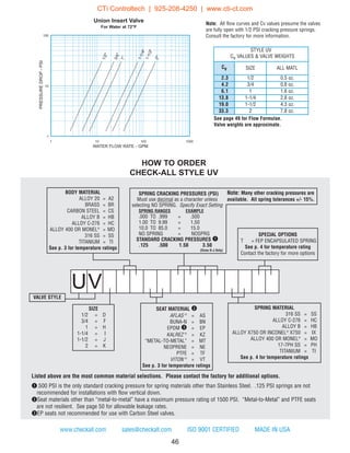
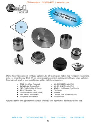
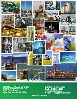

Check-All Valve® Manufacturing Company provides a comprehensive range of valves, focusing on efficient design and high-quality standards, including ISO 9001 certification. Their products cater to diverse applications with various materials and ratings, emphasizing features such as silent operation, reduced maintenance costs, and versatility as both check valves and low pressure relief valves. The company supports custom configurations and ensures compliance with multiple industry standards, promoting reliability and customer service.


