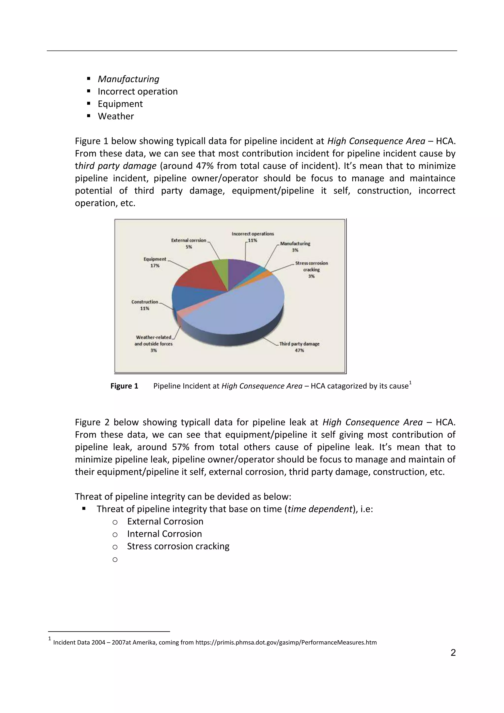
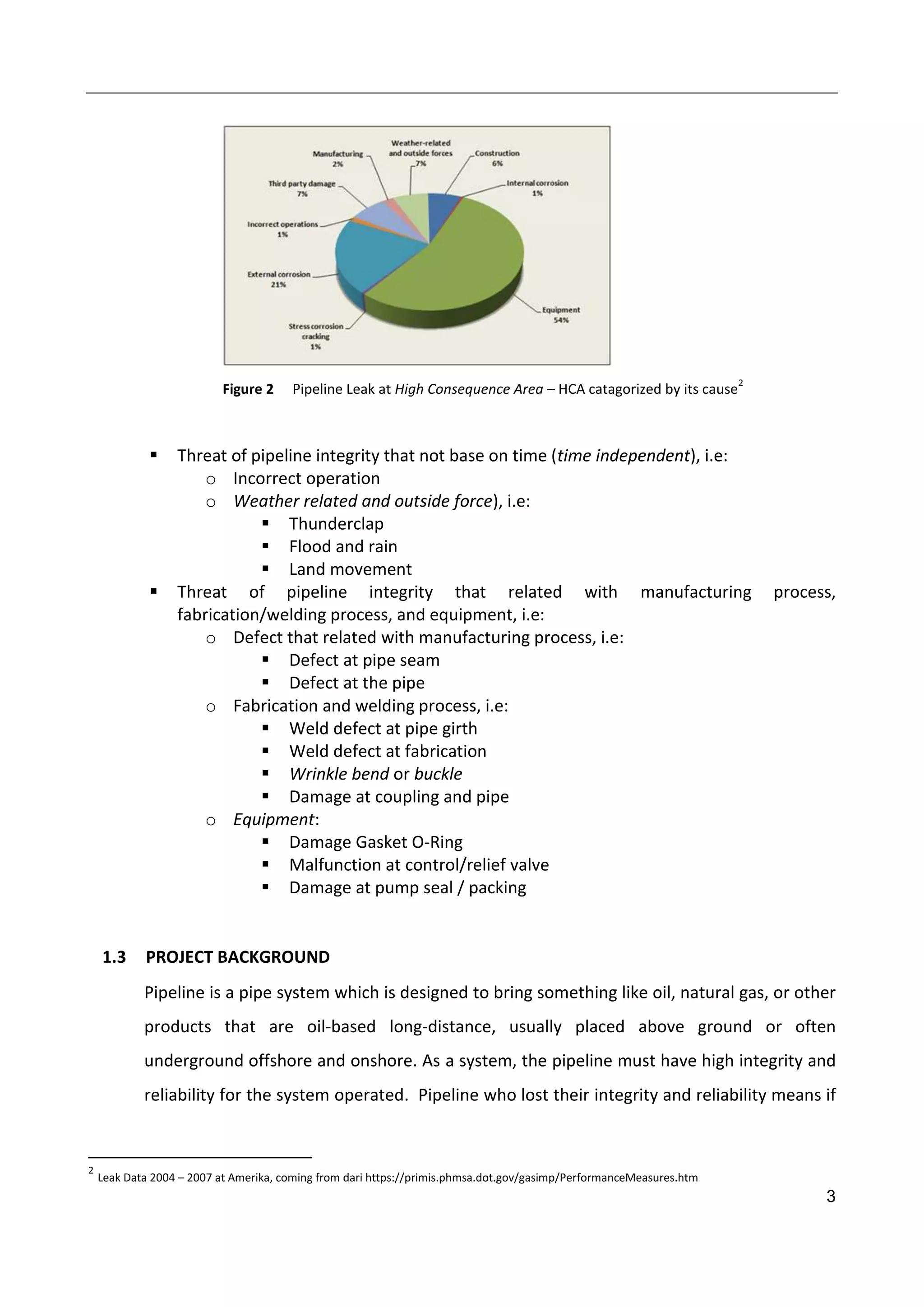
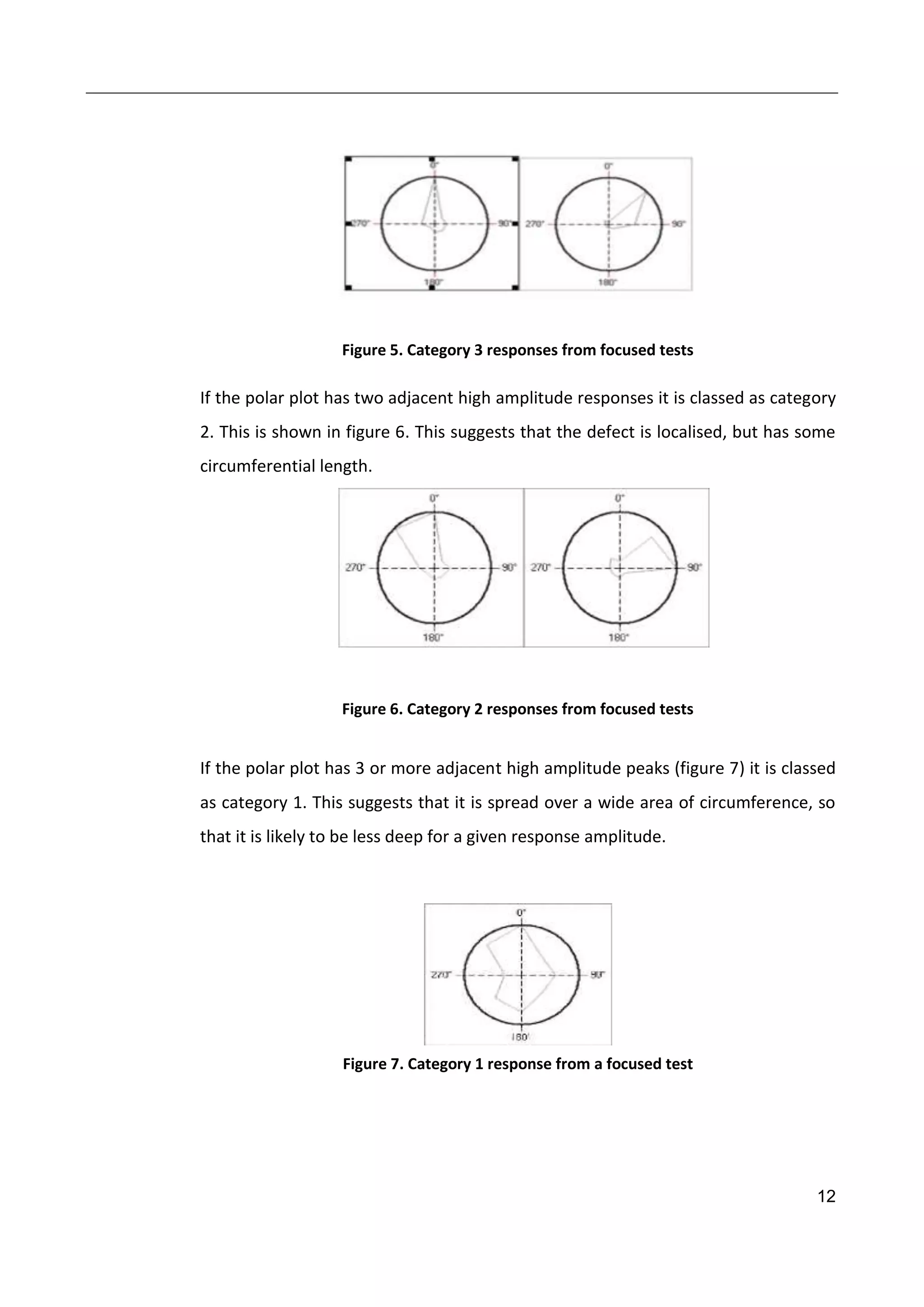
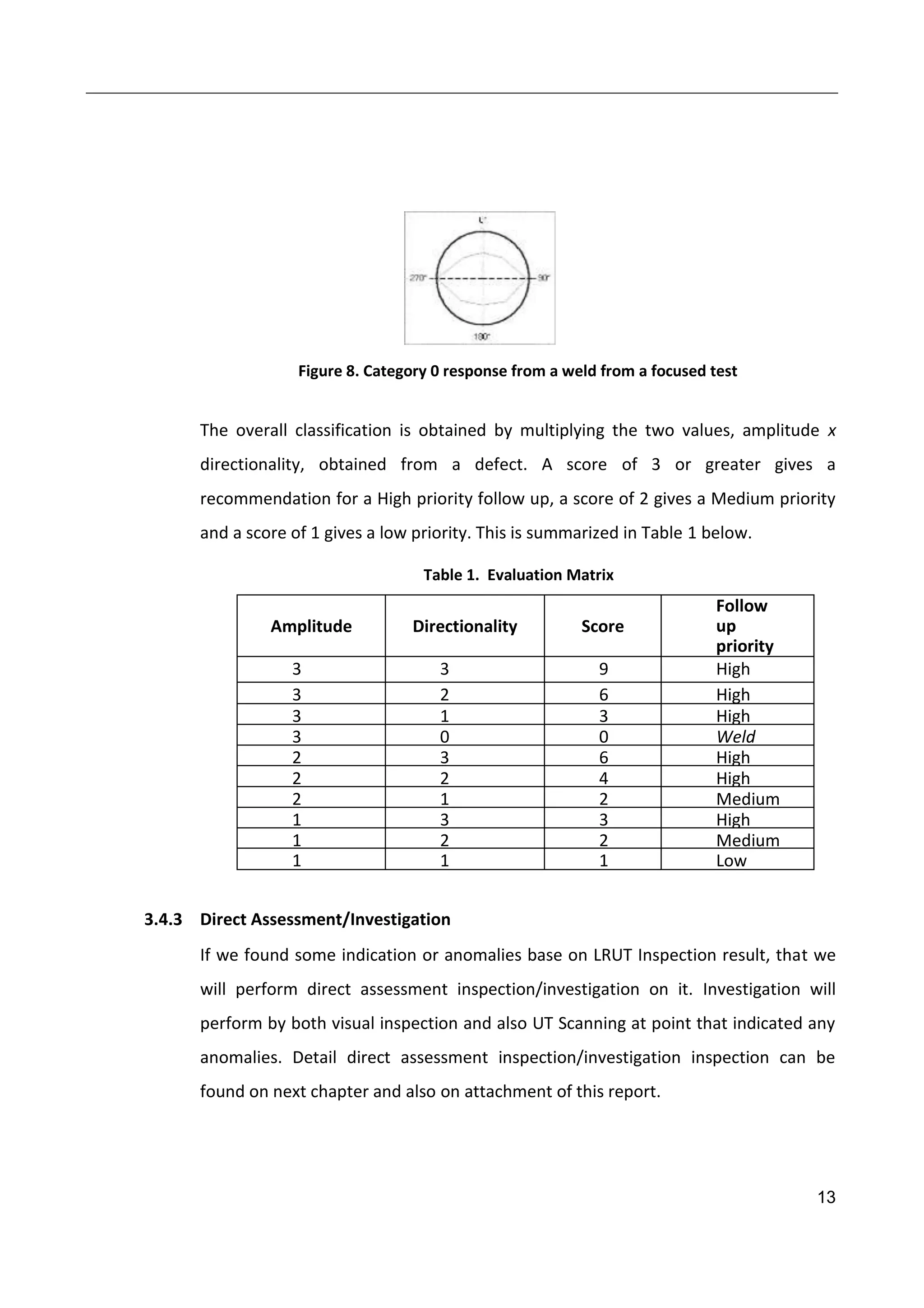
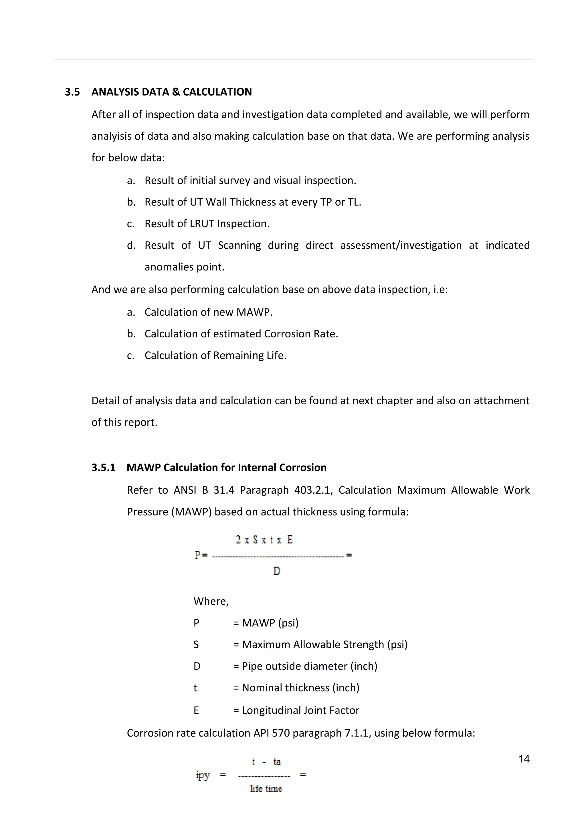
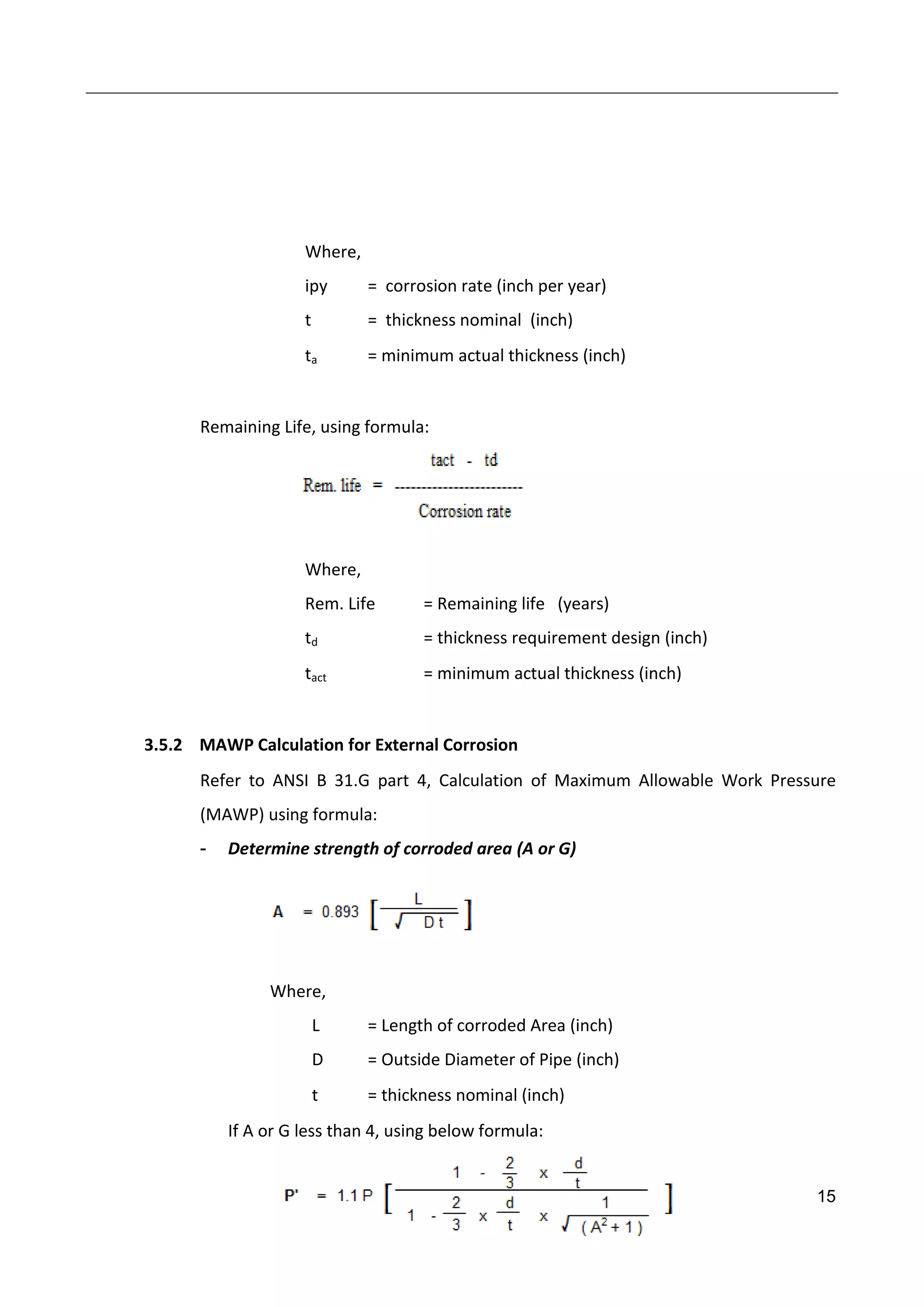
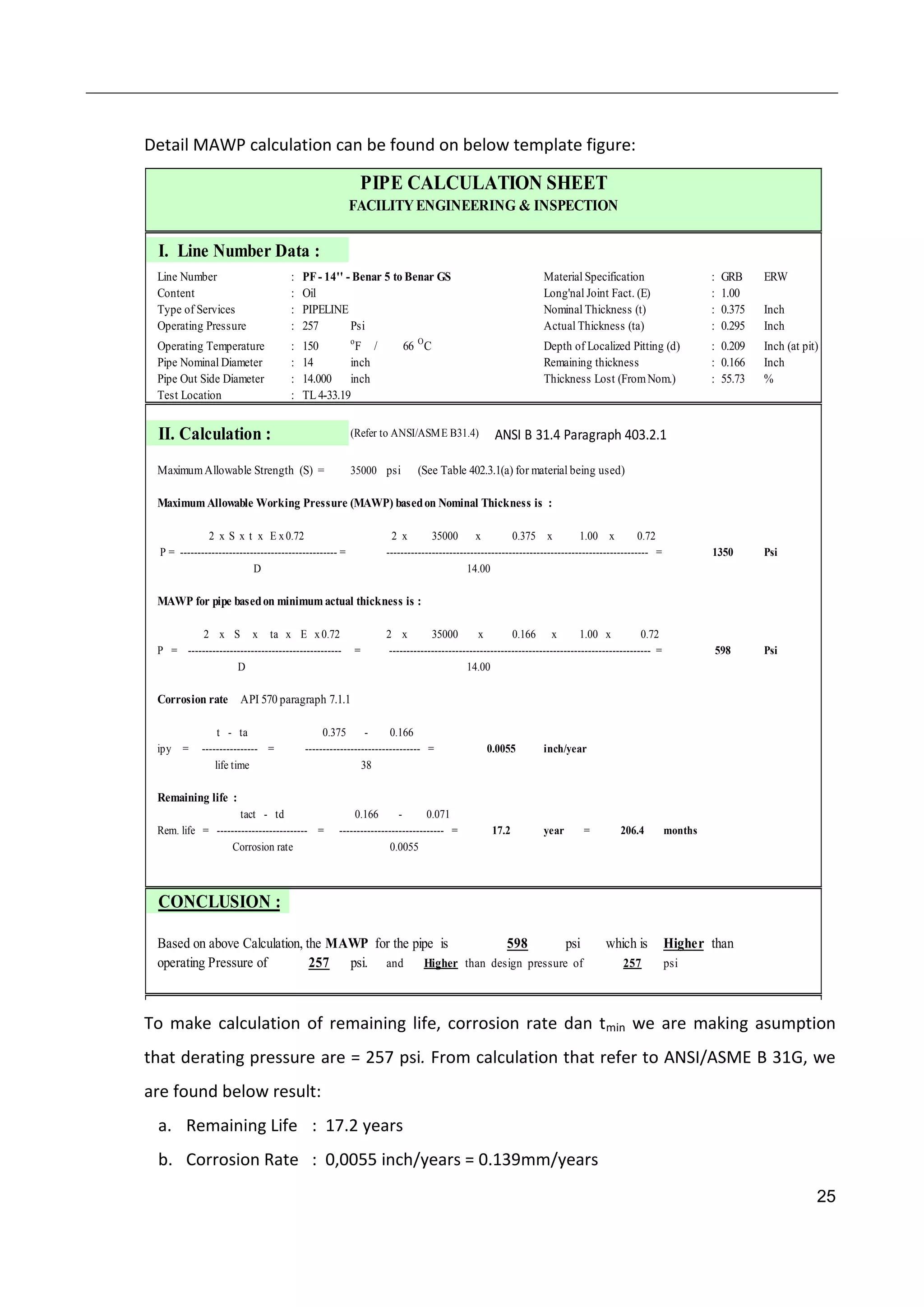
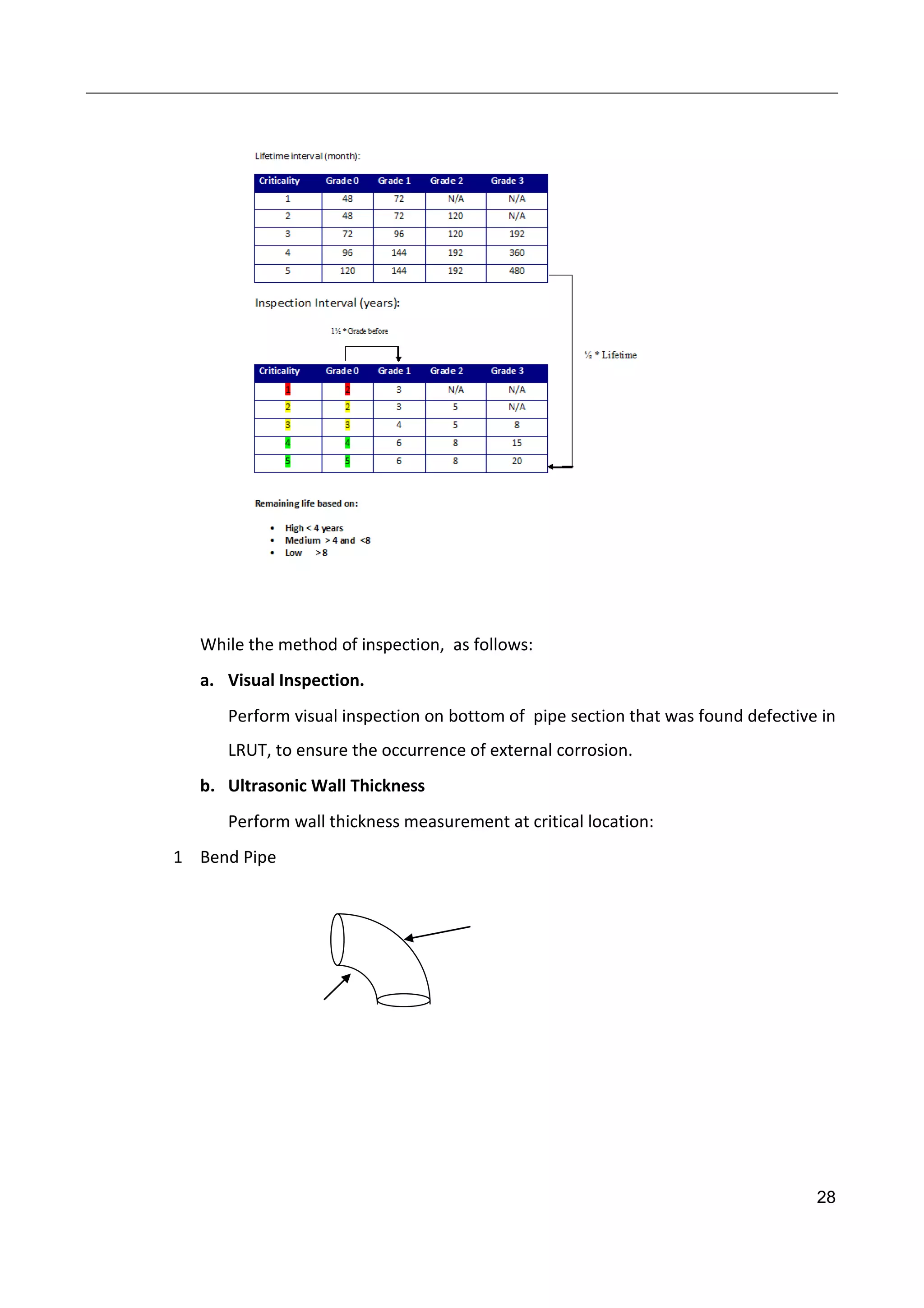
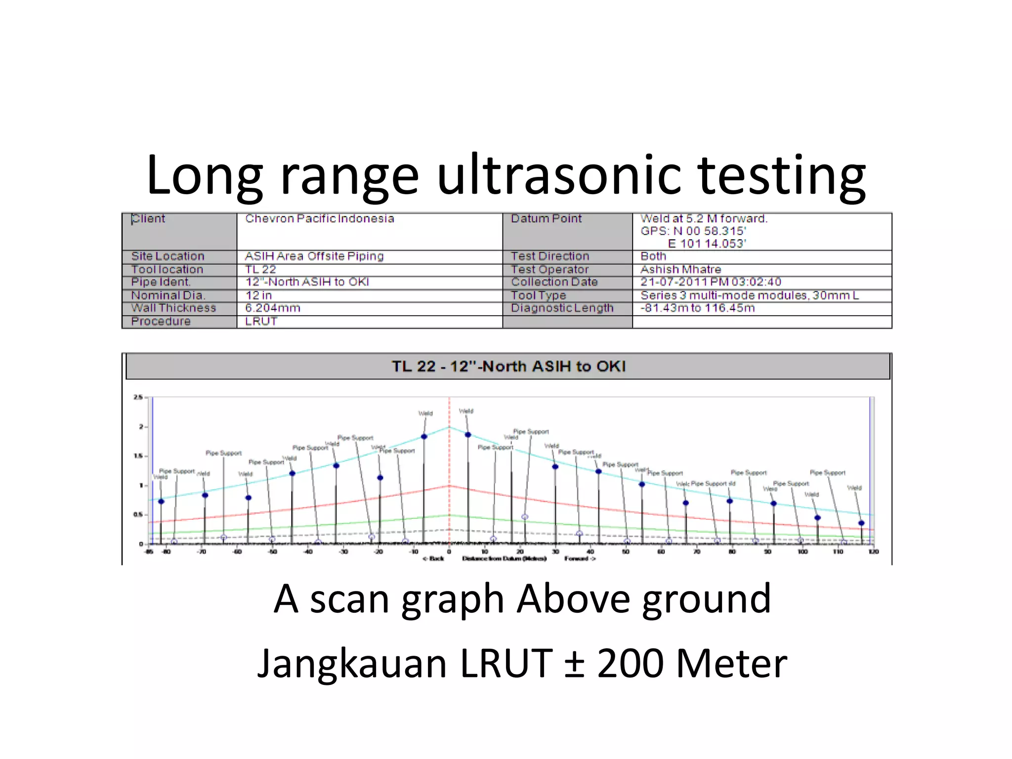
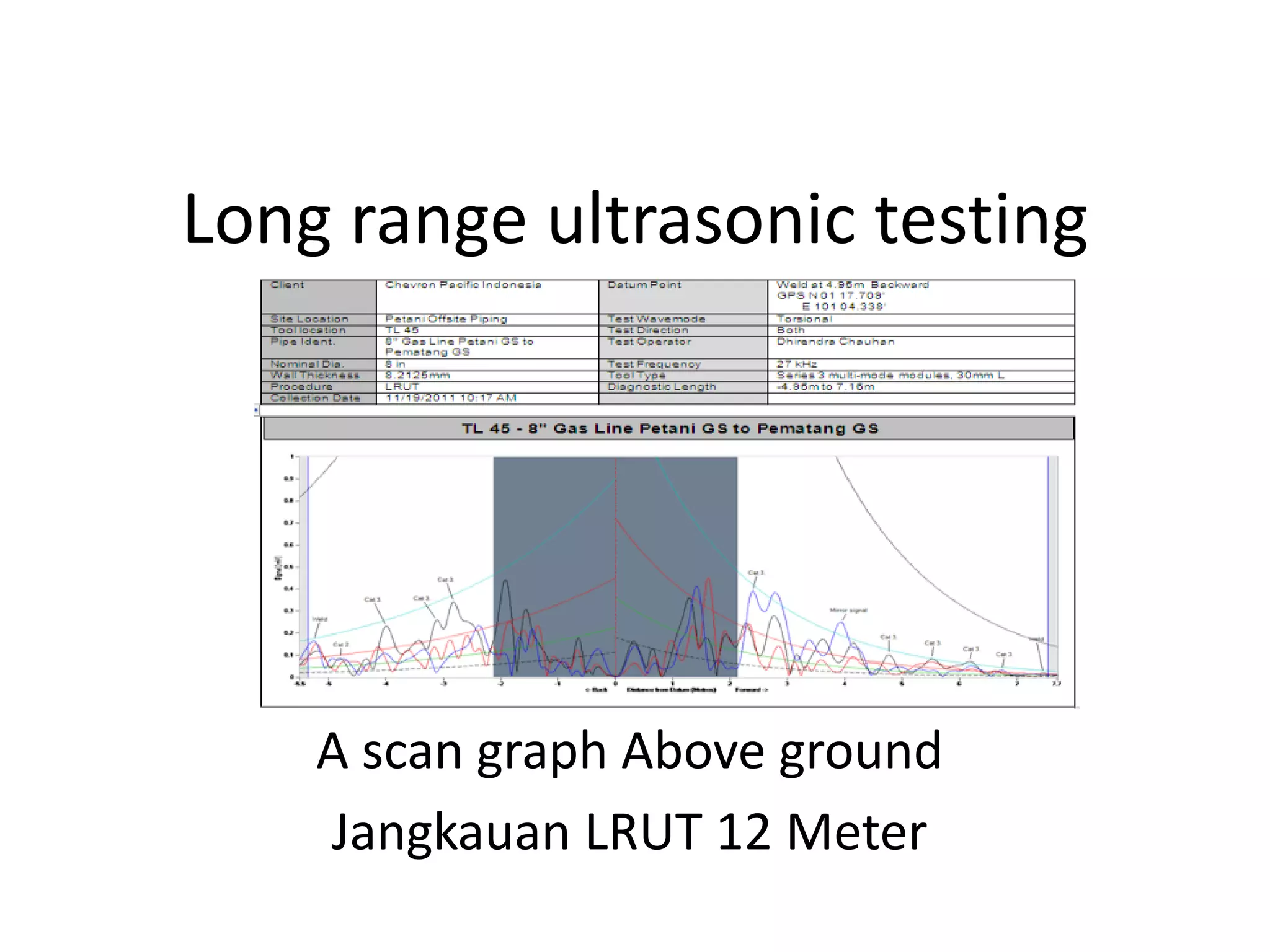
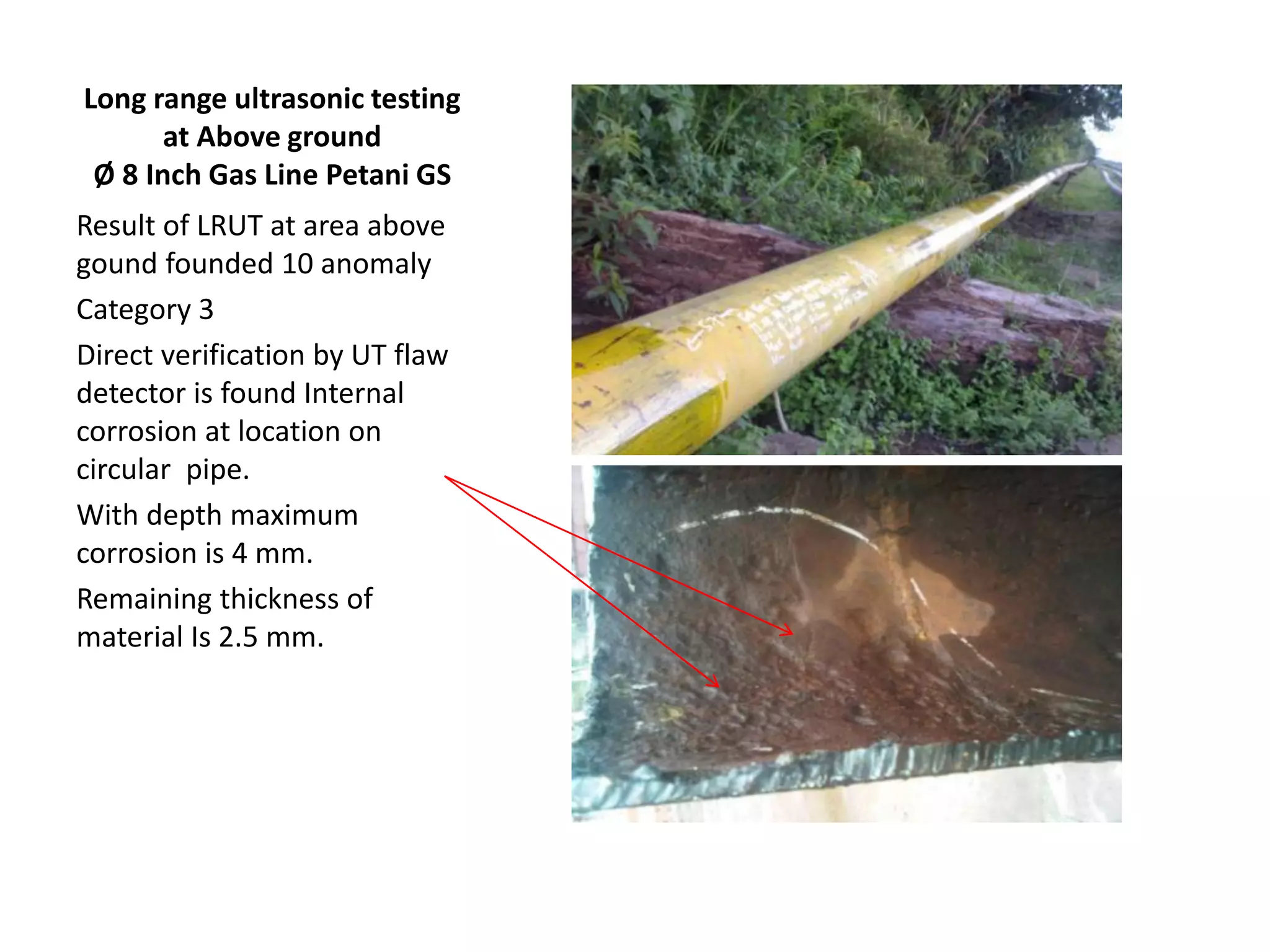
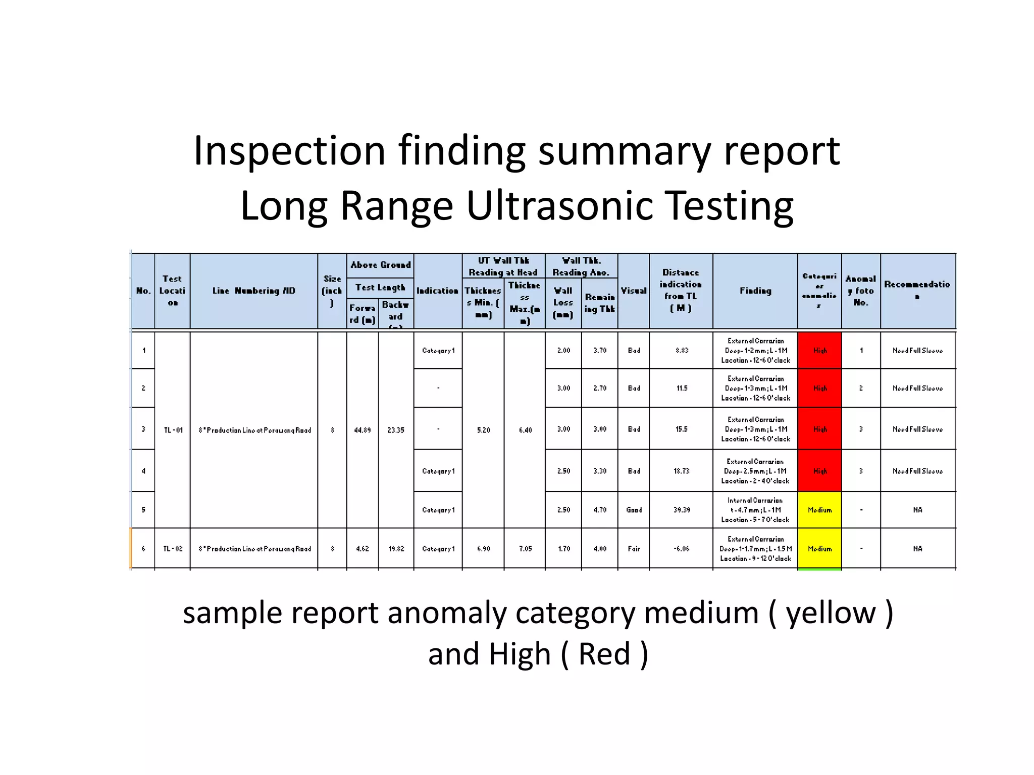
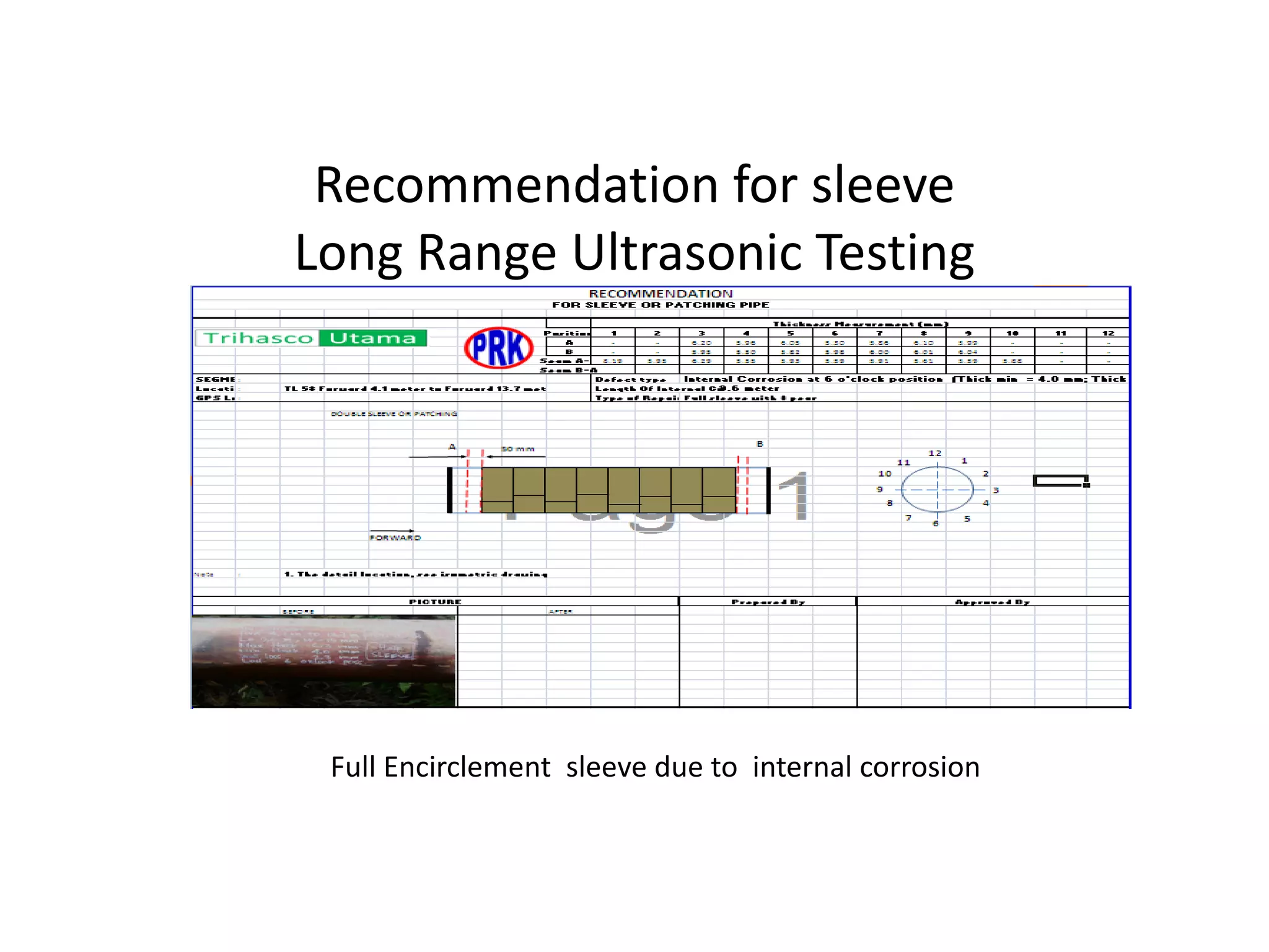
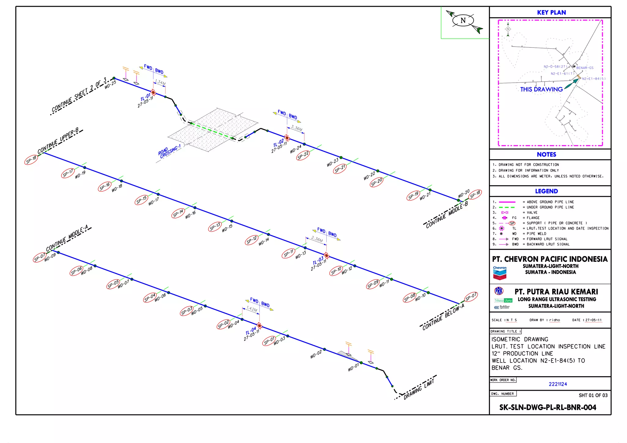
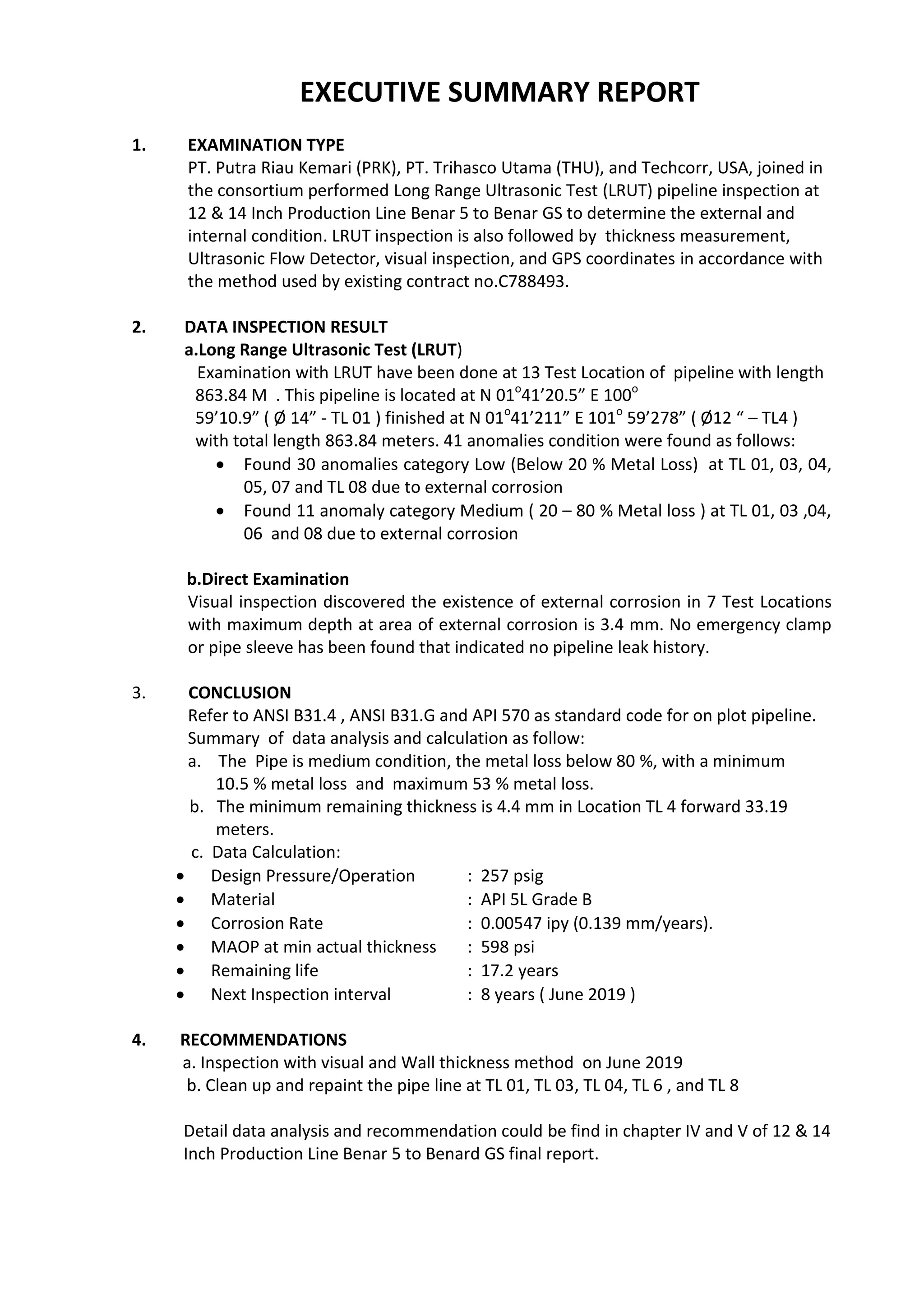
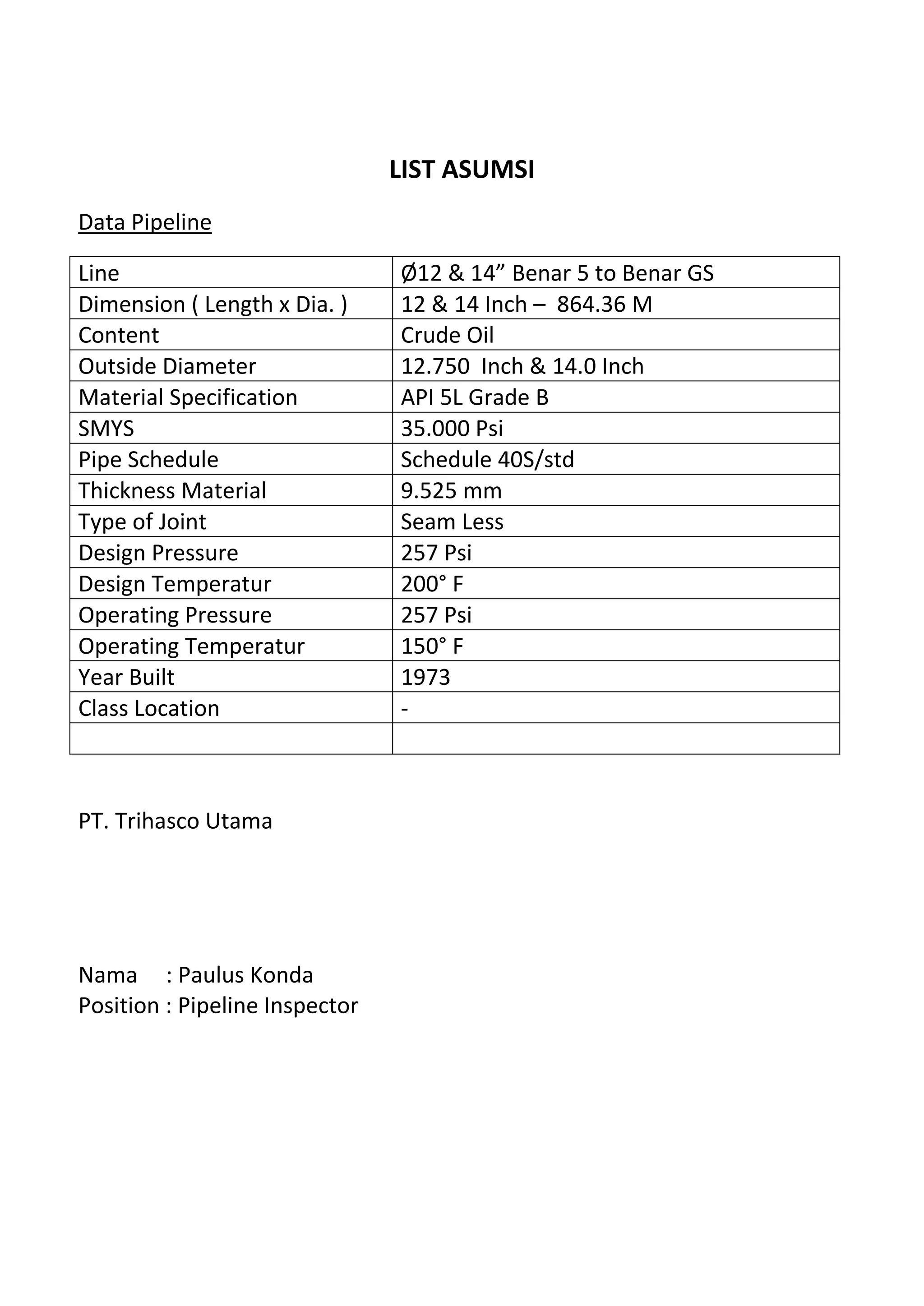
As a product of transportation facility, pipeline sould be having a good integrity. Pipeline failure means that pipeline can not operate both at some segment/section or all of pipeline segment can not deliver product/service as per their function. Or failure of pipeline also means loss of pipeline integrity for some segment pipeline section or all of segment pipeline.
(TARA) Talegaon Dabhade Call Girls Just Call 7001035870 [ Cash on Delivery ] ...
Pipeline integrity assessment with LRUT method
1. LONG RANGE
ULTRASONIC TESTING
( LRUT )
May 1
2020
As a product of transportation facility, pipeline sould be having a
good integrity. Pipeline failure means that pipeline can not
operate both at some segment/section or all of pipeline segment
can not deliver product/service as per their function. Or failure
of pipeline also means loss of pipeline integrity for some
segment pipeline section or all of segment pipeline.
PAULUS KONDA
PIPELINE INTEGRITY ASSESSMENT
2. 1
CHAPTER I INTRODUCTION
1.1 PIPELINE INTEGRITY INTRODUCTION
As a product of transportation facility, pipeline sould be having a good integrity. Pipeline
failure means that pipeline can not operate both at some segment/section or all of pipeline
segment can not deliver product/service as per their function. Or failure of pipeline also
means loss of pipeline integrity for some segment pipeline section or all of segment
pipeline.
Pipeline incident refer to gas release from pipeline can be gave consequence like
dead/fatality, injury, pollution, or property damage included loss that cause by gas release
with huge nominal value (typically value more than $ 50.000).
Pipeline leak refer to release of product/service from pipeline that not by design.
Consequence of pipeline leak can not cause dead/fatality and or serius injury, but in some
cases was happen. Most of pipeline leak consequences are loss of product/service,
environtment pollution, property loss and company image (typically value more than $
50.000).
Both pipeline incident and pipeline leak are happing consequence with high level of fatality.
Area with these categories usually knows as High Consequence Area – HCA.
By definition, pipeline that lacated at location class 3 and 4 are catagorized at High
Consequence Area – HCA. These areas were devided on two zones, i.e High Impact Zone
(zone with high impact) and Moderate Impact Zone (zone with moderate impact). If these
area were located at Potential Impact Zone – PIC than these area catagorized as high impact
zone, but if these area were located out of Potential impact Zone – PIC than catagorized as
moderate impact zone. But for pipeline that located at location class 1 and 2, high
consequence area defined with different manner.
In general, Potential Impact Zone having Threshold Radius – TR that calculated base on
Potential Impact Radius – PIR. Potential Impact Radius can be entented for the special
condition.
1.2 PIPELINE INCIDENT AND LEAK
There are some cause as trigger of incident and leak of pipeline, i.e:
Third party damage
Corrosion:
o Internal corrosion
o External corrosion
o Stress corrosion cracking
Construction
3. 2
Manufacturing
Incorrect operation
Equipment
Weather
Figure 1 below showing typicall data for pipeline incident at High Consequence Area – HCA.
From these data, we can see that most contribution incident for pipeline incident cause by
third party damage (around 47% from total cause of incident). It’s mean that to minimize
pipeline incident, pipeline owner/operator should be focus to manage and maintaince
potential of third party damage, equipment/pipeline it self, construction, incorrect
operation, etc.
Figure 1 Pipeline Incident at High Consequence Area – HCA catagorized by its cause
1
Figure 2 below showing typicall data for pipeline leak at High Consequence Area – HCA.
From these data, we can see that equipment/pipeline it self giving most contribution of
pipeline leak, around 57% from total others cause of pipeline leak. It’s mean that to
minimize pipeline leak, pipeline owner/operator should be focus to manage and maintain of
their equipment/pipeline it self, external corrosion, thrid party damage, construction, etc.
Threat of pipeline integrity can be devided as below:
Threat of pipeline integrity that base on time (time dependent), i.e:
o External Corrosion
o Internal Corrosion
o Stress corrosion cracking
o
1
Incident Data 2004 – 2007at Amerika, coming from https://primis.phmsa.dot.gov/gasimp/PerformanceMeasures.htm
4. 3
Figure 2 Pipeline Leak at High Consequence Area – HCA catagorized by its cause
2
Threat of pipeline integrity that not base on time (time independent), i.e:
o Incorrect operation
o Weather related and outside force), i.e:
Thunderclap
Flood and rain
Land movement
Threat of pipeline integrity that related with manufacturing process,
fabrication/welding process, and equipment, i.e:
o Defect that related with manufacturing process, i.e:
Defect at pipe seam
Defect at the pipe
o Fabrication and welding process, i.e:
Weld defect at pipe girth
Weld defect at fabrication
Wrinkle bend or buckle
Damage at coupling and pipe
o Equipment:
Damage Gasket O-Ring
Malfunction at control/relief valve
Damage at pump seal / packing
1.3 PROJECT BACKGROUND
Pipeline is a pipe system which is designed to bring something like oil, natural gas, or other
products that are oil-based long-distance, usually placed above ground or often
underground offshore and onshore. As a system, the pipeline must have high integrity and
reliability for the system operated. Pipeline who lost their integrity and reliability means if
2
Leak Data 2004 – 2007 at Amerika, coming from dari https://primis.phmsa.dot.gov/gasimp/PerformanceMeasures.htm
5. 4
not ability to operate and is below the minimum requirement allowed by the code /
standard or owner specification used.
If still ignored by the conditions below minimum requirements, the pipe will someday be a
failure at the time later or at the time that was not suspected. As a result of this failure
would have broad impact on economic value, safety and human health, and cause
disruption to the environment. The cause of failure in the pipeline caused by several
factors index, as follows:
Third party damaged index
Design index
Incorrect operation index
Corrosion index
The combination of the impact of failure or the consequences of failure (CoF) to the cause
of the failure or the probability of failure (PoF) is a risk. The higher of the consequences of
failure and the probability of failure in a pipeline means higher risks for the operation.
Risk = CoF x PoF
Various methods used to mitigate these variables to minimize the risks. To mitigate the
consequences of failure should the policies of the management authority of the owner of
the pipeline that will impact on all sectors in the company in a long time, these
considerations need to be a long time, and complicated.
Mitigate the probability of failure is not as complicated as compared to mitigate the
consequences of failure, but it also takes preparation. Mitigate the probabilities of failure,
as follows:
Supervision and oversight in the initial design fabrication process.
Documenting the design data after completed the fabrication process.
Monitoring and maintaining operational conditions, perform maintenance
and repair of facilities in the Right Of Way (ROW) and the pipe itself.
6. 5
Monitoring the condition pipe with a potentially damaged by the activities
of third parties as well as create educational programs in the community
about hazard potential
Create a plan for inspection at the appropriate time and appropriate
method of inspection in accordance with the mode of failure in the pipeline.
Related one of the efforts to mitigate probabilities of failure mentioned above is to make
an inspection plan with appropriate method, Chevron Pacific Indonesia (CPI) has made an
inspection plan in the period 2011/2012 using the method of Long Range Ultrasonic (LRUT)
to detect any defects in pipe material caused by corrosion or erosion.
For executive jobs LRUT, the CPI has conducted a tender to the contractors. PT. Putra Riau
Kemari (PRK), PT. Trihasco Utama (THU), and Techcorr, USA, joined in the consortium
appointed as the winner of the tender. With no C 788 493 contract, the consortium
running the project will serve the work area CPI. Results from LRUT will be verified with a
manual ultrasonic, the data obtained will be reported in this report in engineering
calculations to obtain the value of maximum allowable working pressure (MAWP),
corrosion rate, as well as the recommendations included suggestions to repair the pipe if it
is found that critical area.
1.4 PORPOSE
Purpose of the job "Long Range Ultrasonic Testing (LRUT) Project" is to determine the
external and internal condition of pipes in the CPI and provide recommendations to the
CPI for repair and replacement of pipes when the pipe is not acceptable to operate
according to the code / standard that is used.
Scope of executive summary report is only for segment PF-12 & 14 Inch Benar 45 to
Bekasap GS, with total length is 863.84 meters
7. 6
1.5 WORK ORDER NUMBER
This report to be submitted for Work Order/JDE Number: 2218826 with scope of area
inspection only for PF-12 and 14 inch –Benar 5 to Benar GS.
1.6 TECHNICAL DATA
Area : Benar, SLN
Segment/ Length of Pipe : 12 and 14 Inch – Benar 5 to Benar GS / 863.84 meters
Fluid Content : Crude Oil
Outside Diameter : 12.750 inch and 14 Inch
Material Specification : API 5L Grade B
Nominal Thickness : 9.525 mm
Construction : Aboveground and Road Crossing
Design Press/Temp : 257 psi/ 200 o
F
Operating Press/Temp : 257 psi/ 150 o
F
The data obtained from the CPI and the CPI has been approved above data if that is the
data assumption.
8. 7
CHAPTER II SCOPE OF WORK & EQUIPMENT
2.1. SCOPE OF WORK
The scope of work for WO No. 2221124 in the area Sumatra Light North (SLN) Benar, is as
follows:
Survey and field data collection
Preparing Standard Operating Procedure (SOP) above ground
Preparing LRUT equipment
Preparing General Work Permit
LRUT analyze data, and classify categories of analysis.
Follow-up and verification, if found anomalies in the results LRUT analysis,
using a manual ultrasonic scanning (internal corrosion indication) or visual
(external corrosion indication).
Record minimum remaining thickness and reporting result verification
data.
Calculating data to determine corrosion rate, MAWP and remaining life.
Recommendation.
2.2. EQUIPMENT & TOOLS
Equipment:
1 set LRUT with collar size 8 inch
Thermometer gun infrared
UT Wall thickness : Cygnus
UT Scanning : DMS-2
Global Positioning System (GPS): Garmin
Tools:
Gas Detector
Hoe
Shovel
Sandpaper
9. 8
CHAPTER III INSPECTION METHODOLOGY
3.1 PREPARATION OF JOB
For this project, there are some of task that included as preparation of job, i.e:
Daily coordination with all of team member before executes the job.
Preparation of working permit every day at site.
Preparation of inspection equipment and tools for this job.
Safety briefing if we execute new work order.
3.2 INITIAL FIELD SURVEY
Propose of initial survey is:
a. Performing initial general screening propose to know where is pipeline location and
road acess as reference of team and equipment mobilization.
b. Performing initial visual inspection along the pipeline to know external surface
condition of pipeline.
c. To know condition of pipeline system protection for underground pipeline,
withness land slide potential, free span potential, pipe support condition, etc.
3.3 COLLECTING DOCUMENT
Collecting data related with pipeline were perfomed together with CPI counterpart. These
data very important to know the history of pipeline design, operation, inspection and
maintenance.
Related data that we hope can be collected from pipeline owner and using as our
reference during analysis and calculation data are:
Alignment Sheet
Data design of pipeline
Historical of inspection report and ROW Survey
Report of last UT Wall Thickness
Maintenance/Repair Record
Operation Report
10. 9
Historical data of repair and pipe replacement
Soil Movement data (if any)
3.4 FIELD DATA COLLECTION
3.4.1 Visual Inspection and UT Wall Thickness
Visual inspection performed as method to screening surface condition of pipeline
segment. These conventional inspection methods are effective enough to screening
of potential damage that probably happen at existing pipeline. The Potential
damage included external general corrosion, extrem metal loss, erosion, blisters,
dents-gouges- combination dents gauges or pitting / flaw corrosion.
UT Wall Thickness performed at every Test point (TP) or Test Location (TL) at 4
location (at 12 o’clock, at 3 o’clock, at 6 o’clock, and at 9 o’clock). But to make sure
that LRUT dead zone are also screening, we were performed UT wall thickness
inspection forward and backward every 1 ft, but data not recorded due to porpose
of inspection only to make sure pipeline condition at LRUT dead zone. If we found
any anomalies or indication during that inspection, we will performing direct
assessment/investigation on it.
Figure 3. LRUT Inspection
Detail result of UT Wall Thickness Measurement at every TP or TL for this pipeline
can be found at attachment report.
3.4.2 Long Range Ultrasonic Testing (LRUT) Inspection
Indications identified on the A-scan plots are evaluated on the basis of a
combination of:
11. 10
1. The signal amplitude
2. The directionality of the focused response.
This takes into account that large amplitude responses will be from a large cross-
sectional area defect. Small defects cannot produce large amplitude reflections.
However, the converse is not always true; a small amplitude response does not
necessarily mean that the defect is small, as the response may be affected by a
number of factors.
In order to provide a means of identifying defects which are potentially significant
in terms of the integrity of the pipe it is also necessary to examine how localized the
response is in terms of the pipe circumference. This may be obtained from the
focused tests and is plotted on a polar response chart.
To incorporate these changes, some aspects of the interpretation procedure have
been altered compared with earlier versions of the Teletest®
test procedures:
Whereas the indications were previously assessed primarily in terms of amplitude,
with the categories being ‘Minor’, ‘Moderate’ and ‘Severe’, the signals are now
described as being of Amplitude Category 1, 2 or 3, with Category 3 being the
highest.
An additional DAC curve has been added to the analysis screen. This is a red line at -
20dB compared with a 100% reflector (equivalent to a pipe end), so that it plots in
between the blue weld line (-14dB) and the green 9% reflector line (-26dB). This
defines the boundary between Categories 2 and 3 - see below.
The additional DAC curve and the areas corresponding to the categories above are
shown in Figure 4, below.
12. 11
Figure 4. Schematic of the Teletest A-scan, showing the amplitude categories.
Category 1 responses are those which are lower than the green -26dB line (formerly
minor). Category 2 responses are those above the -26dB line, but are lower than
the new red line at -20dB (formerly Moderate). Category 3 responses exceed the
new red -20dB line (these are broadly the same as the previous severe
classification, but the limiting amplitude is now better defined.
Below the Greenline is category 1, between the green and red line is category 2 and
above the red is category 3. The collection of focused data from suspected defects
is an integral part of the test regime. The results from focused tests on each defect
are analyzed in terms of the directionality of the response.
If the polar plot shows a high level of directionality, indicated by a single peak in the
plot at one focus angle, it is classed as category 3 (figure 5). This indicates that the
defect is highly localized on a narrow part of the circumference, so that it is likely to
be deep for given amplitude of response.
13. 12
Figure 5. Category 3 responses from focused tests
If the polar plot has two adjacent high amplitude responses it is classed as category
2. This is shown in figure 6. This suggests that the defect is localised, but has some
circumferential length.
Figure 6. Category 2 responses from focused tests
If the polar plot has 3 or more adjacent high amplitude peaks (figure 7) it is classed
as category 1. This suggests that it is spread over a wide area of circumference, so
that it is likely to be less deep for a given response amplitude.
Figure 7. Category 1 response from a focused test
14. 13
Figure 8. Category 0 response from a weld from a focused test
The overall classification is obtained by multiplying the two values, amplitude x
directionality, obtained from a defect. A score of 3 or greater gives a
recommendation for a High priority follow up, a score of 2 gives a Medium priority
and a score of 1 gives a low priority. This is summarized in Table 1 below.
Table 1. Evaluation Matrix
Amplitude Directionality Score
Follow
up
priority
3 3 9 High
3 2 6 High
3 1 3 High
3 0 0 Weld
2 3 6 High
2 2 4 High
2 1 2 Medium
1 3 3 High
1 2 2 Medium
1 1 1 Low
3.4.3 Direct Assessment/Investigation
If we found some indication or anomalies base on LRUT Inspection result, that we
will perform direct assessment inspection/investigation on it. Investigation will
perform by both visual inspection and also UT Scanning at point that indicated any
anomalies. Detail direct assessment inspection/investigation inspection can be
found on next chapter and also on attachment of this report.
15. 14
3.5 ANALYSIS DATA & CALCULATION
After all of inspection data and investigation data completed and available, we will perform
analyisis of data and also making calculation base on that data. We are performing analysis
for below data:
a. Result of initial survey and visual inspection.
b. Result of UT Wall Thickness at every TP or TL.
c. Result of LRUT Inspection.
d. Result of UT Scanning during direct assessment/investigation at indicated
anomalies point.
And we are also performing calculation base on above data inspection, i.e:
a. Calculation of new MAWP.
b. Calculation of estimated Corrosion Rate.
c. Calculation of Remaining Life.
Detail of analysis data and calculation can be found at next chapter and also on attachment
of this report.
3.5.1 MAWP Calculation for Internal Corrosion
Refer to ANSI B 31.4 Paragraph 403.2.1, Calculation Maximum Allowable Work
Pressure (MAWP) based on actual thickness using formula:
Where,
P = MAWP (psi)
S = Maximum Allowable Strength (psi)
D = Pipe outside diameter (inch)
t = Nominal thickness (inch)
E = Longitudinal Joint Factor
Corrosion rate calculation API 570 paragraph 7.1.1, using below formula:
16. 15
Where,
ipy = corrosion rate (inch per year)
t = thickness nominal (inch)
ta = minimum actual thickness (inch)
Remaining Life, using formula:
Where,
Rem. Life = Remaining life (years)
td = thickness requirement design (inch)
tact = minimum actual thickness (inch)
3.5.2 MAWP Calculation for External Corrosion
Refer to ANSI B 31.G part 4, Calculation of Maximum Allowable Work Pressure
(MAWP) using formula:
- Determine strength of corroded area (A or G)
Where,
L = Length of corroded Area (inch)
D = Outside Diameter of Pipe (inch)
t = thickness nominal (inch)
If A or G less than 4, using below formula:
17. 16
Where,
P’ = MAWP Corroded Area (psi)
P = Design Pressure based nominal thickness (psi)
D = depth of pitting (inch)
t = thickness nominal (inch)
If A or G greater than 4, using below formula:
Where,
P’ = MAWP Corroded Area (psi)
P = Design Pressure based nominal thickness (psi)
3.6 CONCLUTION & RECOMMENDATION PREPARATION
3.6.1 Conclution
The conclusions given in this report is the actual condition of the pipeline after
application of above inspection methodology, i.e: initial field survey, visual
inspection, UT Wall Thickness, LRUT, and direct assessment (UT Scanning and Depth
Gauge if there is pitting corrosion found).
3.6.2 Recommendation
Some of the recommendations that will be recommended on this report consider
the following:
If Metal loss of pipe less than or maximum 20% of thickness required
design.
18. 17
In these conditions, the recommendation given is an inspection plan that
considers the results of the calculation of remaining life. Basically, the
calculation of remaining life is only for the age-related corrosion condition,
while condition base is the result of remaining life multiple confidence rating
and is focus on individual pipeline. Thickness measurements should be
scheduled based on the calculation of not more than half the remaining life
determination.
An area of corrosion with maximum depth greater than 20% but less than or
equal to 80% of the wall thickness.
In these condition, conducted the evaluation using the ASME B. 31.G, and the
corrected thickness plus Corrosion Allowance. If that fails will be recommended
to the mounting sleeve type A or composite sleeve temporary.
An area of corrosion with more than 80% of the wall thickness.
In these conditions, the pipe shall be removed or repaired.
All of these conditions are illustrated in the diagram below:
19. 18
Figure 9. Repair for internal corrosion
Figure 10. Repair for external corrosion
Detail recommendation will be explained at Chapter V at this report.
20. 19
CHAPTER IV RESULT, ANALYSIS AND CALCULATION
4.1 INITIAL SURVEY & VISUAL INSPECTION RESULT
Surveys have been conducted in the area Bekasap, SLN Ø12 and 14 Inch- Benar 5 to Benar
GS, with total length 863.84 meters, and getting conditions of the pipeline.
The survey results above are used by CPI as reference to issued WO No. 2218826
Survey result base on visual inspection/naked eye inspection during initial survey are:
1. In general, pipeline was constructed above ground
2. Pipeline in coated condition
3. There are not found leak or sleeve or patching.
4. This pipeline segment has 2 road crossing and the protected by casing.
4.2 LONG RANGE ULTRASONIC TESTING (LRUT) RESULT
Our main method of inspection for this job is Long Range Ultrasonic Test (LRUT) inspection.
Porpose of LRUT inspection are to screening pipeline condition both external and internal
condition at the same time. LRUT inspection performed and applied for all of pipeline SLN
12 and 14 Inch Benar 5 to Benar GS, with total length 863.84 meters. Before shooting of
LRUT performed, we are devide some Test Point (TP) or Test Location (TL) where LRUT
shooting will be done. Because porpose of this job are to screening 100% pipeline
condition, than TP/TL second and onward depend on result length of LRUT shooting for
first TP/TL.
Below, step by step explanation LRUT inspection:
1. Indicated first Test Point (TP) or Test Location (TL).
2. Cleaning location TP/TL, open coating (wrapping tape)/insulation around 30 - 40 cm
(if any.
3. Visual inspection at pipeline around TP/TL.
4. Collecting data UT wall thickness at 4 locations (at 12 o’clock, 3 0’clock, 6 o’clock,
and 9 0’clock).
5. Install Collar Size Transducer at location that has been cleaning above (Test Point) ;
be carefull flow of oil (follow LRUT Expert instruction/sugestion).
6. Install cable to Collar Size Transducer, Compressor Data Logger dan Laptop.
21. 20
7. LRUT expert collecting data at that TP for forward and backward direction.
If LRUT expert found high priority (see table 1. Evaluation Matrix above), than we must
performing direct assessment/investigation at location were found anomalies/indication.
Mostly, indication that should be follow up by direct assessment/investigation are if
shooting result indicated found category 2 with ECSL : Estimated Cross Sectional Loss
around 9 – 16% from nominal thickness and also indication 3 with ECSL : Estimated Cross
Sectional Loss more than 16% from nominal thickness. Some equipment that we are use
during perform direct assessment/investigation are Manual UT Thickness, UT Scanning,
and Pitch Gauge (for check depth of corrosion and length of corroded area).
Below, we can found set up of LRUT Equipment that we were used for this job:
Figure 9. Set Up of LRUT Equipment
Below (table 3), we can found conclution of LRUT inspection result per TP for segment
pipeline SLN Ø 12 and 14 Inch Benar 5 to Benar GS, with total length 863.84 meters,
included their each anomalies indication.
Table 3. Resume of LRUT Result
22. 21
A G UG R C F wd (m) B wd (m) F wd ( m) B wd ( m )
D
(mm)
T
(mm)
L M H
External Pitting
Corossion
-2.46 1.8 - 100 50 Medium Pict 1
External Pitting
Corossion
-8.14 1.1 - 500 200 Low Pict 2
External Pitting
Corossion
-9.02 1.6 - 500 200 Low Pict 3
- -
External Pitting
Corossion
-11.86 1.1 - 100 100 Low Pict 4
External Pitting
Corossion
-22.50 2-2.5 - 200 150 Medium Pict 5
External Pitting
Corossion
-23.26 1.2 - 100 50 Low Pict 6
External Pitting
Corossion
+6.75 1.2 - 100 100 Low Pict 7
External Pitting
Corossion
+10-
13.40
1.6-3.4 - 3400 250 Medium Pict 8
-6.21 - - - - Low
-32.94 - - - - Low
3 Good -1.02 - - - - Low
External Pitting
Corossion
-14.18 1.2 - 50 50 Low Pict 9
External
Corossion
+3.77 2.5 - 2000 200 Medium Picy 10
Good +9.20 - - - - Low
Good +12.43 - - - - Low
Good +17.24 - - - - Low
- - Good +18.79 - - - - Low
680 24 12 Good +24.84 - - - - Low
Good +25.49 - - - - Low
External Pitting
Corossion
+27.52 1.7 - 700 200 Low Pict 11
External Pitting
Corossion
+31.11-
32
1.8-2.7 - 1000 200 Medium Pict 12
External Pitting
Corossion
35.69 1 - 50 50 Low Pict 13
External Pitting
Corossion
+37.18 1 - 50 50 Low Pict 14
External Pitting
Corossion
-33.19 2.4-3.3 - 1000 200 Medium Pict 15
External Pitting
Corossion
-40.40 1.4 - 50 50 Low Pict 16
External Pitting
Corossion
+11.17 1.4 - 50 50 Low Pict 17
External Pitting
Corossion
+15.17 2 - 50 59 Low Pict 18
External Pitting
Corossion
+21.77 1.5 - 50 50 Low Pict 19
External Pitting
Corossion
+26.36 1.5 - 200 200 Low Pict 20
Good -14.27 - - - - Low
Good -18.14 - - - - Low
- - 907 55.8 20
External Pitting
Corossion
-26.42 1 - 500 100 Low Pict 21
External Pitting
Corossion
-36.42 1.2 - 500 200 Low Pict 22
Tack Weld -18.14 - - - - Low Pict 23
6 TL 06 √ - -
N 01 41'31.6"
E100 59'03.9"
Paint 38.90 14.62 - - Category 2 7.50 8.00 709.00 26.80 13.00
External Pitting
Corossion
-5.75/
-11.49
2-2.5 - 6000 200 Medium Pict 24
7 TL 07 √
N 01 41'33.0"
E100 59'02.8"
Paint - 6.46 23.49 Category 1 8.70 9.50 1091.00 122.20 20.00
External Pitting
Corossion
-1.63 1 - 250 70 Low Pict 25
R/C lengh
23.49 M
External Pitting
Corossion
-5.57 1.4-2.2 - 750 1000 Medium Pict 26
External Pitting
Corossion
+1.40 -
'+1.68
1.8 -2.5 - 360 1000 Medium Pict 27
- - 774 34.1 17
External Pitting
Corossion
+2.30 1.6 -2 - 350 600 Medium Pict 28
External Pitting
Corossion
+2.80 1.3 -2 - 350 600 Medium Pict 29
External Pitting
Corossion
+3.40 1 - 750 600 Low Pict 30
9 TL 09 √ - -
N 01 41'34.4"
E100 59'02.0"
Paint 10.16 4.05
No Relevan
Indication
7.30 8.00 984.00 55.50 20.00 Good - - - - - Low
262.3 250.28 23.49 - 1
23.49 M
1 TL 01 √ - -
N 01 41.332'
E 101 59.194'
Paint 21.46 - - 15.68
No Relevan
Indication
6.32 6.98 984.00 55.50 20.00 Good - - - - - Low
2 TL 02 √ - -
N 01 41.322'
E 101 59.202'
Paint - 52.74 8.54 -
No Relevan
Indication
6.40 6.70 996.00 57.80 20.00 Good - - - - - Low
3 TL 03 √ - -
N 01 41.260'
E 101 59.244'
Paint 88.46 59.34 - -
No Relevan
Indication
6.47 6.57 996.00 57.80 20.00 Good - - - - - Low
TL 04 √ - -
N 01 41.211'
E 101 59.278'
Paint 50.91 30.63 - -
No Relevan
Indication
6.55 6.70 1016.00 61.80 20.00 Good - - - - - Low
160.83 142.71 1
24.23 M
N o .
T est
Lo catio n
C o nstructio n
C o o rdinats
P ipeline
P ipe
C o nditio n
T est Length
A bo ve gro und
T est Length
R o ad C ro ssing
TL 02 √ - -
N 01 41'22.6"
E100 59'09.4" Paint
14'' Production Line Benar 5 to Benar GS
1 TL 01 √ - -
N 01 41'20.5"
E100 59'10.9" Paint 44.7 14.02 10
1076 113.8 20
4 TL 04 √ - -
N 01 41'28.5"
E100 59'05.8" Paint
8 Good
TL 03 √ - -
N 01 41'25.4"
E100 59'08.0" Paint 46.85 52.34
39.18 47.53 - -
No Relevan
Indication
7.62
30.33 56.44 Category 1 & 2 7.5 7.7- -
Category 1 & 2 7.5 7.9
Paint 45.95 40.77 Category 1 7.6 85 TL 05 √ - -
N 01 41'30.5"
E100 59'04.6"
Paint 6.23 14.05 Category 1 & 2 7.95 8.18 TL 08 √ - -
N 01 41'33.1"
E100 59'03.0"
Total Length Pipe Line 303.54 24.23 Total Test Length Road Crossing
Total Road Crossing
Total Length Pipe Line 513.1 23.49 Total test Length Road Crossing
12'' Production Line Benar 5 to Benar GS
R/C
length
24.23M
Total Road Crossing
Category 1 & 2 8 8.3
A no maly
F o to N o .
R emark
Dist ance
f rom TL
M etal Lo ss
L
(mm)
W
(mm)
LR UT
C atego ry
Indicatio n
T hickness
M in.(mm)
T hickness
M ax.(mm)
Visual
F inding
A no maly F inding
598 17.2 8
M A WP
co rro ded
(psi)
R emaining
life
(year)
N ext
inspectio n
(year)
655 21.8
23. 22
Detail of LRUT result per TL including each their graph and interpretation for segment
pipeline Bekasap, SLN; Ø 12 and 14 Inch- Benar 5 to Benar GS, with total length 863.84
meters were described at attachment of this report.
Some of anomalies indication that we found for segment pipeline Bekasap, SLN; Ø 12 and
14 Inch Benar 5 to Benar GS, with total length 863.84 meters can be found at Direct
Assessment Report LRUT as below:
- Category 1 and 2 indication at TL 6
TL 06 - 14" Production Line
All of above anomalies indication should be investigated/performing direct assessment to
prove what actually happen at that location.
4.3 DIRECT ASSESSMENT/VERIFICATION RESULT
Base on data LRUT Result and also data indication of anomalies above, we are performing
direct assessment/investigation to make sure that what really happen at that point. Result
of investigation describe below:
24. 23
Table 3. Verification Result
No.
1
2
3
4
5
6
7
8
9
10
11
12
13
14
15
16
17
18
19
20
21
22
23
24
25
26
27
28
29
30
TL 08 Forward 2.80 meter
EXTERNAL COROSSION AT LOCATION FROM TL 08
FORWARD 2.80 M Depth = 1.3 - 2 mm, length 350 mm x 600 mm, position of
defect = 3 - 7 o’clock
TL 08 Forward 3.40 meter
EXTERNAL COROSSION AT LOCATION FROM TL 08
FORWARD 3.40 M Depth = 1mm, length 750 mm x 600 mm, position of
defect = 3 - 9 o’clock
TL 08 Forward 1.40 - 1.68 meter
EXTERNAL COROSSION AT LOCATION FROM TL 08
FORWARD 1.40 - 1.68 M Depth = 1.8 - 2.5 mm, length 360 mm x 1000 mm,
position of defect = 3 - 7 o’clock
TL 08 Forward 2.30 meter
EXTERNAL COROSSION AT LOCATION FROM TL 08
FORWARD 2.30 M Depth = 1.6 - 2 mm, length 350 mm x 600 mm, position of
defect = 3 - 7 o’clock
Ø 12'' & 14'' PRODUCTION LINE BENAR 5
TO BENAR GS
TL 07 TL 07 Backward 1.63 meter
EXTERNAL COROSSION AT LOCATION FROM TL 07
BACKWARD 1.63 M Depth = 1mm, length 250 mm x 70 mm, position of defect
= 6 o’clock
TL 08 Backward 5.57 meter
EXTERNAL COROSSION AT LOCATION FROM TL 08
BACKWARD 5.57 M Depth = 1.4 - 2.2 mm, length 750 mm x 1000 mm, position
of defect = 3 - 9 o’clock
Ø 12'' & 14'' PRODUCTION LINE BENAR 5
TO BENAR GS
TL 08
TL 05 Backward 18.14 meter
TAG WELD AT LOCATION FROM TL 05
BACKWARD 18.14
Ø 12'' & 14'' PRODUCTION LINE BENAR 5
TO BENAR GS
TL 06 TL 06 Backward 18.14 meter
EXTERNAL COROSSION AT LOCATION FROM TL 06
BACKWARD 5.75 - 11.49 M Depth = 2 - 2.5 mm, length 6000 mm x 200 mm,
position of defect = 4 - 6 o’clock
Ø 12'' & 14'' PRODUCTION LINE BENAR 5
TO BENAR GS
TL 05
TL 05 Backward 26.42 meter
EXTERNAL COROSSION AT LOCATION FROM TL 05
BACKWARD 26.42 M Depth = 1mm, length 500 mm x 100 mm, position of
defect = 6 o’clock
TL 05 Backward 36.42 meter
EXTERNAL COROSSION AT LOCATION FROM TL 05
BACKWARD 36.42 M Depth = 1.2 mm, length 500 mm x 200 mm, position of
defect = 5 - 8 o’clock
TL 04 Forward 21.77 meter
EXTERNAL COROSSION AT LOCATION FROM TL 04
FORWARD 21.77 M Depth = 1.5 mm, length 50 mm x 50 mm, position of defect
= 6 o’clock
TL 04 Forward 26.36 meter
EXTERNAL COROSSION AT LOCATION FROM TL 04
FORWARD 26.36 M Depth = 1.5 mm, length 200 mm x 200 mm, position of
defect = 4 - 6 o’clock
Ø 12'' & 14'' PRODUCTION LINE BENAR 5
TO BENAR GS
TL 04
TL 04 Forward 11.17 meter
EXTERNAL COROSSION AT LOCATION FROM TL 04
FORWARD 11.17 M Depth = 1.4 mm, length 50 mm x 50 mm, position of defect
= 6 o’clock
TL 04 Forward 15.17 meter
EXTERNAL COROSSION AT LOCATION FROM TL 04
FORWARD 15.17 M Depth = 2 mm, length 50 mm x 50 mm, position of defect =
7 o’clock
TL 04 Backward 33.19 meter
EXTERNAL COROSSION AT LOCATION FROM TL 04
BACKWARD 33.19 M Depth = 2.4 - 3.3 mm, length 1000 mm x 200 mm,
position of defect = 6 o’clock
TL 04 Backward 40.40 meter
EXTERNAL COROSSION AT LOCATION FROM TL 04
BACKWARD 40.40 M Depth = 1.4 mm, length 50 mm x 50 mm, position of
defect = 6 o’clock
TL 03 Forward 35.69 meter
EXTERNAL COROSSION AT LOCATION FROM TL 03
FORWARD 35.69 M Depth = 1mm, length 50 mm x 50mm, position of defect
= 6 o’clock
TL 03 Forward 37.18 meter
EXTERNAL COROSSION AT LOCATION FROM TL 03
FORWARD 37.18 M Depth = 1mm, length 50 mm x 50 mm, position of defect =
9 o’clock
Ø 12'' & 14'' PRODUCTION LINE BENAR
5 TO BENAR GS
TL 03
EXTERNAL COROSSION AT LOCATION FROM TL 03
FORWARD 27.52 M Depth = 1.7 mm, length 700mm x 200mm, position of
defect = 3 - 9 o’clock
TL 03 Forward 31.11 meter
EXTERNAL COROSSION AT LOCATION FROM TL 03
FORWARD 31.11M Depth = 1.8 - 2.7 mm, length 1000mm x 200mm, position
of defect = 6 o’clock
TL.01
Ø 12'' & 14'' PRODUCTION LINE BENAR
5 TO BENAR GS
TL 03 Forward 3.77 meter
INTERNAL COROSSION AT LOCATION FROM TL 03
FORWARD 3.77 M Depth = 2.5 mm, length 2000mm x 200mm, position of
defect = 5 - 7 o’clock
TL 01 Forward 10 - 13.40 meter
EXTERNAL CORROSION AT LOCATION FROM TL 01
BACKWARD 9.02 M
Depth = 1.6 mm, length 500 mm x 200mm , position of defect = 6 o’clock
EXTERNAL CORROSION AT LOCATION FROM TL 01
BACKWARD 11.86 M
Depth = 1.1mm, length 100 mm x 100mm , position of defect = 6 o’clock
EXTERNAL CORROSION AT LOCATION FROM TL 01
BACKWARD 22.50 M Depth = 2 - 2.5 mm, length 200 mm x 150mm , position of
defect = 7 o’clock
EXTERNAL CORROSION AT LOCATION FROM TL 01
BACKWARD 23.26 M
Depth = 1.2 mm, length 100 mm x 50mm , position of defect = 6 o’clock
EXTERNAL CORROSION AT LOCATION FROM TL 01
FOWARD 6.75 M
Depth = 1.2 mm, length 100 mm x 100mm , position of defect = 6 o’clock
EXTERNAL CORROSION AT LOCATION FROM TL 01
BACKWARD 8.14 M
Depth = 1.1mm, length 500 mm x 200mm , position of defect = 6 o’clock
EXTERNAL COROSSION AT LOCATION FROM TL 03
FORWARD 14.18 M
Depth = 1.2 mm, length 50mm x 50mm, position of defect = 7 o’clock
TL 01 Backward 9.02 meter
TL 01 Backward 11.86 meter
TL 01 Backward 22.50 meter
TL 01 Backward 23.26 meter
TL 01 Forward 6.75 meter
LINE NUMBER
EXTERNAL CORROSION AT LOCATION FROM TL 01
BACKWARD 2.46 M
Depth = 1.8 mm, length 100 mm x 150mm , position of defect = 6 o’clock
TL 01 Backward 8.14 meter
TL 01 Backward 2.46 meter
TL 03 Forward 27.52 meter
Ø 12'' & 14'' PRODUCTION LINE BENAR 5
TO BENAR GS
TL 08
TL NUMBER DISTANCES FROM TEST LOCATION REMARK
EXTERNAL CORROSION AT LOCATION FROM TL 01
FOWARD 10 - 13.40 M Depth = 1.6 -3.4 mm, length 3400 mm x 250mm ,
position of defect = 6 o’clock
TL 03 Backward 14.18 meter
25. 24
Detail investigation report can be founded at attachment of this executive summary
report.
4.4 ANALYSIS DATA AND CALCULATION
In Minas Area at the Segment Pipe Ø 12 and 14 Inch – Benar 5 to Benar GS, with total
length 864.36 meters has been carried out total 13 shooting LRUT at Test Point (TP) or Test
Location (TL). In this segment has founded indications of anomalies at 7 test locations.
Base on design basis data that have been collected together with CPI counterpart, data
result of UT Wall Thickness and LRUT, and also result of investigation at corroded area of
pipeline, we are continuing to making calculation of new MAWP, estimated Corrosion Rate
and Remaining Life of segment pipeline Ø 12 and 14 Inch – Benar 5 to Benar GS.
Base on result, minimum remaining thickness was found at corroded location at TL 4
backward 33.19 meters is 4.4 mm or depth of external corrosion is 3.3 mm.
Refer to above data, design data and operational data as data input and refer to
ANSI/ASME B 31.4 and ANSI/ASME B 31G, than we are making MAWP calculation based on
actual minimum thickness. Using below template, we are found new MAWP are 598 psi.
MAWP calculation results seen in the table below:
Table 5. Verification Result
No
Test Location
No.
Thickness
Min. Req.
(mm)
Design
Press (psi)
MAWP
Nom.
Thickness
(psi)
MAWP
Corroded
Condt (psi)
Corrosion
Rate
(mm/Year)
Rem. Life
(years)
Next
Inspection
1 14" - TL01 1.8 257 1350 655 0.129 21.8 10
2 TL02 1.8 257 1350 1076 0.051 113.8 20
3 TL03 1.8 257 1350 680 0.124 24 12
4 TL04 1.8 257 1350 598 0.139 17.2 8
5 TL05 1.8 257 1350 907 0.081 55.8 20
6 TL06 1.8 257 1350 709 0.119 26.8 13
7 TL07 1.8 257 1350 1091 0.048 122.2 20
8 TL08 1.8 257 1350 774 0.106 34.1 17
9 12" - TL 01 1.8 257 1350 984 0.083 55.5 20
10 TL02 1.8 257 1350 996 0.081 57.8 20
11 TL03 1.8 257 1350 996 0.081 57.8 20
12 TL04 1.8 257 1350 1016 0.078 61.8 20
26. 25
Detail MAWP calculation can be found on below template figure:
I. Line Number Data :
Line Number : PF- 14'' - Benar 5 to Benar GS Material Specification : GRB ERW
Content : Oil Long'nal Joint Fact. (E) : 1.00
Type of Services : PIPELINE Nominal Thickness (t) : 0.375 Inch
Operating Pressure : 257 Psi Actual Thickness (ta) : 0.295 Inch
Operating Temperature : 150 o
F / 66 O
C Depth of Localized Pitting (d) : 0.209 Inch (at pit)
Pipe Nominal Diameter : 14 inch Remaining thickness : 0.166 Inch
Pipe Out Side Diameter : 14.000 inch Thickness Lost (FromNom.) : 55.73 %
Test Location : TL4-33.19
II. Calculation : (Refer to ANSI/ASME B31.4) ANSI B 31.4 Paragraph 403.2.1
MaximumAllowable Strength (S) = 35000 psi (See Table 402.3.1(a) for material being used)
Maximum Allowable Working Pressure (MAWP) basedon Nominal Thickness is :
2 x S x t x E x 0.72 2 x 35000 x 0.375 x 1.00 x 0.72
P = --------------------------------------------- = --------------------------------------------------------------------------- = Psi
D 14.00
MAWP for pipe basedon minimum actual thickness is :
2 x S x ta x E x 0.72 2 x 35000 x 0.166 x 1.00 x 0.72
P = -------------------------------------------- = --------------------------------------------------------------------------- = Psi
D 14.00
Corrosion rate API 570 paragraph 7.1.1
t - ta 0.375 - 0.166
ipy = ---------------- = --------------------------------- = inch/year
life time 38
Remaining life :
tact - td 0.166 - 0.071
Rem. life = -------------------------- = ------------------------------ = year = months
Corrosion rate
CONCLUSION :
Based on above Calculation, the MAWP for the pipe is 598 which is Higher than
operating Pressure of psi. and Higher than design pressure of psi
17.2 206.4
257
0.0055
0.0055
PIPE CALCULATION SHEET
FACILITYENGINEERING & INSPECTION
1350
598
psi
257
To make calculation of remaining life, corrosion rate dan tmin we are making asumption
that derating pressure are = 257 psi. From calculation that refer to ANSI/ASME B 31G, we
are found below result:
a. Remaining Life : 17.2 years
b. Corrosion Rate : 0,0055 inch/years = 0.139mm/years
27. 26
CHAPTER V CONCLUTION AND RECOMMENDATION
5.1 CONCLUTION
There are some conclution that can be found during our inspection, analysis and
calculation data for segment Ø 12 and 14 Inch – Benar 5 to Benar GS, with total length
864.36 meters, i.e:
a. It has been found category 1 and 2 with medium anomalies finding relevan indication at
5 Test location on pipe Ø 14 Inch Benar 5 to Benar GS, with the types of damage are:
External corrosion at TL 1 with maximum depth 3.4 mm, location 10 – 13.4
meter forward from TL 1
External corrosion at TL 03 with maximum depth 2.5 mm, location 3.77 – 5.77
mater forward from TL 03
External corrosion at TL 04 with maximum depth 3.3 mm, location 33.19 – 34.19
meter backward from TL 04
External corrosion at TL 06 with maximum depth 2.5 mm, location 5.75 – 11.49
meter backward from TL 06
External corrosion at TL 08 with maximum depth 2.5 mm, location 1.4 – 1.68
meter forward from TL 08
b. Base on calculation the data from the verification findings, and in the external corroded
conditions, pipeline segments Ø 12 and 14 Inch – Benar 5 to Benar GS is still allowed to
operate with pressure up to 598 psi.
c. Corrosion Rate at the pipeline segments Ø 12 and 14 Inch – Benar 5 to Benar GS is
0.00547 mm/year = 0.139 mm/years and remaing life time is 17.2 years.
d. Pipe condition is Medium anomali finding, with total lenght of corroded pipe 26.889
meters or approximately 3.1 % of the overall segment length of 864.36 meters, with
minimum thickness is 4.4 mm
28. 27
5.2 RECOMMENDATION
Some recommendation that can be proposed to CPI as reference to mitigate the problem
that were be found during inspection, analysis, and calculation data for segment Ø 12 and
14 Inch – Benar 5 to Benar GS with total length 863.84meters, i.e:
5.2.1. Repaint
In the flow chart in figure 10. above, the first analysis is to calculate the ratio
between the depth of pitting and nominal thikness (d/t), the results in this
segment is still below 80%, with a minimum of metal loss 10.5 % and maximum
metal loss 53 %
External corrosion occured in this segment approximately 10 % of the lenght , to
avoid futher damaged, then we recommend to do clean up and repaint on the
location of the pipe as follows:
1. At a distance of 13 meters forward to 23 26 backward from datum TL 01
2. At a distance of 27 meters to 37 meters forward from datum TL 03
3. At a distance of 33 meters to 34 meters Backward from datum TL 4
4. At a distance of 5.7 meters to 11.49 meters backward from datum TL 06
5. At a distance of 2.8 meters forward to 5.57 meters backward from datum
TL 08
5.2.2. Plan and Method Inspection
Based on a calculation of the remaining thickness of the pipe, the remaining period
of this pipe, was 17.2 years. Refer to API 570, an inspection plan at least half of
remaining life. Planning the next inspection is recommended 8 years or due date
inspection conducted in June 2019.
29. 28
While the method of inspection, as follows:
a. Visual Inspection.
Perform visual inspection on bottom of pipe section that was found defective in
LRUT, to ensure the occurrence of external corrosion.
b. Ultrasonic Wall Thickness
Perform wall thickness measurement at critical location:
1 Bend Pipe
30. 29
Area 1 at least Sq Ft
Flow fluid Direction and
flow inspection
Flow fluid Direction and
flow inspection
Area 1 at least Sq Ft
Weld joint
2 Straight pipe After Bend at least 1 sq ft area
3 Every straight stright pipe after joint weld at least 1 sq ft area
31. Long Range Ultrasonic Testing
Chevron Pasific Indonesia
Under ground Road crossing Above ground
33. Long range ultrasonic testing
at Road crossing/under
ground
Result of LRUT at area road
crossing founded 3 anomaly
Category 1 and 1 anomaly
category 2
Direct verification by UT flaw
detector is found external
corrosion at location 3 – 9
o’clock
Dimension of corrosion.
Depth = 4 mm
Length = 4.8 meter
Width = 250 mm
36. Long range ultrasonic testing
at Above ground
Ø 8 Inch Gas Line Petani GS
Result of LRUT at area above
gound founded 10 anomaly
Category 3
Direct verification by UT flaw
detector is found Internal
corrosion at location on
circular pipe.
With depth maximum
corrosion is 4 mm.
Remaining thickness of
material Is 2.5 mm.
37. Inspection finding summary report
Long Range Ultrasonic Testing
sample report anomaly category medium ( yellow )
and High ( Red )
39. Long range ultrasonic testing
Method Repair with
Half sleeve
Half sleeve on segment 24
Inch production line at area
12 due to internal corrosion.
40. Owner / User: Chevron Pasific Indonesia Pipe Identification : 12'' & 14'' Production Line Benar 5 to Benar GS
Service : Crude Oil Nominal Diameter : 14.00 & 12.00
Drawing No. : - Thickness Nominal : 9.35
Periode Inspection: 23 May - 27 May 2011 Material : API 5L Gr.B
Location Area: BENAR Field, SLN LRUT Level 2 : Dhirendra/Ashish Matre
Assisten Operator : Romi Hendra/Isa
AG UG RC Fwd (m) Bwd (m) Fwd ( m) Bwd ( m ) D (mm)
T
(mm)
L M H
External Pitting
Corossion
-2.46 1,8 - 100 50 Medium Pict 1
External Pitting
Corossion
-8.14 1,1 - 500 200 Low Pict 2
External Pitting
Corossion
-9.02 1,6 - 500 200 Low Pict 3
- -
External Pitting
Corossion
-11.86 1,1 - 100 100 Low Pict 4
External Pitting
Corossion
-22.50 2-2.5 - 200 150 Low Pict 5
External Pitting
Corossion
-23.26 1,2 - 100 50 Low Pict 6
External Pitting
Corossion
+6.75 1,2 - 100 100 Low Pict 7
External Pitting
Corossion
+10-13.40 1.6-3.4 - 3400 250 Medium Pict 8
-6.21 - - - - Low
-32.94 - - - - Low
3 Good -1.02 - - - - Low
External Pitting
Corossion
-14.18 1,2 - 50 50 Low Pict 9
Internal Corossion +3.77 2,5 - 2000 200 Low Picy 10
Good +9.20 - - - - Low
Good +12.43 - - - - Low
Good +17.24 - - - - Low
- - Good +18.79 - - - - Low
Good +24.84 - - - - Low
Good +25.49 - - - - Low
External Pitting
Corossion
+27.52 1,7 - 700 200 Low Pict 11
External Pitting
Corossion
+31.11-32 1.8-2.7 - 1000 200 Medium Pict 12
External Pitting
Corossion
35,69 1 - 50 50 Low Pict 13
External Pitting
Corossion
+37.18 1 - 50 50 Low Pict 14
External Pitting
Corossion
-33.19 2.4-3.3 - 1000 200 Medium Pict 15
External Pitting
Corossion
-40.40 1,4 - 50 50 Low Pict 16
External Pitting
Corossion
+11.17 1,4 - 50 50 Low Pict 17
External Pitting
Corossion
+15.17 2 - 50 59 Low Pict 18
INSPECTION FINDING SUMMARY
LONG RANGE ULTRASONIC TEST
Work Order No. : 2221124
No.
Test
Location
Coordinats Pipeline Pipe Condition
Paint 44,7 14,02 Category 1 & 2 8 8,3
Anomaly Foto No. Remark
1 TL 01 √ - -
N 01 41'20.5"
E 100 59'10.9"
LRUT Category
Indication
Thickness
Min.(mm)
Thickness Max.(mm) Visual
Finding
Good
TL 03 √ - -
N 01 41'25.4"
E 100 59'08.0" Paint 46,85 52,34
Paint 39,18 47,53
No Relevan
Indication
7,6 8TL 02 √ -
Construction
Test Length
Above ground
Distance
from TL
-
N 01 41'22.6"
E 100 59'09.4"
Category 1 & 2 7,5 7,9
4 TL 04 √ - -
N 01 41'28.5"
E 100 59'05.8" Paint 30,33 56,44 Category 1 & 2 7,5 7,7
- -
- -
2
Test Length
Road Crossing
14'' Production Line Benar 5 to Benar GS
Metal Loss
L (mm) W (mm)
Anomaly Finding
41. Owner / User: Chevron Pasific Indonesia Pipe Identification : 12'' & 14'' Production Line Benar 5 to Benar GS
Service : Crude Oil Nominal Diameter : 14.00 & 12.00
Drawing No. : - Thickness Nominal : 9.35
Periode Inspection: 23 May - 27 May 2011 Material : API 5L Gr.B
Location Area: BENAR Field, SLN LRUT Level 2 : Dhirendra/Ashish Matre
Assisten Operator : Romi Hendra/Isa
AG UG RC Fwd (m) Bwd (m) Fwd ( m) Bwd ( m ) D (mm)
T
(mm)
L M H
INSPECTION FINDING SUMMARY
LONG RANGE ULTRASONIC TEST
Work Order No. : 2221124
No.
Test
Location
Coordinats Pipeline Pipe Condition Anomaly Foto No. Remark
LRUT Category
Indication
Thickness
Min.(mm)
Thickness Max.(mm) Visual
Finding
Construction
Test Length
Above ground
Distance
from TL
Test Length
Road Crossing
Metal Loss
L (mm) W (mm)
Anomaly Finding
External Pitting
Corossion
+21.77 1,5 - 50 50 Low Pict 19
External Pitting
Corossion
+26.36 1,5 - 200 200 Low Pict 20
Good -14.27 - - - - Low
Good -18.14 - - - - Low
- -
External Pitting
Corossion
-26.42 1 - 500 100 Low Pict 21
External Pitting
Corossion
-36.42 1,2 - 500 200 Low Pict 22
Tack Weld -18.14 - - - - Low Pict 23
6 TL 06 √ - -
N 01 41'31.6"
E 100 59'03.9" Paint 38,90 14,62 - - Category 2 7,50 8,00
External Pitting
Corossion
-5.75/
-11.49
2-2.5 - 6000 200 Medium Pict 24
7 TL 07 √
N 01 41'33.0"
E 100 59'02.8" Paint - 6,46 23,49 Category 1 8,70 9,50
External Pitting
Corossion
-1.63 1 - 250 70 Low Pict 25
R/C lengh
23.49 M
External Pitting
Corossion
-5.57 1.4-2.2 - 750 1000 Medium Pict 26
External Pitting
Corossion
+1.40 -
'+1.68
1.8 - 2.5 - 360 1000 Medium Pict 27
- -
External Pitting
Corossion
+2.30 1.6 - 2 - 350 600 Medium Pict 28
External Pitting
Corossion
+2.80 1.3 - 2 - 350 600 Medium Pict 29
External Pitting
Corossion
+3.40 1 - 750 600 Low Pict 30
9 TL 09 √ - -
N 01 41'34.4"
E 100 59'02.0" Paint 10,16 4,05
No Relevan
Indication
7,30 8,00 Good - - - - - Low
262,3 250,28 23,49 - 1
23.49 M
1 TL 01 √ - -
N 01 41.332'
E 101 59.194' Paint 21,46 - - 15,68
No Relevan
Indication
6,32 6,98 Good - - - - - Low
2 TL 02 √ - -
N 01 41.322'
E 101 59.202' Paint - 52,74 8,54 -
No Relevan
Indication
6,40 6,70 Good - - - - - Low
3 TL 03 √ - -
N 01 41.260'
E 101 59.244' Paint 88,46 59,34 - -
No Relevan
Indication
6,47 6,57 Good - - - - - Low
TL 04 √ - -
N 01 41.211'
E 101 59.278' Paint 50,91 30,63 - -
No Relevan
Indication
6,55 6,70 Good - - - - - Low
160,83 142,71 1
24.23 M
LOW : metal lost less than 20 % nominal thickness D : Depth
MEDIUM : metal lost more than 20 % and below 80% nominal thickness T : Thickness
HIGH : metal lost more than 80% nominal thickness L : Length
Note : W: Width
Duri, June 2011
Prepared by
Paulus Konda
R/C
length
24.23M
4 TL 04 √ - -
N 01 41'28.5"
E 100 59'05.8" Paint 30,33 56,44 Category 1 & 2 7,5 7,7
√ - -
Total Test Length Road Crossing
8
√ - -
Total Length Pipe Line 512,58 23,49
Total Road Crossing
Total test Length Road Crossing
Category 1 & 2 7,95 8,1
Total Road Crossing
24,23
PT.Chevron Pasific Indonesia
Kuswantoro Basuki
5 TL 05
8 TL 08
N 01 41'33.1"
E 100 59'03.0" Paint 6,23 14,05
N 01 41'30.5"
E 100 59'04.6" Paint 45,95 40,77 Category 1 7,6
12'' Production Line Benar 5 to Benar GS
303,54
Acknowledge by Approved by
Total Length Pipe Line
42. Anomaly Pictures per Test Location
Ø 12'' & 14'' Production Line Benar 5 to Benar GS
No. Test Location Finding Picture
1
TL 01
EXTERNAL PITTING CORROSION AT LOCATION FROM TL 01
BACKWARD 2,46 M
Depth = 1.8 mm, length 100 mm x 150 mm, position of defect = 6
o’clock
2
EXTERNAL PITTING CORROSION AT LOCATION FROM TL 01
BACKWARD 8.14 M
Depth = 1.1 mm, length 500 mm x 200 mm, position of defect = 6
o’clock
3
EXTERNAL PITTING CORROSION AT LOCATION FROM TL 01
BACKWARD 9.02 M
Depth = 1.6 mm, length 500 mm x 200 mm, position of defect = 6
o’clock
4
EXTERNAL PITTING CORROSION AT LOCATION FROM TL 01
BACKWARD 11.86 M
Depth = 1.1 mm, length 100 mm x 100 mm, position of defect = 6
o’clock
5
EXTERNAL PITTING CORROSION AT LOCATION FROM TL 01
BACKWARD 22.50 M
Depth = 2-2.5 mm, length 200 mm x 150 mm, position of defect = 7
o’clock
Prepared by
Paulus Konda
43. Anomaly Pictures per Test Location
Ø 12'' & 14'' Production Line Benar 5 to Benar GS
No. Test Location Finding Picture
6
TL 01
EXTERNAL PITTING CORROSION AT LOCATION FROM TL 01
BACKWARD 23.26 M
Depth = 1.2 mm, length 100 mm x 50 mm, position of defect = 6 o’clock
7
EXTERNAL PITTING CORROSION AT LOCATION FROM TL 01
FORWARD 6.75M
Depth = 1.2 mm, length 100 mm x 100 mm, position of defect = 6 o’clock
8
EXTERNAL PITTING CORROSION AT LOCATION FROM TL 01
FORWARD 10 – 13.40 M
Depth = 1.6 – 3.4 mm, length 3400 mm x 250 mm, position of defect = 6
o’clock
9
TL 03
EXTERNAL PITTING CORROSION AT LOCATION FROM TL 03
BACKWARD 14.18 M
Depth = 1.2 mm, length 50 mm x 50 mm, position of defect = 7 o’clock
10
EXTERNAL CORROSION AT LOCATION FROM TL 03
FORWARD 3.77 M
Depth = 2.5 mm, length 2000 mm x 200 mm, position of defect = 5 - 7
o’clock
Prepared by
Paulus Konda
44. Owner / User : Chevron Pasific Indonesia Pipe Identification : 12'' & 14'' Production Line Benar 5 to Benar GS
Service : Crude Oil Nominal Diameter : 12.00 & 14.00 Inch
Drawing No. : - Thickness Nominal : 9.525 mm
Periode Inspection: 23 May - 27 May 2011 Material : API 5L Gr.B
Location Area : Benar Field, SLN LRUT Level 2 : dhirendra/Ashish Matre
Assisten Operator : Romi Hendra/Isa
No.
1
2
3
4
5
6
7
8
9
10
11
12
13
14
TABLE OF ANOMALIES
LONG RANGE ULTRASONIC TEST
Work Order No. : 2221121
TL NUMBER DISTANCES FROM TEST LOCATION REMARK
EXTERNAL CORROSION AT LOCATION FROM TL 01
FOWARD 10 - 13.40 M Depth = 1.6 -3.4 mm, length 3400 mm x 250mm , position of defect = 6
o’clock
TL 03 Backward 14.18 meter
LINE NUMBER
EXTERNAL CORROSION AT LOCATION FROM TL 01
BACKWARD 2.46 M
Depth = 1.8 mm, length 100 mm x 150mm , position of defect = 6 o’clock
TL 01 Backward 8.14 meter
TL 01 Backward 2.46 meter
TL 03 Forward 27.52 meter
EXTERNAL CORROSION AT LOCATION FROM TL 01
BACKWARD 8.14 M
Depth = 1.1 mm, length 500 mm x 200mm , position of defect = 6 o’clock
EXTERNAL COROSSION AT LOCATION FROM TL 03
FORWARD 14.18 M
Depth = 1.2 mm, length 50mm x 50mm, position of defect = 7 o’clock
TL 01 Backward 9.02 meter
TL 01 Backward 11.86 meter
TL 01 Backward 22.50 meter
TL 01 Backward 23.26 meter
TL 01 Forward 6.75 meter
TL.01
Ø 12'' & 14'' PRODUCTION LINE BENAR 5
TO BENAR GS
TL 03 Forward 3.77 meter
INTERNAL COROSSION AT LOCATION FROM TL 03
FORWARD 3.77 M Depth = 2.5 mm, length 2000mm x 200mm, position of defect = 5 - 7
o’clock
TL 01 Forward 10 - 13.40 meter
EXTERNAL CORROSION AT LOCATION FROM TL 01
BACKWARD 9.02 M
Depth = 1.6 mm, length 500 mm x 200mm , position of defect = 6 o’clock
EXTERNAL CORROSION AT LOCATION FROM TL 01
BACKWARD 11.86 M
Depth = 1.1 mm, length 100 mm x 100mm , position of defect = 6 o’clock
EXTERNAL CORROSION AT LOCATION FROM TL 01
BACKWARD 22.50 M Depth = 2 - 2.5 mm, length 200 mm x 150mm , position of defect = 7
o’clock
EXTERNAL CORROSION AT LOCATION FROM TL 01
BACKWARD 23.26 M
Depth = 1.2 mm, length 100 mm x 50mm , position of defect = 6 o’clock
EXTERNAL CORROSION AT LOCATION FROM TL 01
FOWARD 6.75 M
Depth = 1.2 mm, length 100 mm x 100mm , position of defect = 6 o’clock
TL 03 Forward 35.69 meter
EXTERNAL COROSSION AT LOCATION FROM TL 03
FORWARD 35.69 M Depth = 1 mm, length 50 mm x 50mm, position of defect = 6 o’clock
TL 03 Forward 37.18 meter
EXTERNAL COROSSION AT LOCATION FROM TL 03
FORWARD 37.18 M Depth = 1 mm, length 50 mm x 50 mm, position of defect = 9 o’clock
Ø 12'' & 14'' PRODUCTION LINE BENAR 5
TO BENAR GS
TL 03
EXTERNAL COROSSION AT LOCATION FROM TL 03
FORWARD 27.52 M Depth = 1.7 mm, length 700mm x 200mm, position of defect = 3 - 9
o’clock
TL 03 Forward 31.11 meter
EXTERNAL COROSSION AT LOCATION FROM TL 03
FORWARD 31.11 M Depth = 1.8 - 2.7 mm, length 1000mm x 200mm, position of defect = 6
o’clock
45. 23 May - 27 May 2011
Pipe Elbow Tee Redc
DIA
(inch)
Above
Ground
Lay
Down
Under
Groun
d
Good Corr Sleeve Clamp
Isolatio
n
Condom
Ø 12'' - Benar 5 -To Benar GS 1 v v - - 12 v - - v - - - - - -
Ø 12'' - Benar 5 -To Benar GS 2 v - - - 12 v - - v - - - - - -
Ø 12'' - Benar 5 -To Benar GS 3 v - - - 12 v - - v - - - - - -
Ø 12'' - Benar 5 -To Benar GS 4 v - - - 12 v - - v - - - - - -
Ø 12'' - Benar 5 -To Benar GS 5 v - - - 12 v - - v - - - - - -
Ø 12'' - Benar 5 -To Benar GS 6 v - - - 12 v - - v - - - - - -
Ø 12'' - Benar 5 -To Benar GS 7 v - - - 12 v - - v - - - - - -
Ø 12'' - Benar 5 -To Benar GS 8 v - - - 12 v - - v - - - - - -
Ø 12'' - Benar 5 -To Benar GS 9 v - - - 12 v - - v - - - - - -
Ø 12'' - Benar 5 -To Benar GS 10 v - - - 12 v - - v - - - - - -
Ø 12'' - Benar 5 -To Benar GS 11 v - - - 12 v - - v - - - - - -
Ø 12'' - Benar 5 -To Benar GS 12 v - - - 12 v - - v - - - - - -
Ø 12'' - Benar 5 -To Benar GS 13 v - - - 12 v - - v - - - - - -
Ø 12'' - Benar 5 -To Benar GS 14 v - - - 12 v - - v - - - - - -
Ø 12'' - Benar 5 -To Benar GS 15 v - - - 12 v - - v - - - - - -
Ø 12'' - Benar 5 -To Benar GS 16 v - - - 12 v - - v - - - - - -
Ø 12'' - Benar 5 -To Benar GS 17 v - - - 12 v - - v - - - - - -
Ø 12'' - Benar 5 -To Benar GS 18 v - - - 12 v - - v - - - - - -
Ø 12'' - Benar 5 -To Benar GS 19 v - - - 12 v - - v - - - - - -
Ø 12'' - Benar 5 -To Benar GS 20 v - - - 12 v - - v - - - - - -
Ø 12'' - Benar 5 -To Benar GS 21 v - - - 12 v - - v - - - - - -
Ø 12'' - Benar 5 -To Benar GS 22 v - - - 12 v - - v - - - - - -
Ø 12'' - Benar 5 -To Benar GS 23 v - - - 12 v - - v - - - - - -
Ø 12'' - Benar 5 -To Benar GS 24 v v - - 12 - - v v - - - - -
Ø 12'' - Benar 5 -To Benar GS 25 v v - - 12 - - v v - - - - -
Road crossing 1
CONDITION PIPE
Visual Inspection at Ø 12 " and 14 " Benar 58 to Benar GS
REMARKSSERVICE LINE WD
MATERIAL POSITION PIPE
46. I. Line Number Data :
Line Number : PF - 14'' - Benar 5 to Benar GS Material Specification : GRB ERW
Content : Oil Long'nal Joint Fact. (E) : 1,00
Type of Services : PIPELINE Nominal Thickness (t) : 0,375 Inch
Operating Pressure : 257 Psi Actual Thickness (ta) : 0,315 Inch
Operating Temperature : 150
o
F / 66
O
C Depth of Localized Pitting (d) : 0,193 Inch (at pit)
Pipe Nominal Diameter : 14 inch Remaining thickness : 0,182 Inch
Pipe Out Side Diameter : 14,000 inch Thickness Lost (From Nom.) : 51,47 %
Test Location : TL 1
II. Calculation : (Refer to ANSI/ASME B31.4) ANSI B 31.4 Paragraph 403.2.1
Maximum Allowable Strength (S) = 35000 psi (See Table 402.3.1(a) for material being used)
Maximum Allowable Working Pressure (MAWP) based on Nominal Thickness is :
2 x S x t x E x 0.72 2 x 35000 x 0,375 x 1,00 x 0,72
P = --------------------------------------------- = --------------------------------------------------------------------------- = Psi
D 14,00
MAWP for pipe based on minimum actual thickness is :
2 x S x ta x E x 0.72 2 x 35000 x 0,182 x 1,00 x 0,72
P = -------------------------------------------- = --------------------------------------------------------------------------- = Psi
D 14,00
Corrosion rate API 570 paragraph 7.1.1
t - ta 0,375 - 0,182
ipy = ---------------- = --------------------------------- = inch/year
life time 38
Remaining life :
tact - td 0,182 - 0,071
Rem. life = -------------------------- = ------------------------------ = year = months
Corrosion rate
CONCLUSION :
Based on above Calculation, the MAWP for the pipe is 655 which is Higher than
operating Pressure of psi. and Higher than design pressure of psi
Duri
Prepared by: Approved by
Kuswantoro Basuki
Pipeline Inspector Project Manager
PIPE CALCULATION SHEET
FACILITY ENGINEERING & INSPECTION
1350
655
Paulus Konda
May 1, 2020
psi
257
21,8 261,3
257
0,0051
0,0051
D:Manual Book Training NDT - LRUTLRUT - FINAL REPORT 14'' & 12'' BENAR GSAppendix 4 -MAWP CalkulationMAWP Kalkulasi Dia. 14 Inch
benar TL 1+10M
47.
48. EXECUTIVE SUMMARY REPORT
1. EXAMINATION TYPE
PT. Putra Riau Kemari (PRK), PT. Trihasco Utama (THU), and Techcorr, USA, joined in
the consortium performed Long Range Ultrasonic Test (LRUT) pipeline inspection at
12 & 14 Inch Production Line Benar 5 to Benar GS to determine the external and
internal condition. LRUT inspection is also followed by thickness measurement,
Ultrasonic Flow Detector, visual inspection, and GPS coordinates in accordance with
the method used by existing contract no.C788493.
2. DATA INSPECTION RESULT
a.Long Range Ultrasonic Test (LRUT)
Examination with LRUT have been done at 13 Test Location of pipeline with length
863.84 M . This pipeline is located at N 01o
41’20.5” E 100o
59’10.9” ( Ø 14” - TL 01 ) finished at N 01o
41’211” E 101o
59’278” ( Ø12 “ – TL4 )
with total length 863.84 meters. 41 anomalies condition were found as follows:
Found 30 anomalies category Low (Below 20 % Metal Loss) at TL 01, 03, 04,
05, 07 and TL 08 due to external corrosion
Found 11 anomaly category Medium ( 20 – 80 % Metal loss ) at TL 01, 03 ,04,
06 and 08 due to external corrosion
b.Direct Examination
Visual inspection discovered the existence of external corrosion in 7 Test Locations
with maximum depth at area of external corrosion is 3.4 mm. No emergency clamp
or pipe sleeve has been found that indicated no pipeline leak history.
3. CONCLUSION
Refer to ANSI B31.4 , ANSI B31.G and API 570 as standard code for on plot pipeline.
Summary of data analysis and calculation as follow:
a. The Pipe is medium condition, the metal loss below 80 %, with a minimum
10.5 % metal loss and maximum 53 % metal loss.
b. The minimum remaining thickness is 4.4 mm in Location TL 4 forward 33.19
meters.
c. Data Calculation:
Design Pressure/Operation : 257 psig
Material : API 5L Grade B
Corrosion Rate : 0.00547 ipy (0.139 mm/years).
MAOP at min actual thickness : 598 psi
Remaining life : 17.2 years
Next Inspection interval : 8 years ( June 2019 )
4. RECOMMENDATIONS
a. Inspection with visual and Wall thickness method on June 2019
b. Clean up and repaint the pipe line at TL 01, TL 03, TL 04, TL 6 , and TL 8
Detail data analysis and recommendation could be find in chapter IV and V of 12 & 14
Inch Production Line Benar 5 to Benard GS final report.
49. 30
REFERENCES :
1. Anon. ASME B. 31.4 - 2009, ” Pipeline Transportation Systems for Liquid Hydrocarbons and
Other Liquids, Date of Issuance: March 24, 2010”. The American Society of Mechanical
Engineers, Three Park Avenue, New York, NY 10016-5990
2. Muhlbauer, K. Pipeline Risk Management Manual, Gulf Publishing, 3rd Edition 2004
3. Anon. ASME B.31.G- 2009, “Manual Determining The Remaining Strength of Corroded
Pipelines”, Date of Issuance: October 30, 2009. The American Society of Mechanical
Engineers, Three Park Avenue, New York, NY 10016-5990
4. Anon. API 570, Piping Inspection Code, ”Inspection, repair,Alteration, and Rerating of In-
Service Piping Systems, Second edition, Oct, 1998, addemdum 4, June 2006
5. John, F Kiefner, Pipeline Research Council International, ”Pipeline Repair Manual”, Publication
Date : December,31, 1994. Revision 2006
6. Anon. API RP 580, ”Risk Based Inspection”, First edition 2002
50. LIST ASUMSI
Data Pipeline
Line Ø12 & 14” Benar 5 to Benar GS
Dimension ( Length x Dia. ) 12 & 14 Inch – 864.36 M
Content Crude Oil
Outside Diameter 12.750 Inch & 14.0 Inch
Material Specification API 5L Grade B
SMYS 35.000 Psi
Pipe Schedule Schedule 40S/std
Thickness Material 9.525 mm
Type of Joint Seam Less
Design Pressure 257 Psi
Design Temperatur 200° F
Operating Pressure 257 Psi
Operating Temperatur 150° F
Year Built 1973
Class Location -
PT. Trihasco Utama
Nama : Paulus Konda
Position : Pipeline Inspector