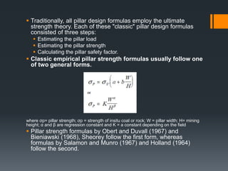
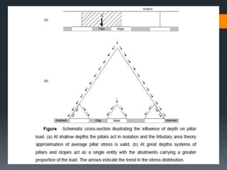
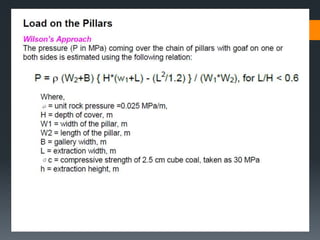
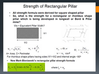
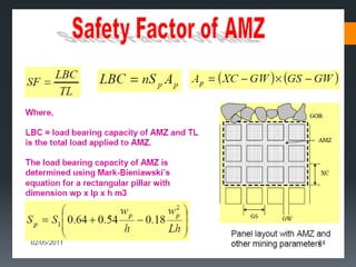
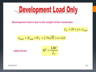
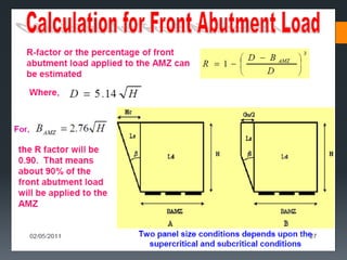
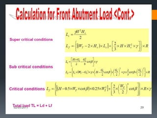
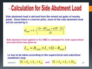
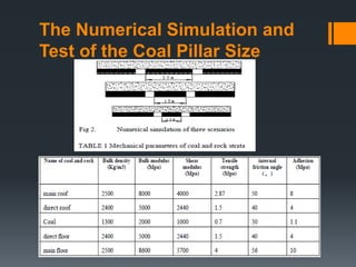
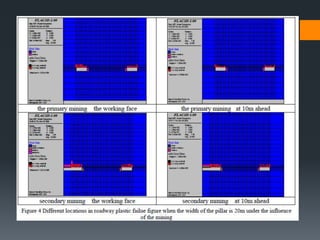
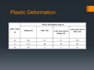
www.MINEPORTAL.in
ONLINE TEST SERIES FOR
 DGMS COAL/METAL FIRST/SECOND CLASS EXAM
 GATE MINING EXAM
 OVERMAN EXAM TEST
 MINING INSPECTOR EXAMS
 COAL INDIA MTs & OTHER PSUs EXAMS
FREE STUDY MATERIAL & VIDEO LECTURES
MINING JOBS NOTIFICATIONS
www.mineportal.in Call/Whatsapp-8804777500
www.fb.com/mineportal.in
Computer application in
pillar design
Coal Pillars Design Approaches:
 Ultimate Strength: The design determines the strength of a
pillar on the basis of its geometry, size and the compressive
strength of the material.
This approach will compare the expected load of the
pillar to its ultimate strength to determine its safety factor
value.
The main assumption of this approach is that, once the
ultimate strength is overcome the pillar will have zero
strength, which is not strictly true in reality.
 Progressive Failure: The design assumes a non-uniform
stress distribution within the pillar.
The failure of a pillar begin at the point of ultimate strength, and
gradually progresses to ultimate failure.
Wilson Core Model
Diest Strain Softening Model
 Numerical Models can adopt both ultimate strength and
progressive failure approaches.
 Traditionally, all pillar design formulas employ the ultimate
strength theory. Each of these "classic" pillar design formulas
consisted of three steps:
 Estimating the pillar load
 Estimating the pillar strength
 Calculating the pillar safety factor.
 Classic empirical pillar strength formulas usually follow one
of two general forms.
where σp= pillar strength; σp = strength of insitu coal or rock; W = pillar width; H= mining
height; α and β are regression constant and K = a constant depending on the field
 Pillar strength formulas by Obert and Duvall (1967) and
Bieniawski (1968), Sheorey follow the first form, whereas
formulas by Salamon and Munro (1967) and Holland (1964)
follow the second.
Pillar Loading
 Estimation of loading on the pillar of Bord and Pillar
mines based on tributary area loading concept.
Stress in pillar by Tributary area
method
The Numerical Simulation and
Test of the Coal Pillar Size
Plastic Deformation
Vertical stress distribution at different position in the pillar under the
influence by the mining when the pillar width is 20m
PLASTIC ZONE SIZE UNDER
DIFFERENT PILLAR WIDTH AND
REASONABLE PILLAR WIDTH
Prepared by-
11108EN023 – 11108EN032

Pillar design

  • 1.
    www.MINEPORTAL.in ONLINE TEST SERIESFOR  DGMS COAL/METAL FIRST/SECOND CLASS EXAM  GATE MINING EXAM  OVERMAN EXAM TEST  MINING INSPECTOR EXAMS  COAL INDIA MTs & OTHER PSUs EXAMS FREE STUDY MATERIAL & VIDEO LECTURES MINING JOBS NOTIFICATIONS www.mineportal.in Call/Whatsapp-8804777500 www.fb.com/mineportal.in
  • 2.
  • 3.
    Coal Pillars DesignApproaches:  Ultimate Strength: The design determines the strength of a pillar on the basis of its geometry, size and the compressive strength of the material. This approach will compare the expected load of the pillar to its ultimate strength to determine its safety factor value. The main assumption of this approach is that, once the ultimate strength is overcome the pillar will have zero strength, which is not strictly true in reality.  Progressive Failure: The design assumes a non-uniform stress distribution within the pillar. The failure of a pillar begin at the point of ultimate strength, and gradually progresses to ultimate failure. Wilson Core Model Diest Strain Softening Model  Numerical Models can adopt both ultimate strength and progressive failure approaches.
  • 4.
     Traditionally, allpillar design formulas employ the ultimate strength theory. Each of these "classic" pillar design formulas consisted of three steps:  Estimating the pillar load  Estimating the pillar strength  Calculating the pillar safety factor.  Classic empirical pillar strength formulas usually follow one of two general forms. where σp= pillar strength; σp = strength of insitu coal or rock; W = pillar width; H= mining height; α and β are regression constant and K = a constant depending on the field  Pillar strength formulas by Obert and Duvall (1967) and Bieniawski (1968), Sheorey follow the first form, whereas formulas by Salamon and Munro (1967) and Holland (1964) follow the second.
  • 5.
    Pillar Loading  Estimationof loading on the pillar of Bord and Pillar mines based on tributary area loading concept.
  • 6.
    Stress in pillarby Tributary area method
  • 26.
    The Numerical Simulationand Test of the Coal Pillar Size
  • 28.
  • 29.
    Vertical stress distributionat different position in the pillar under the influence by the mining when the pillar width is 20m
  • 30.
    PLASTIC ZONE SIZEUNDER DIFFERENT PILLAR WIDTH AND REASONABLE PILLAR WIDTH
  • 31.