Download as PDF, PPTX


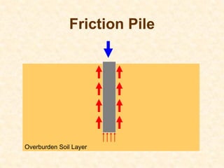
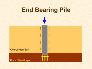


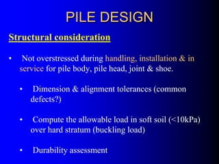
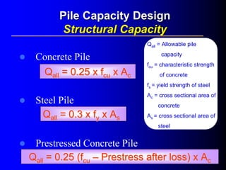
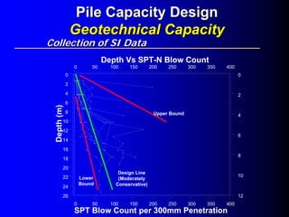
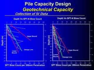


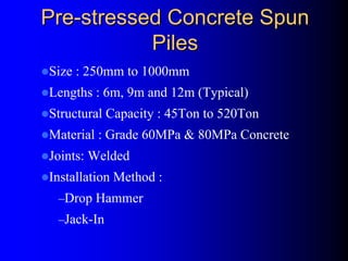
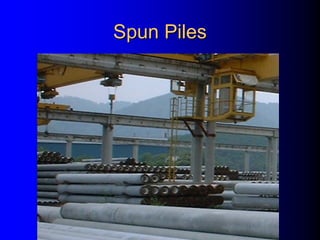
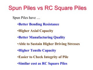
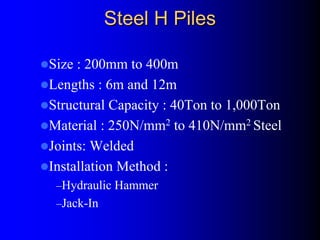


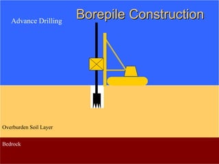
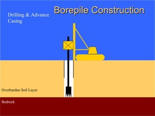
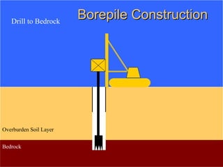
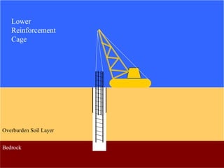


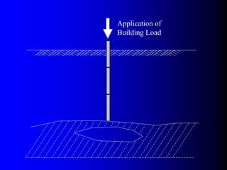
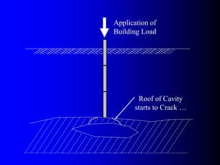
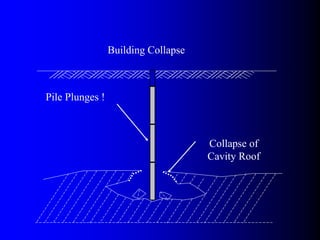
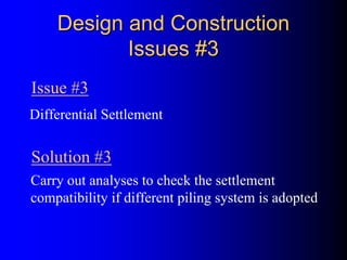


The document discusses the design and construction of pile foundations, highlighting their purpose, classification, and design criteria. It covers various types of piles, their installation methods, site investigation planning, and factors influencing pile selection. The document also delves into design considerations, allowable pile capacities, and factors of safety necessary for successful implementation of piling systems.


![Geotechnical Engineering-II [Lec #28: Finite Slope Stability Analysis]](https://cdn.slidesharecdn.com/ss_thumbnails/28-181125070402-thumbnail.jpg?width=640&height=640&fit=bounds)


