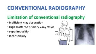
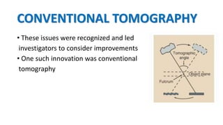
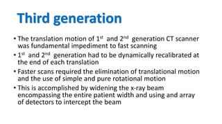
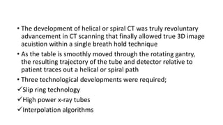
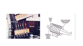
1. CT scanning has progressed through several generations from conventional to computed tomography. 2. First generation CT scanners used a translate-rotate motion and were slow, taking 5 minutes to complete an image. 3. Later generations incorporated faster rotating gantry systems and multi-detector arrays for faster acquisition times, with current scanners able to image in under 1 second. 4. The introduction of helical or spiral CT scanning allowed for true 3D imaging within a single breath hold.


![X-RAY FILM PROCESSING [Autosavee/d].pptx](https://cdn.slidesharecdn.com/ss_thumbnails/x-rayfilmprocessingautosaved-240224053318-4459007d-thumbnail.jpg?width=640&height=640&fit=bounds)


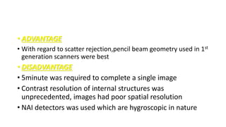
![Radiography of skull [Autosaved].pptxriuyowioehgg](https://cdn.slidesharecdn.com/ss_thumbnails/radiographyofskullautosaved-251211014507-1d75cfe3-thumbnail.jpg?width=640&height=640&fit=bounds)


