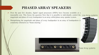
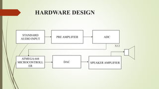
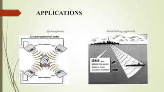
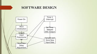
PHASED ARRAY SPEAKER SYSTEM
By,
RajaRaman.G
PHASED ARRAY SPEAKERS
 Over the past few decades, digital signal processors (DSPs) have become available at a
reasonable cost. This forces the question Now that it is possible to individually control the
magnitude and phase of every loudspeaker in an array called phase array speaker system.
 Manipulating the magnitude and phase of every loudspeaker in an array of loudspeakers is
commonly referred to as “beam steering.”
Line Array systems
Phase Array systems
OBJECTIVE
 The aim of the phased array speakers is to provide the maximum sound coverage over an entire area along
with best sound clarity. The voices and the sound effects could be more easily differentiated. This system is
comparatively cheaper when compared with its counterparts.
INTRODUCTION
 A phased array speaker system to generate flexible, directional sound.
 The system samples a standard audio input signal at approximately 44.1 kHz,
and then outputs this signal to each of 6-12 speakers, each with a variable delay.
 This simple technique allows audio frequency sound to be heard in only selected
regions within the room or other auditory space.
 Multiple regions with multiple soundtracks can be created by simultaneously
playing variously delayed soundtracks over each of the speakers in the array.
Sound waves from different loudspeakers can both combine or cancel depending
on the relative phase relationships between the sound waves, it is possible to
manipulate the phase (and magnitude) of the sound from two or more
loudspeakers to control where the sound cancels and where the sound sums.
EMERGING OF DIRECTIONAL SOUND
HARDWARE DESIGN
X12
STANDARD
AUDIO INPUT
PRE AMPLIFIER AADC
ATMEGA 644
MICROCONTROLL
ER
DAC SPEAKER AMPLIFIER
MODULES USED
 Standard audio input
 Pre Amplifier Block
 ADC
 ATMEGA 644 Microcontroller
 DAC
 Speaker Amplifier
 Speaker
APPLICATIONS
Quadraphonic Sonar testing apparatus
SOFTWARE USED
 WinAVR used for programming the microcontroller.
 EAGLE software to design circuits for fabrication.
SOFTWARE DESIGN
Power On
Sample
input
Potentiome
ter
Store New
Delay
Adjustment
MCU
initialization
Sample and
Store New
Input Data
Set Time-
delayed
DAC Output
Timer 1
Interrupt
PRE AMPLIFIER CIRCUIT
 Corner frequency of this input high pass
filter
1/(RC)= 1/(.1u*80k)
=125Hz.
 The amplification factor is
1+(R1/R2)=1+(200k/150k)
=2.33
DESCRIPTION
 The first stage is a high pass filter and re-biasing circuit, implemented by the first capacitor
and the resistor divider.
 The second stage of the input amplifier is implemented with an LF353P Op-Amp in a non-
inverting amplifier.
 It amplifies only the high frequency components due to the capacitor between the lower
resistor and ground.
 Voltage swing from -1V to +1V to be converted to -2.33V to +2.33V finally it will be
almost double to 5v.
PRE AMPLIFER TESTING
ADC
 ADC is used to sample input audio signal.
 It takes 10 cycles to transmit the 8 bits of data.
ALGORITHM
Initialization of microcontroller.
Declaration of buffers.
Setting up of timer and ADC.
Discrete audio signals are delayed with appropriate
coding and o/p is sent to respective i/p pins of
DAC.
MICROCONTROLLER
 The microcontroller used in this setup is the AT-mega 644.
 The microcontroller must have at least 13 I/O pins,
1 ADC input, and SPI capabilities.
 The crystal used in this setup should be 20MHz.
a) DEVELOPMENT BOARD b) PIN CONFIGURATION
DAC
 The DAC we use here is a parallel DAC.
 This is used for a faster execution.
 DAC what we use here is more flexible
which works at the rate of 44.1 KHz.
SPEAKER AMPLIFIER
 For better amplification at end of circuit we make use of another amplifier to provide better output.
 A Butterworth filter was selected over
cascading two passive RC filters.
 An op-amp with a really high slew rate
may be necessary if the application is
dealing with frequencies above the
human range of hearing.
POST AMPLIFIER TESTING
PRE AMPLIFIER ON EAGLE
SOFTWARE
POST AMPLIFIER ON EAGLE
SOFTWARE
DAC ON EAGLE SOFTWARE
PCB LAYER IN DAC DESIGN
TOP LAYER BOTTOM LAYER DOUBLE LAYER
PCB LAYER IN DAC DESIGN
DRILL LAYER SILK SCREEN OVERALL DESIGN
PCB LAYER FOR POST AMPLIFIER
BOTTOM LAYER TOP LAYER SILK SCREEN
PCB LAYER FOR POST AMPLIFIER
DRILL LAYER OVERALL DESIGN
PCB LAYER FOR PRE AMPLIFIER
TOP LAYER BOTTOM LAYER SILK SCREEN LAYER
PCB LAYER FOR PRE AMPLIFIER
DRILL LAYER OVERALL DESIGN
MATLAB SIMULATIN OUTPUT
Without Delay 30ms Delay
SPEAKER ALIGNMENT
REFERENCES
 Paul Crilly, Richard Hartnett, Rosie Santrach, Carlos Palenzuela
Department of Engineering, Electrical Engineering, U.S. Coast
Guard Academy, New London “A Novel Approach to Teaching
Phased Array Antenna Systems”
 Joseph Spradley, "A Volumetric Electrically Scanned Two-
Dimensional Microwave Antenna Array," IRE National Convention
Record, Part I – Antennas and Propagation; Microwaves, New York:
The Institute of Radio Engineers, 1958, 204–212.
THANK YOU

PHASED ARRAY SPEAKER SYSTEM

  • 1.
    PHASED ARRAY SPEAKERSYSTEM By, RajaRaman.G
  • 2.
    PHASED ARRAY SPEAKERS Over the past few decades, digital signal processors (DSPs) have become available at a reasonable cost. This forces the question Now that it is possible to individually control the magnitude and phase of every loudspeaker in an array called phase array speaker system.  Manipulating the magnitude and phase of every loudspeaker in an array of loudspeakers is commonly referred to as “beam steering.” Line Array systems Phase Array systems
  • 3.
    OBJECTIVE  The aimof the phased array speakers is to provide the maximum sound coverage over an entire area along with best sound clarity. The voices and the sound effects could be more easily differentiated. This system is comparatively cheaper when compared with its counterparts.
  • 4.
    INTRODUCTION  A phasedarray speaker system to generate flexible, directional sound.  The system samples a standard audio input signal at approximately 44.1 kHz, and then outputs this signal to each of 6-12 speakers, each with a variable delay.  This simple technique allows audio frequency sound to be heard in only selected regions within the room or other auditory space.  Multiple regions with multiple soundtracks can be created by simultaneously playing variously delayed soundtracks over each of the speakers in the array. Sound waves from different loudspeakers can both combine or cancel depending on the relative phase relationships between the sound waves, it is possible to manipulate the phase (and magnitude) of the sound from two or more loudspeakers to control where the sound cancels and where the sound sums.
  • 5.
  • 6.
    HARDWARE DESIGN X12 STANDARD AUDIO INPUT PREAMPLIFIER AADC ATMEGA 644 MICROCONTROLL ER DAC SPEAKER AMPLIFIER
  • 7.
    MODULES USED  Standardaudio input  Pre Amplifier Block  ADC  ATMEGA 644 Microcontroller  DAC  Speaker Amplifier  Speaker
  • 8.
  • 9.
    SOFTWARE USED  WinAVRused for programming the microcontroller.  EAGLE software to design circuits for fabrication.
  • 10.
    SOFTWARE DESIGN Power On Sample input Potentiome ter StoreNew Delay Adjustment MCU initialization Sample and Store New Input Data Set Time- delayed DAC Output Timer 1 Interrupt
  • 11.
    PRE AMPLIFIER CIRCUIT Corner frequency of this input high pass filter 1/(RC)= 1/(.1u*80k) =125Hz.  The amplification factor is 1+(R1/R2)=1+(200k/150k) =2.33
  • 12.
    DESCRIPTION  The firststage is a high pass filter and re-biasing circuit, implemented by the first capacitor and the resistor divider.  The second stage of the input amplifier is implemented with an LF353P Op-Amp in a non- inverting amplifier.  It amplifies only the high frequency components due to the capacitor between the lower resistor and ground.  Voltage swing from -1V to +1V to be converted to -2.33V to +2.33V finally it will be almost double to 5v.
  • 13.
  • 14.
    ADC  ADC isused to sample input audio signal.  It takes 10 cycles to transmit the 8 bits of data.
  • 15.
    ALGORITHM Initialization of microcontroller. Declarationof buffers. Setting up of timer and ADC. Discrete audio signals are delayed with appropriate coding and o/p is sent to respective i/p pins of DAC.
  • 16.
    MICROCONTROLLER  The microcontrollerused in this setup is the AT-mega 644.  The microcontroller must have at least 13 I/O pins, 1 ADC input, and SPI capabilities.  The crystal used in this setup should be 20MHz. a) DEVELOPMENT BOARD b) PIN CONFIGURATION
  • 17.
    DAC  The DACwe use here is a parallel DAC.  This is used for a faster execution.  DAC what we use here is more flexible which works at the rate of 44.1 KHz.
  • 18.
    SPEAKER AMPLIFIER  Forbetter amplification at end of circuit we make use of another amplifier to provide better output.  A Butterworth filter was selected over cascading two passive RC filters.  An op-amp with a really high slew rate may be necessary if the application is dealing with frequencies above the human range of hearing.
  • 19.
  • 20.
    PRE AMPLIFIER ONEAGLE SOFTWARE
  • 21.
    POST AMPLIFIER ONEAGLE SOFTWARE
  • 22.
    DAC ON EAGLESOFTWARE
  • 23.
    PCB LAYER INDAC DESIGN TOP LAYER BOTTOM LAYER DOUBLE LAYER
  • 24.
    PCB LAYER INDAC DESIGN DRILL LAYER SILK SCREEN OVERALL DESIGN
  • 25.
    PCB LAYER FORPOST AMPLIFIER BOTTOM LAYER TOP LAYER SILK SCREEN
  • 26.
    PCB LAYER FORPOST AMPLIFIER DRILL LAYER OVERALL DESIGN
  • 27.
    PCB LAYER FORPRE AMPLIFIER TOP LAYER BOTTOM LAYER SILK SCREEN LAYER
  • 28.
    PCB LAYER FORPRE AMPLIFIER DRILL LAYER OVERALL DESIGN
  • 29.
  • 30.
  • 31.
    REFERENCES  Paul Crilly,Richard Hartnett, Rosie Santrach, Carlos Palenzuela Department of Engineering, Electrical Engineering, U.S. Coast Guard Academy, New London “A Novel Approach to Teaching Phased Array Antenna Systems”  Joseph Spradley, "A Volumetric Electrically Scanned Two- Dimensional Microwave Antenna Array," IRE National Convention Record, Part I – Antennas and Propagation; Microwaves, New York: The Institute of Radio Engineers, 1958, 204–212.
  • 32.