The PCI Design Handbook 8th Edition, published in 2017, includes significant updates from the 7th edition, focusing on design, fabrication, and construction of precast and prestressed concrete products. It provides new design concepts, revised standards, and extensive updates across multiple chapters, including applications, analysis and design, materials, fire resistance, and more. This edition features new research, enhanced design aids, and comprehensive examples to guide industry professionals.


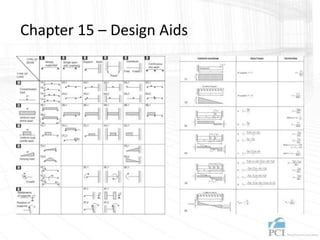
![Chapter 15 – Design Aids
• Design Information (loads, equations, and diagrams)
• Material Properties – Prestressing Steel
• Material Properties – Reinforcing Bars
• Material Properties – Welded-Wire Reinforcement
• Standard, Bolts, Nuts, and Washers
• Welding Information
• Section Properties
• Metric Conversion
• [Quick and easy reference for licensing exams]](https://image.slidesharecdn.com/pcidesignhandbookcontentandupdates-240724063911-4f0993b5/85/PCI-Design-Handbook-Content-and-Updates-pptx-67-320.jpg)