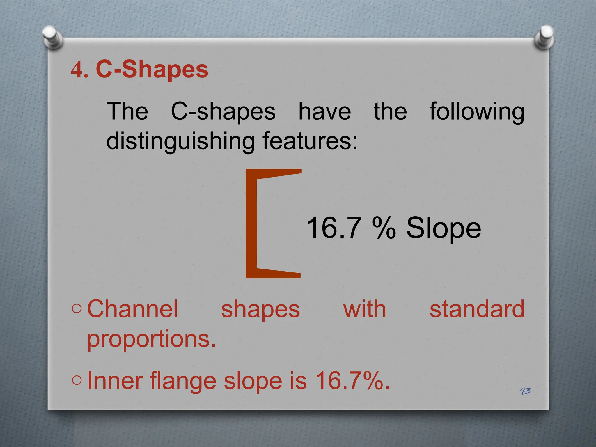
LOAD FACTORS AND LOAD
COMBINATION
It is impossible that all loads like live load,
wind load and earthquake all occur
together with their maximum intensity.
A load combination combines different
types of loads depending on the
probability of occurrence of these loads,
considering their expected intensity in the
combination compared with the maximum
load intensity.
1
The factors of safety are also included in
the LRFD load combinations and hence
the output of the expressions is a design
load.
The alphabets used in the combinations
mean different types of nominal service
loads and the numerical values with
them are all the load factors. 2
When intermediate floors have full
live loads, any type of roof load
may be considered equal to half
of its normal service load intensity.
Similarly, in case of maximum
intensity wind storm, live load may
be half.
3
The last combination, given afterwards, is
very important for uplift of structure or
reversal of forces.
The wind load on roof is upwards in
majority of the cases and if the downward
gravity load is less, the structure may be
blown up or sagging bending may change
into hogging bending.
A list of most commonly used
combinations are as under:
4
LRFD Load Combination
1. 1.4 (D+F)
2. 1.2 (D+F+T) + 1.6(L+H) +0.5(Lr or S or R)
3. 1.2D + 1.6(Lr or S or R) + (L or 0.8W)
4. 1.2D + 1.6W + 1.0L +0.5(Lr or S or R)
5. 1.2D + 1.0E + 1.0L + 0.2S
6. 0.9D + 1.6W + 1.6H
7. 0.9D + 1.0E + 1.6H
5
LRFD Load Combination
 D dead load
 L live load
 Lr roof live load
 W wind load
 S snow load
 E earthquake load
 R rainwater or ice load
 H load due to lateral earth pressure, ground
water pressure or pressure of bulk materials
 F load due to fluids with well defined
pressures and max heights.
 T self-retaining force
6
LRFD Load Combination
 Study the remaining discussion by yourself.
7
ASD Load Combination
1. D + F
2. D + H + F + L + T
3. D + H +F + (Lr or S or R)
4. D + H +F + 0.75(L + T) + 0.75 (Lr or S or R)
5. D + H +F + (W or 0.7E)
6. D + H +F + 0.75(W or 0.7E) + 0.75L + 0.75(Lr
or S or R)
7. 0.6D +W +H
8. 0.6D + 0.7E + H 8
Simplified Load Combinations
When the loads S, R, H, F, E and T are
taken equal to zero and wind loads are
taken from the previous codes, the load
combinations are reduced to the
following from:
9
LRFD
1. 1.4D
2. 1.2D + 1.6L + 0.5Lr
3. 1.2D + 1.6Lr + (L or 0.8W)
4. 1.2D + 1.3W + 1.0L + 0.5Lr
5. 0.9D + 1.3W
10
ASD
1. D
2. D + L
3. D + Lr
4. D + 0.75L + 0.75Lr
5. D + 0.8W
6. D + 0.6W + 0.75L + 0.75Lr
7. 0.6D + 0.8W 11
Live Load Reduction
The intensity of live load may be
reduced if the contributory area for
the live load exceeds certain limit.
It is due to the fact that, under these
circumstances, all the area may not
be subjected to the full load.
12
All uniform live loads, except the roof loads
(for which separate provisions are given in
ASCE-07), may be reduced as follows:
Where
Lo = the unreduced live load
AT = tributary area in m2
KLL = live load element factor
13










T
LL A
K
L
L
57
.
4
25
.
0

a Interior columns and exterior
columns without cantilever
slabs.
KLL = 4
b Edge columns with cantilever
slabs.
KLL = 3
c Corner columns with
cantilever slabs, edge beams
without cantilever slabs and
interior beams.
KLL = 2
d All other members including
slabs.
KLL = 1
14
TYPES OF STRUCTURAL STEEL
Steels are divided into four
categories depending on the
carbon percentages (C) as
following:
1. Low carbon steel C < 0.15%
2. Mild carbon steel C = 0.15 - 0.29%
3. Medium carbon steel C = 0.30 – 0.59%
4. High carbon steel C = 0.60 – 1.70%
15
E-Value of steel = 185 GPa to 230 GPa
(Average 200
GPa)
Unit weight = 7850 kg/m3
= 77 kN/m3
= 7.85 g/cc
For comparison, the unit weight of
concrete is 23.6 kN/m3
.
16
Most of the structural steel falls into
the mild carbon steel or simply mild
steel (MS) category.
Hot rolled structural shapes may be
made to conform to A36M, A529M,
A572M, A588M, A709M, A913M
and A992M.
17
Sheets are manufactured according
to the standards ASTM A606,
A1011MSS, HSLAS and HSLAS-F.
Bolts are made according to ASTM
standards A307, A325M, A449,
A40M and F1852.
18
Most commonly used structural
steel is A36M having the following
properties:
Fy = 250 MPa
Fu = 400 MPa
E = 200 GPa 19
Weld Electrode And Filler Material
Weld electrodes are classified as E60,
E70, E80, E100 and E110.
The letter E denotes electrodes.
The two digits indicate the ultimate
tensile strength in ksi. The
corresponding SI equivalents are E425,
E495, E550, E690 and E760.
20
HOT ROLLED STRUCTURAL SHAPES
These are the steel cross-sectional
shapes that are hot rolled in the mills.
Some of these shapes are shown in next
slides, whereas, the steel bars, plates
and hollow sections are reproduced in
slides next to the above slides.
An HP h x w is a bearing pile section,
which is approximately h mm deep
weighing w kgs/m.
21
HOT ROLLED STRUCTURAL SHAPES
Bearing piles are made with the
regular W rolls but with thicker web to
provide better resistance to the impact
of pile driving.
HSS are hollow structural sections that
are prismatic square, rectangular or
round products of a pipe or tubing.
22
23
HOT ROLLED STRUCTURAL
SHAPES
Every hot rolled shape has its unique
standard designation, which not only
tells about the type of cross-sectional
shape but also about its size.
The details about some of the
common hot rolled shapes are given
in the next slides.
24
25
Slope ≈ 0°
W-Section
26
16.7% Slope
S-Section
27
Angle-Section
28
Channel-Section
16.7% Slope
29
Tee-Section
30
HP-Section
Thicker than flange
31
Pipe Section
32
Structural Tubing
33
Bars
34
Plates
1. W-Shapes
The letter ‘W’ stands for an I-shape
with wide flange. The cross-section is
doubly symmetric in the form of the
letter “I”. The width / depth ratio varies
from about 0.3 to 1.0.
The US Customary designation W 16
x 40 means that the nominal depth of
the section is 16 in and the weight per
unit length of the section is 40 lbs/ft.
35
1. W-Shapes
Nominal height is the rounded
off height to be used for
common use.
Actual depth of the section may
be in decimals and somewhat
different from this depth.
36
The equivalent SI designation W410
x 60 means that the W-section has a
nominal depth of 410 mm and a
weight of 60 kgf/m. 37
Less or no slope Flange
Web
This kilogram-force weight per
unit length may be converted in
kN/m by multiplying it with the
factor 9.81/1000.
38
2. S-Shapes
o Doubly symmetrical I-shapes.
o Previously called standard I-beams or
American Standard Beam.
39
16.7% Slope
2. S-Shapes
o The inner edge of the flange has a slope
of approximately 16.7%.
o An S510 x 112 section means that the
section is S-shape having nominal depth
of 510 mm and weight of 112 kgf/m.
40
16.7 % Slope
2. S-Shapes
oThe width / depth ratio varies
from about 0.25 to 0.85.
41
16.7 % Slope
3. M-Shapes
o Miscellaneous I-shapes.
o Doubly symmetrical I-shapes not
classified as W or S shapes.
o Relatively lightweight used for smaller
spans and lesser loads.
o An M310 x 17.6 means that it is M-
shape section having nominal depth of
310 mm and weight of 17.6 kgf/m. 42
4. C-Shapes
The C-shapes have the following
distinguishing features:
o Channel shapes with standard
proportions.
o Inner flange slope is 16.7%. 43
16.7 % Slope
4. C-Shapes
The C-shapes have the following
distinguishing features:
O Previously called Standard or
American Standard Channels. 44
16.7 % Slope
4. C-Shapes
The C-shapes have the following
distinguishing features:
o A C150 x 19.3 is a standard channel
shape with a nominal depth of 150mm
and a weight of 19.3 kgf/m. 45
16.7 % Slope
5. MC-Shapes
These sections have the
following properties:
oChannels not classified as C-
shapes.
oPreviously called Shipbuilding or
Miscellaneous Channels.
46
6. L-Shapes or Angle Sections
The various types of angle sections
are shown in Figure and their salient
features are given below:
O The single angle sections are in the
form of letter ‘L’. 47
a
b
6. L-Shapes or Angle Sections
The various types of angle sections
are shown in Figure and their
salient features are given below:
O If a = b, these are called equal
angle sections. 48
a
b
6. L-Shapes or Angle Sections
The various types of angle sections
are shown in Figure and their salient
features are given below:
o If a ≠ b, these are called unequal
angle sections. 49
a
b
6. L-Shapes or Angle Sections
o Sides of the angle are called ‘legs’ or
‘arms’.
o L89 x 76 x 12.7 is an unequal leg
angle with longer leg dimension of
89mm and shorter leg dimension of
76mm with a leg thickness of 12.7mm.
50
a
b
6. L-Shapes or Angle Sections
o Double angle sections are
combination of two angles with longer
or shorter sides close to each other.
o Double angle sections are denoted
by 2Ls.
51
a
b
6. L-Shapes or Angle Sections
o2L89 x 76 x 12.7 means two
angles L89 x 76 x 12.7 placed side
by side in one of the ways shown
in the figure. 52
a
b
7. T-Shapes
o These are called structural tees.
o These are obtained by splitting W, S
or M shapes and are called WT, ST,
or MT shapes, respectively.
53
7. T-Shapes
o A WT205 x 30 is a structural tee
with a nominal depth of 205mm and
a weight of 30kgf/m and is obtained
by splitting the W410 x 60 section.
54
COLD – FORMED SHAPES
These sections are formed from
thin high strength steel alloy
plates under normal temperature.
Some of the common shapes of
these sections are drawn in
Figure:
55
56
Channels
57
Zees
58
I-Shaped Double Channels
59
Angle
60
Hat Sections
BUILT-UP SECTIONS
Sections made by combining two or
more standard hot rolled sections,
joined together at intervals with the
help of direct welding, stay plates or
lacing, are called built-up sections.
Examples are four angles section,
double angle section and double
channel section shown in Figure. 61
BUILT-UP SECTIONS
However, double angle section
is sometimes excluded from
built-up section category and is
considered as a regular hot
rolled member because of
difference of its behavior from
other built-up sections. 62
63
4-Angle Box Section
64
Double Angle
65
Two Channels connected back-to-back
66
Questions????
Thanks

203880851-Steel-sections-and-load-combinations.pptx

  • 1.
    LOAD FACTORS ANDLOAD COMBINATION It is impossible that all loads like live load, wind load and earthquake all occur together with their maximum intensity. A load combination combines different types of loads depending on the probability of occurrence of these loads, considering their expected intensity in the combination compared with the maximum load intensity. 1
  • 2.
    The factors ofsafety are also included in the LRFD load combinations and hence the output of the expressions is a design load. The alphabets used in the combinations mean different types of nominal service loads and the numerical values with them are all the load factors. 2
  • 3.
    When intermediate floorshave full live loads, any type of roof load may be considered equal to half of its normal service load intensity. Similarly, in case of maximum intensity wind storm, live load may be half. 3
  • 4.
    The last combination,given afterwards, is very important for uplift of structure or reversal of forces. The wind load on roof is upwards in majority of the cases and if the downward gravity load is less, the structure may be blown up or sagging bending may change into hogging bending. A list of most commonly used combinations are as under: 4
  • 5.
    LRFD Load Combination 1.1.4 (D+F) 2. 1.2 (D+F+T) + 1.6(L+H) +0.5(Lr or S or R) 3. 1.2D + 1.6(Lr or S or R) + (L or 0.8W) 4. 1.2D + 1.6W + 1.0L +0.5(Lr or S or R) 5. 1.2D + 1.0E + 1.0L + 0.2S 6. 0.9D + 1.6W + 1.6H 7. 0.9D + 1.0E + 1.6H 5
  • 6.
    LRFD Load Combination D dead load  L live load  Lr roof live load  W wind load  S snow load  E earthquake load  R rainwater or ice load  H load due to lateral earth pressure, ground water pressure or pressure of bulk materials  F load due to fluids with well defined pressures and max heights.  T self-retaining force 6
  • 7.
    LRFD Load Combination Study the remaining discussion by yourself. 7
  • 8.
    ASD Load Combination 1.D + F 2. D + H + F + L + T 3. D + H +F + (Lr or S or R) 4. D + H +F + 0.75(L + T) + 0.75 (Lr or S or R) 5. D + H +F + (W or 0.7E) 6. D + H +F + 0.75(W or 0.7E) + 0.75L + 0.75(Lr or S or R) 7. 0.6D +W +H 8. 0.6D + 0.7E + H 8
  • 9.
    Simplified Load Combinations Whenthe loads S, R, H, F, E and T are taken equal to zero and wind loads are taken from the previous codes, the load combinations are reduced to the following from: 9
  • 10.
    LRFD 1. 1.4D 2. 1.2D+ 1.6L + 0.5Lr 3. 1.2D + 1.6Lr + (L or 0.8W) 4. 1.2D + 1.3W + 1.0L + 0.5Lr 5. 0.9D + 1.3W 10
  • 11.
    ASD 1. D 2. D+ L 3. D + Lr 4. D + 0.75L + 0.75Lr 5. D + 0.8W 6. D + 0.6W + 0.75L + 0.75Lr 7. 0.6D + 0.8W 11
  • 12.
    Live Load Reduction Theintensity of live load may be reduced if the contributory area for the live load exceeds certain limit. It is due to the fact that, under these circumstances, all the area may not be subjected to the full load. 12
  • 13.
    All uniform liveloads, except the roof loads (for which separate provisions are given in ASCE-07), may be reduced as follows: Where Lo = the unreduced live load AT = tributary area in m2 KLL = live load element factor 13           T LL A K L L 57 . 4 25 . 0 
  • 14.
    a Interior columnsand exterior columns without cantilever slabs. KLL = 4 b Edge columns with cantilever slabs. KLL = 3 c Corner columns with cantilever slabs, edge beams without cantilever slabs and interior beams. KLL = 2 d All other members including slabs. KLL = 1 14
  • 15.
    TYPES OF STRUCTURALSTEEL Steels are divided into four categories depending on the carbon percentages (C) as following: 1. Low carbon steel C < 0.15% 2. Mild carbon steel C = 0.15 - 0.29% 3. Medium carbon steel C = 0.30 – 0.59% 4. High carbon steel C = 0.60 – 1.70% 15
  • 16.
    E-Value of steel= 185 GPa to 230 GPa (Average 200 GPa) Unit weight = 7850 kg/m3 = 77 kN/m3 = 7.85 g/cc For comparison, the unit weight of concrete is 23.6 kN/m3 . 16
  • 17.
    Most of thestructural steel falls into the mild carbon steel or simply mild steel (MS) category. Hot rolled structural shapes may be made to conform to A36M, A529M, A572M, A588M, A709M, A913M and A992M. 17
  • 18.
    Sheets are manufacturedaccording to the standards ASTM A606, A1011MSS, HSLAS and HSLAS-F. Bolts are made according to ASTM standards A307, A325M, A449, A40M and F1852. 18
  • 19.
    Most commonly usedstructural steel is A36M having the following properties: Fy = 250 MPa Fu = 400 MPa E = 200 GPa 19
  • 20.
    Weld Electrode AndFiller Material Weld electrodes are classified as E60, E70, E80, E100 and E110. The letter E denotes electrodes. The two digits indicate the ultimate tensile strength in ksi. The corresponding SI equivalents are E425, E495, E550, E690 and E760. 20
  • 21.
    HOT ROLLED STRUCTURALSHAPES These are the steel cross-sectional shapes that are hot rolled in the mills. Some of these shapes are shown in next slides, whereas, the steel bars, plates and hollow sections are reproduced in slides next to the above slides. An HP h x w is a bearing pile section, which is approximately h mm deep weighing w kgs/m. 21
  • 22.
    HOT ROLLED STRUCTURALSHAPES Bearing piles are made with the regular W rolls but with thicker web to provide better resistance to the impact of pile driving. HSS are hollow structural sections that are prismatic square, rectangular or round products of a pipe or tubing. 22
  • 23.
  • 24.
    HOT ROLLED STRUCTURAL SHAPES Everyhot rolled shape has its unique standard designation, which not only tells about the type of cross-sectional shape but also about its size. The details about some of the common hot rolled shapes are given in the next slides. 24
  • 25.
  • 26.
  • 27.
  • 28.
  • 29.
  • 30.
  • 31.
  • 32.
  • 33.
  • 34.
  • 35.
    1. W-Shapes The letter‘W’ stands for an I-shape with wide flange. The cross-section is doubly symmetric in the form of the letter “I”. The width / depth ratio varies from about 0.3 to 1.0. The US Customary designation W 16 x 40 means that the nominal depth of the section is 16 in and the weight per unit length of the section is 40 lbs/ft. 35
  • 36.
    1. W-Shapes Nominal heightis the rounded off height to be used for common use. Actual depth of the section may be in decimals and somewhat different from this depth. 36
  • 37.
    The equivalent SIdesignation W410 x 60 means that the W-section has a nominal depth of 410 mm and a weight of 60 kgf/m. 37 Less or no slope Flange Web
  • 38.
    This kilogram-force weightper unit length may be converted in kN/m by multiplying it with the factor 9.81/1000. 38
  • 39.
    2. S-Shapes o Doublysymmetrical I-shapes. o Previously called standard I-beams or American Standard Beam. 39 16.7% Slope
  • 40.
    2. S-Shapes o Theinner edge of the flange has a slope of approximately 16.7%. o An S510 x 112 section means that the section is S-shape having nominal depth of 510 mm and weight of 112 kgf/m. 40 16.7 % Slope
  • 41.
    2. S-Shapes oThe width/ depth ratio varies from about 0.25 to 0.85. 41 16.7 % Slope
  • 42.
    3. M-Shapes o MiscellaneousI-shapes. o Doubly symmetrical I-shapes not classified as W or S shapes. o Relatively lightweight used for smaller spans and lesser loads. o An M310 x 17.6 means that it is M- shape section having nominal depth of 310 mm and weight of 17.6 kgf/m. 42
  • 43.
    4. C-Shapes The C-shapeshave the following distinguishing features: o Channel shapes with standard proportions. o Inner flange slope is 16.7%. 43 16.7 % Slope
  • 44.
    4. C-Shapes The C-shapeshave the following distinguishing features: O Previously called Standard or American Standard Channels. 44 16.7 % Slope
  • 45.
    4. C-Shapes The C-shapeshave the following distinguishing features: o A C150 x 19.3 is a standard channel shape with a nominal depth of 150mm and a weight of 19.3 kgf/m. 45 16.7 % Slope
  • 46.
    5. MC-Shapes These sectionshave the following properties: oChannels not classified as C- shapes. oPreviously called Shipbuilding or Miscellaneous Channels. 46
  • 47.
    6. L-Shapes orAngle Sections The various types of angle sections are shown in Figure and their salient features are given below: O The single angle sections are in the form of letter ‘L’. 47 a b
  • 48.
    6. L-Shapes orAngle Sections The various types of angle sections are shown in Figure and their salient features are given below: O If a = b, these are called equal angle sections. 48 a b
  • 49.
    6. L-Shapes orAngle Sections The various types of angle sections are shown in Figure and their salient features are given below: o If a ≠ b, these are called unequal angle sections. 49 a b
  • 50.
    6. L-Shapes orAngle Sections o Sides of the angle are called ‘legs’ or ‘arms’. o L89 x 76 x 12.7 is an unequal leg angle with longer leg dimension of 89mm and shorter leg dimension of 76mm with a leg thickness of 12.7mm. 50 a b
  • 51.
    6. L-Shapes orAngle Sections o Double angle sections are combination of two angles with longer or shorter sides close to each other. o Double angle sections are denoted by 2Ls. 51 a b
  • 52.
    6. L-Shapes orAngle Sections o2L89 x 76 x 12.7 means two angles L89 x 76 x 12.7 placed side by side in one of the ways shown in the figure. 52 a b
  • 53.
    7. T-Shapes o Theseare called structural tees. o These are obtained by splitting W, S or M shapes and are called WT, ST, or MT shapes, respectively. 53
  • 54.
    7. T-Shapes o AWT205 x 30 is a structural tee with a nominal depth of 205mm and a weight of 30kgf/m and is obtained by splitting the W410 x 60 section. 54
  • 55.
    COLD – FORMEDSHAPES These sections are formed from thin high strength steel alloy plates under normal temperature. Some of the common shapes of these sections are drawn in Figure: 55
  • 56.
  • 57.
  • 58.
  • 59.
  • 60.
  • 61.
    BUILT-UP SECTIONS Sections madeby combining two or more standard hot rolled sections, joined together at intervals with the help of direct welding, stay plates or lacing, are called built-up sections. Examples are four angles section, double angle section and double channel section shown in Figure. 61
  • 62.
    BUILT-UP SECTIONS However, doubleangle section is sometimes excluded from built-up section category and is considered as a regular hot rolled member because of difference of its behavior from other built-up sections. 62
  • 63.
  • 64.
  • 65.
  • 66.