Download to read offline


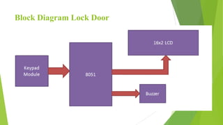


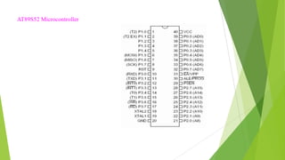


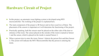


This presentation summarizes a student project that developed a digital door lock system and automatic room light controlling system using a microcontroller. The system uses an AT89S52 microcontroller to control a keypad lock on a door and infrared sensors to detect movement and automatically turn lights on and off. The presentation describes the existing manual systems, components used, circuit designs, applications, and plans to add voice password and control additional devices like fans.