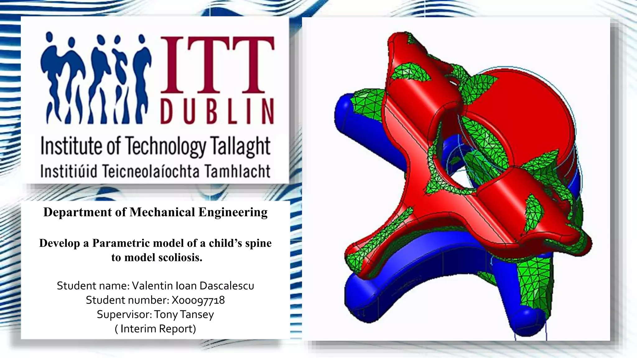
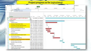
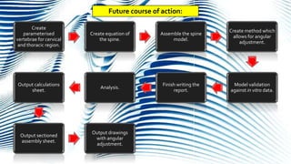
Department of Mechanical Engineering
Develop a Parametric model of a child’s spine
to model scoliosis.
Student name:Valentin Ioan Dascalescu
Student number: X00097718
Supervisor:TonyTansey
( Interim Report)
Introduction:
The main objective of this project is to
develop a parametric model
framework of the human spine based
on a command file system by
combining different modelling
technics with vertebra and spine
parameters which are deduced from
existing anthropometric data bases .
Secondary objective will be
completing a conclusive literature
review of relevant scientific journals
and peer reviewed papers that will,
provide a better understanding of the
project and, generate a guide for the
completion of it.
Project Objectives:
Literature review:
In vitro, in vivo
and in silico
methodologies.
Anatomy of the
spine.
Anatomy of the
vertebrae
Modelling
techniques.
Medical imaging
methods.
Existing models of
the human spine
and vertebra.
Anthropometric
data base.
Validation
• Obtaining vertebra dimensions from computer tomography (CT) scans.
• A precise segmentation of a full vertebra from a CT scan is a challenging process and it is affected by various factors
such as: complex anatomical structure, unclear object boundaries, similar structures in near vicinity and degenerative
deformities
• (images: Akyokus, Meram, Konya, Turkey : Journal of Craniovertebral Junction&Spine, 2015, Vol. 6. )
Modelling the Scoliotic spine:
Modelling from stereo lithography (STL) type file:
Based on the knowledge obtained from the literature review, it was decided to model the geometry of the
parametric vertebrae from STL files using primitives such as: circles, ellipses and cylinders. The resulting
models are very close approximation of the vertebrae.
STL
file
Solid
model
Parameterization
Process of the
vertebrae in PTC Creo
1.Vertebra height is obtained
from subtracting the hip
height from the shoulder
height and dividing by the
number of vertebrae. Data is
selected from
http://dined.io.tudelft.nl/en
2. Using Panjabi et all
1911,1992 data sets,
together with published
data, the main parameters of
the vertebrae are identified.
3. Using assumptions and
critical parameters the
correlating relations between
the main vertebra regions are
formulated.
4. New parametric
vertebrae are generated.
They have a direct linear
relation to the master
vertebra model.
Picture of the vertebra
here
Geometry control by parameterisation
Parameterisation of the master vertebrae:
• When using a CAD type software, a
geometry entity can be defined by
dimensions.
• In parametric modelling is the dimensions
that drive, define, the geometry.
• The advantage is that, once the key
elements of a geometry entity are captured
in the drawing, they could all be related to
each other or to a driving parameter, so that
later on, the geometry could by altered or
modified by changing that respective
parameter
• http://dined.io.tudelft.nl/en/database/intr
oduction.
• The most in-depth and complete resource
of data is provided by the Panjabi et all
• “Thoracic Human Vertabrae-
Quantitative 3-Dimensional Anatomy,.
Spine. August, 1991,Vol. 16.”
Parameters and relations:
Nomenclature of vertebra defining parameters
Spine Deformity. November, 2013,Vol. 1, 6.
Parameters prediction formulae (M. Haghpanahi, M. Javadi,.
December, Narmak Ave., Tehran, Iran : Science Direct, 2011. )
Panjabi et all Spine 1992
Data collection
Datasets were compiled by direct measuring and by statistical analysis such as linear regression, mean and standard deviation
Lengths of the thoracic, lumbar and combined spine lengths by age with minimums and maximums
(Normal growth of the spine and skeletal maturation, Seminars in spine surgery 2015).
Project progress so far (15/12/2015)
Future course of action:
Create
parameterised
vertebrae for cervical
and thoracic region.
Create equation of
the spine.
Assemble the spine
model.
Create method which
allows for angular
adjustment.
Model validation
against in vitro data.
Finish writing the
report.
Analysis.
Output calculations
sheet.
Output sectioned
assembly sheet.
Output drawings
with angular
adjustment.
Thank you for your attention! Any questions ?

Parametric Human spine.

  • 1.
    Department of MechanicalEngineering Develop a Parametric model of a child’s spine to model scoliosis. Student name:Valentin Ioan Dascalescu Student number: X00097718 Supervisor:TonyTansey ( Interim Report)
  • 2.
  • 3.
    The main objectiveof this project is to develop a parametric model framework of the human spine based on a command file system by combining different modelling technics with vertebra and spine parameters which are deduced from existing anthropometric data bases . Secondary objective will be completing a conclusive literature review of relevant scientific journals and peer reviewed papers that will, provide a better understanding of the project and, generate a guide for the completion of it. Project Objectives:
  • 4.
    Literature review: In vitro,in vivo and in silico methodologies. Anatomy of the spine. Anatomy of the vertebrae Modelling techniques. Medical imaging methods. Existing models of the human spine and vertebra. Anthropometric data base. Validation
  • 5.
    • Obtaining vertebradimensions from computer tomography (CT) scans. • A precise segmentation of a full vertebra from a CT scan is a challenging process and it is affected by various factors such as: complex anatomical structure, unclear object boundaries, similar structures in near vicinity and degenerative deformities • (images: Akyokus, Meram, Konya, Turkey : Journal of Craniovertebral Junction&Spine, 2015, Vol. 6. ) Modelling the Scoliotic spine:
  • 6.
    Modelling from stereolithography (STL) type file: Based on the knowledge obtained from the literature review, it was decided to model the geometry of the parametric vertebrae from STL files using primitives such as: circles, ellipses and cylinders. The resulting models are very close approximation of the vertebrae. STL file Solid model
  • 7.
    Parameterization Process of the vertebraein PTC Creo 1.Vertebra height is obtained from subtracting the hip height from the shoulder height and dividing by the number of vertebrae. Data is selected from http://dined.io.tudelft.nl/en 2. Using Panjabi et all 1911,1992 data sets, together with published data, the main parameters of the vertebrae are identified. 3. Using assumptions and critical parameters the correlating relations between the main vertebra regions are formulated. 4. New parametric vertebrae are generated. They have a direct linear relation to the master vertebra model. Picture of the vertebra here Geometry control by parameterisation
  • 8.
    Parameterisation of themaster vertebrae: • When using a CAD type software, a geometry entity can be defined by dimensions. • In parametric modelling is the dimensions that drive, define, the geometry. • The advantage is that, once the key elements of a geometry entity are captured in the drawing, they could all be related to each other or to a driving parameter, so that later on, the geometry could by altered or modified by changing that respective parameter • http://dined.io.tudelft.nl/en/database/intr oduction. • The most in-depth and complete resource of data is provided by the Panjabi et all • “Thoracic Human Vertabrae- Quantitative 3-Dimensional Anatomy,. Spine. August, 1991,Vol. 16.”
  • 9.
    Parameters and relations: Nomenclatureof vertebra defining parameters Spine Deformity. November, 2013,Vol. 1, 6. Parameters prediction formulae (M. Haghpanahi, M. Javadi,. December, Narmak Ave., Tehran, Iran : Science Direct, 2011. )
  • 10.
    Panjabi et allSpine 1992 Data collection Datasets were compiled by direct measuring and by statistical analysis such as linear regression, mean and standard deviation
  • 11.
    Lengths of thethoracic, lumbar and combined spine lengths by age with minimums and maximums (Normal growth of the spine and skeletal maturation, Seminars in spine surgery 2015).
  • 12.
    Project progress sofar (15/12/2015)
  • 13.
    Future course ofaction: Create parameterised vertebrae for cervical and thoracic region. Create equation of the spine. Assemble the spine model. Create method which allows for angular adjustment. Model validation against in vitro data. Finish writing the report. Analysis. Output calculations sheet. Output sectioned assembly sheet. Output drawings with angular adjustment.
  • 14.
    Thank you foryour attention! Any questions ?