

![Modeling Memory Interference
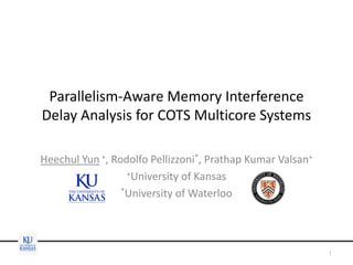
• Common (false) assumptions on COTS systems
– A single resource
• Reality: multiple parallel resources (banks)
– A constant memory service cost
• Reality: it varies depending on the DRAM bank state
– Round-robin arbitration, in-order processing
• Reality: FR-FCFS can re-order requests
– Both read and write requests are treated equally
• Reality: writes are buffered and processed opportunistically
– One outstanding request per core
• Reality: an out-of-order core can generate parallel reqs.
5
Addressed in This Work
Addressed in [Kim’14]
[Kim’14] H. Kim, D. de Niz, B. Andersson, M. Klein, O. Mutlu, and R. R.Rajkumar. “Bounding Memory Interference
Delay in COTS-based Multi-Core Systems,” RTAS’14](https://image.slidesharecdn.com/heechul-2015-ecrts-web-150726182933-lva1-app6891/85/Parallelism-Aware-Memory-Interference-Delay-Analysis-for-COTS-Multicore-Systems-5-320.jpg)


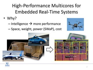
![“Intelligent” Read/Write Switching
• Intuition
– Writes are not in the critical path. So buffer and
process them opportunistically
• Algorithm [Hansson’14]
– If there are reads, process them unless the write
buffer is almost full (high watermark)
– If there’s no reads and there is enough buffered
writes (low watermark), process the writes until
reads arrive
14
[Hansson’14] Hansson et al., “Simulating DRAM controllers for future syste
m architecture exploration,” ISPASS’14](https://image.slidesharecdn.com/heechul-2015-ecrts-web-150726182933-lva1-app6891/85/Parallelism-Aware-Memory-Interference-Delay-Analysis-for-COTS-Multicore-Systems-14-320.jpg)
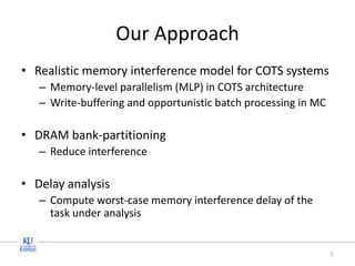
![FR-FCFS Scheduling[Rixner’00]
• Priority order
1. Row hit request
2. Older request
• Maximize memory throughput
15
Bank 1
scheduler
Channel scheduler
Bank 2
scheduler
Bank N
scheduler
[Rixner’00] S. Rixner, W. J. Dally, U. J. Kapasi, P. Mattson, and J. Owens. Memo
ry access scheduling. ACM SIGARCH Computer Architecture News. 2000](https://image.slidesharecdn.com/heechul-2015-ecrts-web-150726182933-lva1-app6891/85/Parallelism-Aware-Memory-Interference-Delay-Analysis-for-COTS-Multicore-Systems-15-320.jpg)


![Key Intuition #2
• DRAM sub-commands of the competing
memory requests are overlapped
– Much less pessimistic than [Kim’14], which simply
sums up each sub-command’s maximum delay
– See paper for the proof
20](https://image.slidesharecdn.com/heechul-2015-ecrts-web-150726182933-lva1-app6891/85/Parallelism-Aware-Memory-Interference-Delay-Analysis-for-COTS-Multicore-Systems-20-320.jpg)


![Evaluation Setup
• Gem5 simulator
– 4 out-of-order cores (based on Cortex-A15)
• L2 MSHR size is increased to eliminate MSHR contention
– DRAM controller model [Hansson’14]
– LPDDR2 @ 533Mhz
• Linux 3.14
– Use PALLOC[Yun’14] to partition
DRAM banks and LLC
• Workload
– Subject: Latency, SPEC2006
– Co-runners: Bandwidth (write)
23
DRAM
LLC
Core1 Core2 Core3 Core4
subject co-runner(s)](https://image.slidesharecdn.com/heechul-2015-ecrts-web-150726182933-lva1-app6891/85/Parallelism-Aware-Memory-Interference-Delay-Analysis-for-COTS-Multicore-Systems-23-320.jpg)
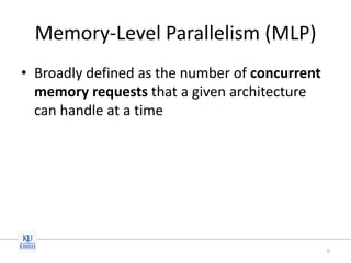
![Results with the Latency benchmark
• Ours(ideal): Read only delay analysis (ignore writes)
• Ours(opt): assume writes are balanced over multiple banks
• Ours(worst): all writes are targeting one bank & all row misses
24
0
5
10
15
20
25
30
Measured [Kim'14] Ours(ideal) Ours(opt) Ours(worst)
NormalizedResponseTime
underestimate
overestimate
[Kim’14] H. Kim, D. de Niz, B. Andersson, M. Klein, O. Mutlu, and R. R.Rajkumar. “Bounding Memory Interference
Delay in COTS-based Multi-Core Systems,” RTAS’14](https://image.slidesharecdn.com/heechul-2015-ecrts-web-150726182933-lva1-app6891/85/Parallelism-Aware-Memory-Interference-Delay-Analysis-for-COTS-Multicore-Systems-24-320.jpg)


The document discusses a new approach to analyze memory interference delays in commercial off-the-shelf (COTS) multicore systems, addressing challenges posed by shared memory and multiple parallel resources. It proposes a realistic memory interference model and emphasizes the importance of memory-level parallelism, bank partitioning, and an efficient scheduling algorithm in minimizing memory delays. The evaluation demonstrates that the proposed model can provide useful insights for low memory-intensive tasks while highlighting areas for further research to reduce pessimism in the analysis.