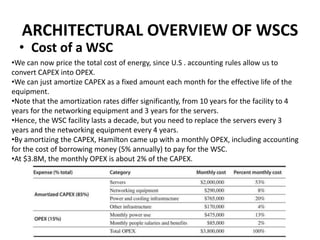
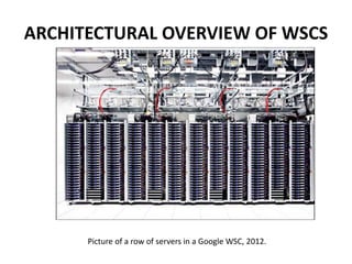
This document provides an overview of the architecture of warehouse-scale computers (WSCs). It describes how WSCs consist of large numbers of standardized servers organized in racks and arrays. The servers communicate over an Ethernet network hierarchy with switches at the rack and array level. This network architecture provides high aggregate bandwidth and storage capacity but also increases latency for remote memory access compared to local server memory. The document outlines the key components and networking design of WSCs.
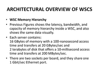
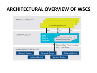
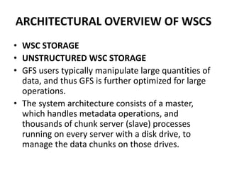
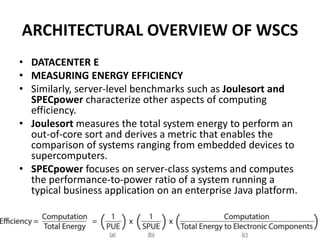
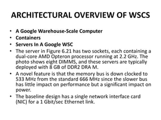
![ARCHITECTURAL OVERVIEW OF WSCS
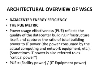
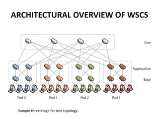
The Layer 3 network used to link arrays together and to the Internet
[Greenberg et al. 2009].
Some WSCs use a separate border router to connect the Internet to the
datacenter Layer 3 switches.](https://image.slidesharecdn.com/warehousescalecomputer-151203185707-lva1-app6891/85/Warehouse-scale-computer-29-320.jpg)
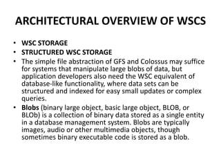
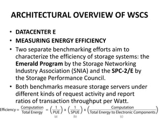
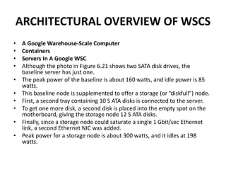
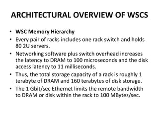
![ARCHITECTURAL OVERVIEW OF WSCS
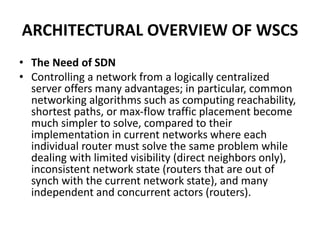
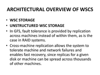
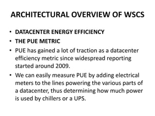
• The Need of SDN
• The need for a programmable network has led
to much interest in OpenFlow
[http://www.openflow.org/] and software-
defined networking (SDN), which moves the
network control plane out of the individual
switches into a logically centralized controller.](https://image.slidesharecdn.com/warehousescalecomputer-151203185707-lva1-app6891/85/Warehouse-scale-computer-35-320.jpg)