Download to read offline
![Hamza Kheddar Int. Journal of Engineering Research and Applications www.ijera.com
ISSN : 2248-9622, Vol. 5, Issue 3, ( Part -4) March 2015, pp.85-89
www.ijera.com 85 | P a g e
Implementation of Interleaving Methods on MELP 2.4 Coder to
Reduce Packet Loss in the Voice over IP (VoIP) Transmission
Hamza Kheddar*, Bachir Boudraa **
*(Department of Telecommunication, LCPTS Lab USTHB University, Algeria)
** (Department of Telecommunication, LCPTS Lab USTHB University, Algeria)
ABSTRACT
The work consists first of making improvements of a MELP coder running at 2.4 kbps by the implementation of
packets lost concealment techniques based on the receiver. These techniques consist of interleaving information
frames, then, we conducted a comparative study of several interlacing methods. For this, we used the evaluation
technique standardized by ITU-T called PESQ (Perceptual Evaluation of Speech Quality).
Keywords –VoIP Transmission, Interleaving, MELP Coding, PLC, PESQ.
I. INTRODUCTION
In a VoIP system, at the receiver, some packages
may be missing; this packet loss degrades the voice
quality and translates into ruptures of the
conversation and impression of hatching of speech. It
is therefore essential to establish a mechanism for
concealing the losses. Several algorithms masking
packet loss also called PLC (Packet Loss
Concealment) are used both at the transmitter and/or
the receiver.
Our work is to improve the MELP codec
operates at 2.4 Kbps by implementing concealment
techniques of lost frames based on the receiver.
These techniques consist of interleaving information
frames. We then conducted a comparative study of
the implemented methods. The comparative
assessment was made using a method called PESQ
(Perceptual Evaluation of Speech Quality).
II. MELP CODING
The MELP has now become the new military
and Federal standard for speech at 2.4 kbps, replacing
federal standards FS-1015 (LPC-10) and FS-1016
(CELP) speech that produce poor quality at this rate.
Implementing a MELP coder involves four steps:
analysis, encoding, decoding and synthesis [1] – [2].
A) MELP Encoder
In the synthesis MELP, LP (linear prediction)
all-pole filter is excited by a signal built from
periodic contributions and noise.
At the encoder (Fig.1), the LP parameters are
first determined. The residual is then obtained. The
pitch is estimated from the low-pass filtering of the
speech signal. The voicing strengths are evaluated
based on the correlation maxima of the band-pass
filtered signal. Voicing determines how the periodic
parts and noise contribute to the excitement of the LP
in specific frequency bands. Describe, in fact, the
presence of periodicity in the function of the
frequency signal. The Fourier coefficients define the
spectral characteristics of the periodic excitation of
LP. They are usually calculated from the FFT of the
signal. Determining the gain can be performed either
on the LP residual or directly on the speech signal,
synchronously or with a fixed length window [3].
Fig.1 Basic schema of MELP Encoder
B) MELP decoder
At the decoder (Fig.2), the periodic part of the
excitement is generated from the Fourier coefficients
interpolated. Fourier synthesis is applied to spectra in
which the Fourier coefficients are placed at the
harmonic frequencies derived from the interpolated
pitch. The sound of excitement is generated from
white noise. The frequency bands of the periodic part
of the signal and noise are shaped through time
domain filtering according to the transmitted voicing
information. The two components of the excitation
are added and the signal is scaled by the encoded
gain. Finally, the linear prediction synthesis is
performed [3].
Input speech
LP
residual
LP Parameters
Pitch
Analysis
Band-pass
Voicing
LP
Analysis
Gain
Analysis
Fourrier Coeff. Estimation
Gain
Voicing
Pitch
Fourrier
Coeff.
RESEARCH ARTICLE OPEN ACCESS](https://image.slidesharecdn.com/p503048589-150331065214-conversion-gate01/75/Implementation-of-Interleaving-Methods-on-MELP-2-4-Coder-to-Reduce-Packet-Loss-in-the-Voice-over-IP-VoIP-Transmission-1-2048.jpg)
![Hamza Kheddar Int. Journal of Engineering Research and Applications www.ijera.com
ISSN : 2248-9622, Vol. 5, Issue 3, ( Part -4) March 2015, pp.85-89
www.ijera.com 86 | P a g e
Fig.2 Basic schema of MELP Decoder.
III. INTERLEAVING
To achieve a voice in real-time high quality,
packet loss concealment mechanism must be put in
place. Several packet loss concealment algorithms
PLC (Packet Loss Concealment) are used either at
the transmitter or at the receiver [4]-[6].
Interlacing is an effective method to disperse packet
loss bursts into a series of small losses. As a result,
the errors will be produced on relatively short code
words and the listener will be able to mentally
interpolate small gaps. The intelligibility of speech is
then preserved.
A) Implementation of some interleaving
methods
1- Convolutional interleavers
A convolutional interleaver can be modeled as a
shift register arrangement, each having a
characteristic vector. In a convolutional interleaver of
degree 𝑑, the input vector sequence is divided into 𝑑
subsequences. Each sub-sequence consists of a
different number of connected shift registers, which
thus corresponds to a different delay according to the
number of feature vectors that are stored there [7]. A
convolutional interleaver of degree 4 is illustrated in
fig.3. A convolutional interleaver size N (𝑑 = 𝑁
subsequences) takes the form:
𝜋 𝑐𝑜𝑛𝑣 𝑖 = 𝑖 − 𝑑 𝑖 𝑚𝑜𝑑 𝑑 (1)
2- Decorrelated convolutional interleaver
The decorrelated convolutional interleaver
introduced the same decorrelated structure of the
convolutional interleaver described above. A
decorrelated convolutional interleaver is formed by
permuting the order in which the individual sub-
sequences are accessible. For a decorrelated
convolutional interleaver of size 𝑑, the order in which
the sub-sequences are accessible is defined by the
permutation 𝑃 of the length 𝑑 [7]. For example, a
decorrelated interleaver of size 4, using the
permutation 𝑃 = {1 3 0 2}, is shown in fig.4. In the
general case, at time index 𝑖, a feature vector will be
delivered to subsequence 𝑃 (𝑖 𝑚𝑜𝑑 𝑑), which has a
delay of 𝑑(𝑃(𝑖 𝑚𝑜𝑑 𝑑))frames. Thus:
𝜋 𝑑𝑒𝑐 𝑖 = 𝑖 − 𝑑 𝑃(𝑖 𝑚𝑜𝑑 𝑑) (2)
Fig.4 Decorrelated convolutional interleaver of size d
= 4 and for a permutation P = {1 3 0 2}.
IV. INDENTATIONS AND EQUATIONS
3- Interleaving by grouping
The grouping process and interleaving produces
a vector of coefficients of 𝑣 = 𝑣𝑖|𝑖 =
1,…,𝑀𝐿𝑀−1. Fig.5 shows a simple example where
𝑀 = 3 is the block index and 𝐿 = 2 is the half of
the length of the block of the analysis window. The
coefficients are grouped and interleaved by using the
following three steps: In (1), each line corresponds to
a block and each block, the coefficients are grouped
into frames. In (2), the frames of smallest scale
(block 0) are interleaved in pairs with the immediate
upper frame in the (block 1). This first step produces
two new frames of interleaved coefficients. In (3),
this two frames are interleaved with the frame of
largest scale (block 2) in such a way that the resulting
vector has alternatively a coefficients of each block:
one of block 2, followed by one of block 1, followed
by one of block 0, followed by one of block 2, and so
on [8].
Fig.5 interleaving by grouping process with M =
3, L = 2.
Output
Input
Sequence
Input
sequen
ce
directi
on
i-3
i-6i-2
i-1 i-5 i-9
0
1
2
3
Output
Input
Sequence
Fig.3 Convolutional interleaver of degree d = 4.
Input
sequen
ce
directi
on
i-3
i-6i-2
i-1 i-5 i-9
0
1
2
3
Out put
Sequence
VoicingPitch
Fourrier
Coeff. Gain
Noise
Generator
Fourier
Synthesis
Excitation
Mix
LP
Synthesis
LP
Paramerers](https://image.slidesharecdn.com/p503048589-150331065214-conversion-gate01/75/Implementation-of-Interleaving-Methods-on-MELP-2-4-Coder-to-Reduce-Packet-Loss-in-the-Voice-over-IP-VoIP-Transmission-2-2048.jpg)
![Hamza Kheddar Int. Journal of Engineering Research and Applications www.ijera.com
ISSN : 2248-9622, Vol. 5, Issue 3, ( Part -4) March 2015, pp.85-89
www.ijera.com 87 | P a g e
4- Optimal spread block interleavers
A block interleaver of degree d operates by re-
arranging the transmission order of a 𝑑 × 𝑑 block of
input vectors. Two block interleavers, 𝜋 𝑏𝑙𝑜𝑐 1
and 𝜋 𝑏𝑙𝑜𝑐 2, [6] are considered optimal in terms of
maximizing their spread for given degree, and are
given [7].
𝜋 𝑏𝑙𝑜𝑐 1 𝑖𝑑 + 𝑗 = 𝑑 − 1 − 𝑗 𝑑 + 𝑖 𝑤ℎ𝑒𝑟𝑒 0 ≤ 𝑖,
≤ 𝑑 − 1 (3)
𝜋 𝑏𝑙𝑜𝑐 2 𝑖𝑑 + 𝑗 = 𝑗𝑑 + 𝑑 − 1 − 𝑖 𝑤ℎ𝑒𝑟𝑒 0 ≤ 𝑖, 𝑗
≤ 𝑑 − 1 (4)
The operation of these interleavers can be
considered as a rotation of d × d of the feature vectors
located in the buffer memory (buffer) either 90 °
clockwise or 90 ° anti-clockwise, as shown in fig.6.
Fig.6 Rotation of buffer by 90° anti-clockwise [7].
V. COMPARATIVE STUDY BETWEEN
INTERLEAVING METHODS
We simulated different packet loss to introduce
degradations in the synthetic signal. These losses
were simulated randomly by using the RAND
function which follows a uniform distribution law.
The packet loss rate is given by the following
formula:
Rate =
number of lost frames
nombre of total trames
x 100 (5)
We also calculate the PESQ score by comparing
the output of speech signals (synthesized) with those
of reference speech. Tab.1 provides an overview of
limits of quality evaluations according to
recommendation P.862 [9].
PESQ Value Speech quality
3 ≤ PESQ ≤ 4 Very Acceptable
2.5 ≤ PESQ < 3 Acceptable
2 ≤ PESQ <
2.5
Low
PESQ < 2 Unacceptable (intelligibility is
lost)
Tab.1 Limits evaluation of speech quality according
to P.862 recommendation.
1- Description of the speech signals used in the
tests
To test and validate our methods, we used a
linguistic material formed of multilingual corpus. The
first consists of APPB Arabic sentences (Arabic
Phrases Phonetically Balanced) developed in our
laboratory [10]. This corpus contains a total of 60
sentences, 10 sentences pronounced by 3 female and
3 male speakers. The sampling frequency of the
speech signal files was 10 kHz; we had to make a
sub-sampling of the entire database to 8 kHz, to put it
in the terms of telephony. For the French and English
languages, we used the famous phrases, phonetically
balanced "la bise et le soleil" and "the sun and the
wind."
2- Ratings of MELP coder implemented
The use of encoders to transmit voice over a
communication channel results a decrease of the
perceived quality. This decrease is due to the
compression mechanism of the data used. Therefore,
there is a maximum PESQ score that can be obtained.
It is obvious that when degradation appears in the
network, its performance should only be estimated
with respect to this maximum score. We therefore
evaluated the performance of MELP coder operating
at 2.4 kbps for male and female speakers. We
summarize the results obtained in Tab.2.
Tab.2 Resultants’ of 2.4 kbps MELP encoder
objective tests.
3- Implementations results for an example of the
speech signal.
Fig.7 shows an example of results obtained by
the decorrelated convolutional interleaver on Arabic
sentence with distribution of these errors along the
buffer for 12% of a loss rate.
Fig.7 Results obtained by the convolutional
interleaver decorrelated on sentence يوم ال ماء نم م ,ن a)
original signal, b) synthetic signal with random loss
of a frame without interleaving c) synthetic signal
after interleaving, for the same losses.
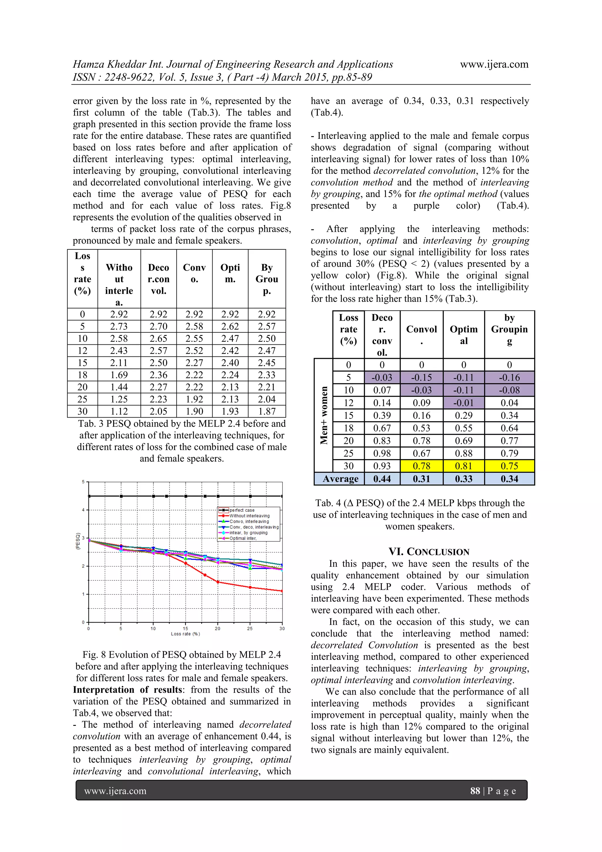
4- Performance of 2.4 MELP coder for different
types of interleaving
The interleaving techniques mentioned in the cf.
part.III have been implemented and led to the results
shown in Tab.3. The PESQ will be measured for
transmissions corresponding to losses of consecutive
packets. We have considered the loss of 1, 2 or 3
consecutive packets; these losses can be repeated
over the entire buffer of the signal, causing a global
MELP à 2.4 kbps
(PESQ)
Male speakers 2.99
Female speakers 2.89](https://image.slidesharecdn.com/p503048589-150331065214-conversion-gate01/75/Implementation-of-Interleaving-Methods-on-MELP-2-4-Coder-to-Reduce-Packet-Loss-in-the-Voice-over-IP-VoIP-Transmission-3-2048.jpg)
![Hamza Kheddar Int. Journal of Engineering Research and Applications www.ijera.com
ISSN : 2248-9622, Vol. 5, Issue 3, ( Part -4) March 2015, pp.85-89
www.ijera.com 89 | P a g e
REFERENCES
[1] G.Baudoin, J. Cernocký, P. Gournay, et G.
Chollet, Codage de la parole à bas et très bas
débit. Département Signaux et
Télécommunications, ESIEE BP 99 93162.
[2] J. Edward, Daniel and Keith A, Federal
Standard 2.4 kbps MELP Over IP,Roc. 43 rd
IEEE Midwest Symp. on Circuits and
Systems, Lansing MI, 0-7803-6475-9,
pp.568-571, Aug 8-11,2000.
[3] J. Stachurski, A. McCree, V. Viswanathan,
high quality MELP coding at bit-rates
around 4 kb/s. 0-7803-5041-3/99, pp 485-
488, IEEE 1999.
[4] C. Perkins, O. Hodson, et V. Hardman, A
Survey of Packet Loss Recovery Techniques
for Streaming Audio. 0890-8044, pp.40-48,
IEEE Network .September/October 1998.
[5] Teck-Kuen Chua and David C. Pheanis,
QoS Evaluation of Sender-Based Loss-
Recovery Techniques for VoIP. 0890-8044,
pp.14-22, IEEE Network.
November/December 2006.
[6] B.P. Milner, A.B. James. Analysis and
compensation of packet loss in distributed
speech recognition using interleaving,
pp.1947- 1950, ISCA-SPEECH. September
1-4, 2003.
[7] B.P. Milner, A.B. James, A Comparison of
Efficient Interleaver Designs for Real Time
Distributed Speech Recognition, ASIDE,
November 10-11. 2005.
[8] Gal Richard, E. Ravelli, Student et L.
Daudet, Union of MDCT Bases for Audio
Coding, IEEE transactions on audio,
speech, and language processing, vol. 16,
pp.1361-1372. No. 8, November 2008.
[9] ITU-T, Recommendation P.862, Perceptual
evaluation of speech quality (PESQ), an
objective method for end-to-end speech
quality assessment of narrowband telephone
networks and speech codecs. 2001.
[10] M. Boudraa, B. Boudraa, B. Guérin. Twenty
lists of Ten Arabic Sentences for
Assessment. Acustica, vol. 86, pp. 870-882,
2000.](https://image.slidesharecdn.com/p503048589-150331065214-conversion-gate01/75/Implementation-of-Interleaving-Methods-on-MELP-2-4-Coder-to-Reduce-Packet-Loss-in-the-Voice-over-IP-VoIP-Transmission-5-2048.jpg)

The document discusses methods to reduce packet loss in Voice over IP (VoIP) transmission using interleaving techniques on a MELP coder operating at 2.4 kbps. Various interleaving approaches were implemented and compared using the Perceptual Evaluation of Speech Quality (PESQ) technique, highlighting that the decorrelated convolution interleaver yielded the best improvements in voice quality for higher packet loss rates. The study concludes that while interleaving can enhance perceptual quality significantly at loss rates above 12%, its effectiveness diminishes near lower loss rates where performance is comparable to that of signals without interleaving.