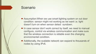
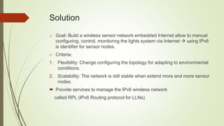
Outdoor Lighting System
Focus on fault management in outdoor lighting system
Scenario
 Assumption:When we use smart lighting system on out door
condition: sensor might not working as we want i.e. light
doesn't turn on when sensor detect sundown.
 In case sensor don’t work correct by itself, we need to manual
configure, control via wireless communication and make sure
that the wireless connection is reliable even the changing
environmental condition.
 Additionally, the scalable network can expand to thousands of
nodes by using IPv6.
Model
Standards
Solution
o Goal: Build a wireless sensor network embedded Internet allow to manual
configuring, control, monitoring the lights system via Internet  using IPv6
is identifier for sensor nodes.
o Criteria:
1. Flexibility: Change configuring the topology for adapting to environmental
conditions.
2. Scalability: The network is still stable when extend more and more sensor
nodes.
 Provide services to manage the IPv6 wireless network
called RPL (IPv6 Routing protocol for LLNs)
Stack
Hardware TelosB
 Microprocessor: 8 MHz MSP430 F1, 10kB RAM, 48kB Flash
 12bit A/D, 2 UART, 2 SPI …
 Radio: CC2420, 2.4GHz IEEE 802.15.4 compliance data rate 250kbps
 Humidity/ Temperature Sensor: SHT11
 Light Sensor: Ambient light, IR.
RPL
 IPv6 routing protocol for LLNs that specifies how to build logical routing
topology (graph) over physical network to meet specific criteria.
 The network administrator decide to have multiple graphs active with
different set of requirements.
 In this project, we set up the requirements:
 Flexible manage the network dynamically as well as manually
 Reliable connection between nodes
 Easily expand number of nodes as demand to widen the network.
Graph building process
 The gateway (root) starts
advertising the information about
the graph using DIO message.
 Upon the receive message, node
compute the rank – indicate the
relative position of node respect to
the root.
 Choose the best path toward to the
root by selecting the preferred
parents based on objective
function, metric (link quality, battery
node...)
 This process will repeat to
advertising DIO, compute rank and
do parents selection until leaf node
where the process terminated.
UPWARD Routing
 After this formation completed, each
node has routing entry toward its
parents also has reach-ability
toward the root  UPWARD routing
 We use this operation allow root
collect the information from all the
node of the network.
Link Reliability - ETX
 ETX metric is the expected number of transmission required to
successfully transmit and acknowledge a packet on the link
 This metric regards to the link reliability level to select parent that provides
delivery with the least number of transmission.
 The objective function decide the minimum-ETX path indicate the reliable
connection between nodes.
 formula: ETX= 1 / (Df * Dr) where Df is the measured probability that a
packet is received by the neighbor and Dr is the measured probability that
the acknowledgment packet is successfully received.
Repair
 Principles: A node is not
allowed to select as a parent a
neighboring node whose rank
is greater specific value
defined by node-rank+
max_depth.
 When link failure occur. A node
has no router parent will trigger
local repair to inform its child
nodes find another parent node
while itself find other node as a
parent (comply the rule).
DOWNWARD Routing
 When we have the traffic from outside the LLN network, at the root A send
the packet destined to node B. The root choose next-hop to forward IPv6
packet. This require the root A look up its routing table that contained the
path to the destination B. We use this traffic in order to manual control,
query the lighting sensor node.
 Routing table is built and populated by advertised DAO message.
 Operation: Each node joined the graph it will send DAO to its parent set.
As received the DAO message, node processes the prefix information and
add a entry into routing table. This process continues until the prefix
information reach the root.
Conclusion
 Solved the requirements set is setup when design the network.
 The latency is quite great.
 Development: Outdoor System is the key factor in Smart City with capable of
sense “things” in order to detect (or even predict) changes in the weather as
well as the congestion traffic in megacity.
1.6935
3.2797
5.1476
0
1
2
3
4
5
6
Group 1 Group 2 Group 3
AverageResponseTime(s)
Average Response Time

Outdoor lighting system

  • 1.
    Outdoor Lighting System Focuson fault management in outdoor lighting system
  • 2.
    Scenario  Assumption:When weuse smart lighting system on out door condition: sensor might not working as we want i.e. light doesn't turn on when sensor detect sundown.  In case sensor don’t work correct by itself, we need to manual configure, control via wireless communication and make sure that the wireless connection is reliable even the changing environmental condition.  Additionally, the scalable network can expand to thousands of nodes by using IPv6.
  • 3.
  • 4.
  • 5.
    Solution o Goal: Builda wireless sensor network embedded Internet allow to manual configuring, control, monitoring the lights system via Internet  using IPv6 is identifier for sensor nodes. o Criteria: 1. Flexibility: Change configuring the topology for adapting to environmental conditions. 2. Scalability: The network is still stable when extend more and more sensor nodes.  Provide services to manage the IPv6 wireless network called RPL (IPv6 Routing protocol for LLNs)
  • 6.
  • 7.
    Hardware TelosB  Microprocessor:8 MHz MSP430 F1, 10kB RAM, 48kB Flash  12bit A/D, 2 UART, 2 SPI …  Radio: CC2420, 2.4GHz IEEE 802.15.4 compliance data rate 250kbps  Humidity/ Temperature Sensor: SHT11  Light Sensor: Ambient light, IR.
  • 8.
    RPL  IPv6 routingprotocol for LLNs that specifies how to build logical routing topology (graph) over physical network to meet specific criteria.  The network administrator decide to have multiple graphs active with different set of requirements.  In this project, we set up the requirements:  Flexible manage the network dynamically as well as manually  Reliable connection between nodes  Easily expand number of nodes as demand to widen the network.
  • 9.
    Graph building process The gateway (root) starts advertising the information about the graph using DIO message.  Upon the receive message, node compute the rank – indicate the relative position of node respect to the root.  Choose the best path toward to the root by selecting the preferred parents based on objective function, metric (link quality, battery node...)  This process will repeat to advertising DIO, compute rank and do parents selection until leaf node where the process terminated.
  • 10.
    UPWARD Routing  Afterthis formation completed, each node has routing entry toward its parents also has reach-ability toward the root  UPWARD routing  We use this operation allow root collect the information from all the node of the network.
  • 11.
    Link Reliability -ETX  ETX metric is the expected number of transmission required to successfully transmit and acknowledge a packet on the link  This metric regards to the link reliability level to select parent that provides delivery with the least number of transmission.  The objective function decide the minimum-ETX path indicate the reliable connection between nodes.  formula: ETX= 1 / (Df * Dr) where Df is the measured probability that a packet is received by the neighbor and Dr is the measured probability that the acknowledgment packet is successfully received.
  • 12.
    Repair  Principles: Anode is not allowed to select as a parent a neighboring node whose rank is greater specific value defined by node-rank+ max_depth.  When link failure occur. A node has no router parent will trigger local repair to inform its child nodes find another parent node while itself find other node as a parent (comply the rule).
  • 13.
    DOWNWARD Routing  Whenwe have the traffic from outside the LLN network, at the root A send the packet destined to node B. The root choose next-hop to forward IPv6 packet. This require the root A look up its routing table that contained the path to the destination B. We use this traffic in order to manual control, query the lighting sensor node.  Routing table is built and populated by advertised DAO message.  Operation: Each node joined the graph it will send DAO to its parent set. As received the DAO message, node processes the prefix information and add a entry into routing table. This process continues until the prefix information reach the root.
  • 14.
    Conclusion  Solved therequirements set is setup when design the network.  The latency is quite great.  Development: Outdoor System is the key factor in Smart City with capable of sense “things” in order to detect (or even predict) changes in the weather as well as the congestion traffic in megacity. 1.6935 3.2797 5.1476 0 1 2 3 4 5 6 Group 1 Group 2 Group 3 AverageResponseTime(s) Average Response Time