This document provides specifications for an insulated gate bipolar transistor (IGBT) with an integrated ultrafast soft recovery diode.
1) It lists maximum ratings and electrical characteristics such as a collector-emitter breakdown voltage of 600V, on-state voltage of 2.27V at 15V gate voltage and 9A collector current, and short circuit withstand time of 10us.
2) Switching characteristics are provided including turn-on delay, rise time, turn-off delay, and fall time over temperature ranges.
3) Graphs illustrate characteristics such as output, transfer and switching loss curves versus variables like gate resistance, current, and temperature.
4) Test circuits and waveforms define switching
Original N-Channel Mosfet IRF2907ZPBF 2907 75V 170A TO-220 New IRAUTHELECTRONIC
Original N-Channel Mosfet IRF2907ZPBF 2907 75V 170A TO-220 New IR
https://authelectronic.com/original-n-channel-mosfet-irf2907zpbf-2907-75v-170a-to-220-new-ir
Original N-Channel Mosfet IRF2907ZPBF 2907 75V 170A TO-220 New IRAUTHELECTRONIC
Original N-Channel Mosfet IRF2907ZPBF 2907 75V 170A TO-220 New IR
https://authelectronic.com/original-n-channel-mosfet-irf2907zpbf-2907-75v-170a-to-220-new-ir
Original N-Channel Mosfet IRFB3077PBF IRFB3077 3077 75V 120A TO-220 New IRAUTHELECTRONIC
Original N-Channel Mosfet IRFB3077PBF IRFB3077 3077 75V 120A TO-220 New IR
https://authelectronic.com/original-n-channel-mosfet-irfb3077pbf-irfb3077-3077-75v-120a-to-220-new-ir
Original Mosfet IRFB18N50KPBF IRFB18N50K FB18N50K 18N50K 500V 17A TO-220 New ...AUTHELECTRONIC
Original Mosfet IRFB18N50KPBF IRFB18N50K FB18N50K 18N50K 500V 17A TO-220 New International Rectifier
https://authelectronic.com/original-mosfet-irfb18n50kpbf-irfb18n50k-fb18n50k-18n50k-500v-17a-to-220-new-international-rectifier
Original N-channel 650 V 0.230 Ohm 12 A MDmesh V Power MOSFET in DPAK DPAK ST...AUTHELECTRONIC
Original N-channel 650 V 0.230 Ohm 12 A MDmesh V Power MOSFET in DPAK DPAK STF16N65M5 16N65M5 16N65 710V 12A TO-220FP New STMicroelectronics
https://authelectronic.com/original-n-channel-650-v-0-230-ohm-12-a-mdmesh-v-power-mosfet-in-dpak-dpak-stf16n65m5-16n65m5-16n65-710v-12a-to-220fp-new-stmicroelectronics
Similar to Original IGBT IRG4BC20KD-S G4BC20KD 600V 9A TO-263 New (14)
Immunizing Image Classifiers Against Localized Adversary Attacksgerogepatton
This paper addresses the vulnerability of deep learning models, particularly convolutional neural networks
(CNN)s, to adversarial attacks and presents a proactive training technique designed to counter them. We
introduce a novel volumization algorithm, which transforms 2D images into 3D volumetric representations.
When combined with 3D convolution and deep curriculum learning optimization (CLO), itsignificantly improves
the immunity of models against localized universal attacks by up to 40%. We evaluate our proposed approach
using contemporary CNN architectures and the modified Canadian Institute for Advanced Research (CIFAR-10
and CIFAR-100) and ImageNet Large Scale Visual Recognition Challenge (ILSVRC12) datasets, showcasing
accuracy improvements over previous techniques. The results indicate that the combination of the volumetric
input and curriculum learning holds significant promise for mitigating adversarial attacks without necessitating
adversary training.
Saudi Arabia stands as a titan in the global energy landscape, renowned for its abundant oil and gas resources. It's the largest exporter of petroleum and holds some of the world's most significant reserves. Let's delve into the top 10 oil and gas projects shaping Saudi Arabia's energy future in 2024.
NO1 Uk best vashikaran specialist in delhi vashikaran baba near me online vas...Amil Baba Dawood bangali
Contact with Dawood Bhai Just call on +92322-6382012 and we'll help you. We'll solve all your problems within 12 to 24 hours and with 101% guarantee and with astrology systematic. If you want to take any personal or professional advice then also you can call us on +92322-6382012 , ONLINE LOVE PROBLEM & Other all types of Daily Life Problem's.Then CALL or WHATSAPP us on +92322-6382012 and Get all these problems solutions here by Amil Baba DAWOOD BANGALI
#vashikaranspecialist #astrologer #palmistry #amliyaat #taweez #manpasandshadi #horoscope #spiritual #lovelife #lovespell #marriagespell#aamilbabainpakistan #amilbabainkarachi #powerfullblackmagicspell #kalajadumantarspecialist #realamilbaba #AmilbabainPakistan #astrologerincanada #astrologerindubai #lovespellsmaster #kalajaduspecialist #lovespellsthatwork #aamilbabainlahore#blackmagicformarriage #aamilbaba #kalajadu #kalailam #taweez #wazifaexpert #jadumantar #vashikaranspecialist #astrologer #palmistry #amliyaat #taweez #manpasandshadi #horoscope #spiritual #lovelife #lovespell #marriagespell#aamilbabainpakistan #amilbabainkarachi #powerfullblackmagicspell #kalajadumantarspecialist #realamilbaba #AmilbabainPakistan #astrologerincanada #astrologerindubai #lovespellsmaster #kalajaduspecialist #lovespellsthatwork #aamilbabainlahore #blackmagicforlove #blackmagicformarriage #aamilbaba #kalajadu #kalailam #taweez #wazifaexpert #jadumantar #vashikaranspecialist #astrologer #palmistry #amliyaat #taweez #manpasandshadi #horoscope #spiritual #lovelife #lovespell #marriagespell#aamilbabainpakistan #amilbabainkarachi #powerfullblackmagicspell #kalajadumantarspecialist #realamilbaba #AmilbabainPakistan #astrologerincanada #astrologerindubai #lovespellsmaster #kalajaduspecialist #lovespellsthatwork #aamilbabainlahore #Amilbabainuk #amilbabainspain #amilbabaindubai #Amilbabainnorway #amilbabainkrachi #amilbabainlahore #amilbabaingujranwalan #amilbabainislamabad
Overview of the fundamental roles in Hydropower generation and the components involved in wider Electrical Engineering.
This paper presents the design and construction of hydroelectric dams from the hydrologist’s survey of the valley before construction, all aspects and involved disciplines, fluid dynamics, structural engineering, generation and mains frequency regulation to the very transmission of power through the network in the United Kingdom.
Author: Robbie Edward Sayers
Collaborators and co editors: Charlie Sims and Connor Healey.
(C) 2024 Robbie E. Sayers
Cosmetic shop management system project report.pdfKamal Acharya
Buying new cosmetic products is difficult. It can even be scary for those who have sensitive skin and are prone to skin trouble. The information needed to alleviate this problem is on the back of each product, but it's thought to interpret those ingredient lists unless you have a background in chemistry.
Instead of buying and hoping for the best, we can use data science to help us predict which products may be good fits for us. It includes various function programs to do the above mentioned tasks.
Data file handling has been effectively used in the program.
The automated cosmetic shop management system should deal with the automation of general workflow and administration process of the shop. The main processes of the system focus on customer's request where the system is able to search the most appropriate products and deliver it to the customers. It should help the employees to quickly identify the list of cosmetic product that have reached the minimum quantity and also keep a track of expired date for each cosmetic product. It should help the employees to find the rack number in which the product is placed.It is also Faster and more efficient way.
Hierarchical Digital Twin of a Naval Power SystemKerry Sado
A hierarchical digital twin of a Naval DC power system has been developed and experimentally verified. Similar to other state-of-the-art digital twins, this technology creates a digital replica of the physical system executed in real-time or faster, which can modify hardware controls. However, its advantage stems from distributing computational efforts by utilizing a hierarchical structure composed of lower-level digital twin blocks and a higher-level system digital twin. Each digital twin block is associated with a physical subsystem of the hardware and communicates with a singular system digital twin, which creates a system-level response. By extracting information from each level of the hierarchy, power system controls of the hardware were reconfigured autonomously. This hierarchical digital twin development offers several advantages over other digital twins, particularly in the field of naval power systems. The hierarchical structure allows for greater computational efficiency and scalability while the ability to autonomously reconfigure hardware controls offers increased flexibility and responsiveness. The hierarchical decomposition and models utilized were well aligned with the physical twin, as indicated by the maximum deviations between the developed digital twin hierarchy and the hardware.
About
Indigenized remote control interface card suitable for MAFI system CCR equipment. Compatible for IDM8000 CCR. Backplane mounted serial and TCP/Ethernet communication module for CCR remote access. IDM 8000 CCR remote control on serial and TCP protocol.
• Remote control: Parallel or serial interface.
• Compatible with MAFI CCR system.
• Compatible with IDM8000 CCR.
• Compatible with Backplane mount serial communication.
• Compatible with commercial and Defence aviation CCR system.
• Remote control system for accessing CCR and allied system over serial or TCP.
• Indigenized local Support/presence in India.
• Easy in configuration using DIP switches.
Technical Specifications
Indigenized remote control interface card suitable for MAFI system CCR equipment. Compatible for IDM8000 CCR. Backplane mounted serial and TCP/Ethernet communication module for CCR remote access. IDM 8000 CCR remote control on serial and TCP protocol.
Key Features
Indigenized remote control interface card suitable for MAFI system CCR equipment. Compatible for IDM8000 CCR. Backplane mounted serial and TCP/Ethernet communication module for CCR remote access. IDM 8000 CCR remote control on serial and TCP protocol.
• Remote control: Parallel or serial interface
• Compatible with MAFI CCR system
• Copatiable with IDM8000 CCR
• Compatible with Backplane mount serial communication.
• Compatible with commercial and Defence aviation CCR system.
• Remote control system for accessing CCR and allied system over serial or TCP.
• Indigenized local Support/presence in India.
Application
• Remote control: Parallel or serial interface.
• Compatible with MAFI CCR system.
• Compatible with IDM8000 CCR.
• Compatible with Backplane mount serial communication.
• Compatible with commercial and Defence aviation CCR system.
• Remote control system for accessing CCR and allied system over serial or TCP.
• Indigenized local Support/presence in India.
• Easy in configuration using DIP switches.
Student information management system project report ii.pdfKamal Acharya
Our project explains about the student management. This project mainly explains the various actions related to student details. This project shows some ease in adding, editing and deleting the student details. It also provides a less time consuming process for viewing, adding, editing and deleting the marks of the students.
Explore the innovative world of trenchless pipe repair with our comprehensive guide, "The Benefits and Techniques of Trenchless Pipe Repair." This document delves into the modern methods of repairing underground pipes without the need for extensive excavation, highlighting the numerous advantages and the latest techniques used in the industry.
Learn about the cost savings, reduced environmental impact, and minimal disruption associated with trenchless technology. Discover detailed explanations of popular techniques such as pipe bursting, cured-in-place pipe (CIPP) lining, and directional drilling. Understand how these methods can be applied to various types of infrastructure, from residential plumbing to large-scale municipal systems.
Ideal for homeowners, contractors, engineers, and anyone interested in modern plumbing solutions, this guide provides valuable insights into why trenchless pipe repair is becoming the preferred choice for pipe rehabilitation. Stay informed about the latest advancements and best practices in the field.
Original IGBT IRG4BC20KD-S G4BC20KD 600V 9A TO-263 New
1. Parameter Max. Units
VCES Collector-to-Emitter Voltage 600 V
IC @ TC = 25°C Continuous Collector Current 16
IC @ TC = 100°C Continuous Collector Current 9.0
ICM Pulsed Collector Current Q 32 A
ILM Clamped Inductive Load Current R 32
IF @ TC = 100°C Diode Continuous Forward Current 7.0
IFM Diode Maximum Forward Current 32
tsc Short Circuit Withstand Time 10 µs
VGE Gate-to-Emitter Voltage ± 20 V
PD @ TC = 25°C Maximum Power Dissipation 60
PD @ TC = 100°C Maximum Power Dissipation 24
TJ Operating Junction and -55 to +150
TSTG Storage Temperature Range °C
Soldering Temperature, for 10 sec. 300 (0.063 in. (1.6mm) from case)
Mounting Torque, 6-32 or M3 Screw. 10 lbf•in (1.1 N•m)
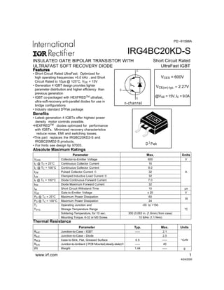
IRG4BC20KD-S
INSULATED GATE BIPOLAR TRANSISTOR WITH
ULTRAFAST SOFT RECOVERY DIODE
FeaturesFeaturesFeaturesFeaturesFeatures
E
G
n-channel
C
VCES = 600V
VCE(on) typ. = 2.27V
@VGE = 15V, IC = 9.0A
Short Circuit Rated
UltraFast IGBT
4/24/2000
• Short Circuit Rated UltraFast: Optimized for
high operating frequencies >5.0 kHz , and Short
Circuit Rated to 10µs @ 125°C, VGE = 15V
• Generation 4 IGBT design provides tighter
parameter distribution and higher efficiency than
previous generation
• IGBT co-packaged with HEXFREDTM ultrafast,
ultra-soft-recovery anti-parallel diodes for use in
bridge configurations
• Industry standard D2Pak package
Benefits
• Latest generation 4 IGBTs offer highest power
density motor controls possible.
•HEXFREDTM diodes optimized for performance
with IGBTs. Minimized recovery characteristics
reduce noise, EMI and switching losses.
•This part replaces the IRGBC20KD2-S and
IRGBC20MD2-S products.
• For hints see design tip 97003.
PD -91598A
Absolute Maximum Ratings
W
2
D Pak
Parameter Typ. Max. Units
RθJC Junction-to-Case - IGBT ––– 2.1
RθJC Junction-to-Case - Diode 2.5
RθCS Case-to-Sink, Flat, Greased Surface 0.5 ––– °C/W
RθJA Junction-to-Ambient ( PCB Mounted,steady-state)U ––– 40
Wt Weight 1.44 ––– g
Thermal Resistance
www.irf.com 1
2. IRG4BC20KD-S
2 www.irf.com
Parameter Min. Typ. Max. Units Conditions
Qg Total Gate Charge (turn-on) — 34 51 IC = 9.0A
Qge Gate - Emitter Charge (turn-on) — 4.9 7.4 nC VCC = 400V See Fig.8
Qgc Gate - Collector Charge (turn-on) — 14 21 VGE = 15V
td(on) Turn-On Delay Time — 54 —
tr Rise Time — 34 — TJ = 25°C
td(off) Turn-Off Delay Time — 180 270 IC = 9.0A, VCC = 480V
tf Fall Time — 72 110 VGE = 15V, RG = 50Ω
Eon Turn-On Switching Loss — 0.34 — Energy losses include "tail"
Eoff Turn-Off Switching Loss — 0.30 — mJ and diode reverse recovery
Ets Total Switching Loss — 0.64 0.96 See Fig. 9,10,14
tsc Short Circuit Withstand Time 10 — — µs VCC = 360V, TJ = 125°C
VGE = 15V, RG = 50Ω , VCPK < 500V
td(on) Turn-On Delay Time — 51 — TJ = 150°C, See Fig. 11,14
tr Rise Time — 37 — IC = 9.0A, VCC = 480V
td(off) Turn-Off Delay Time — 220 — VGE = 15V, RG = 50Ω
tf Fall Time — 160 — Energy losses include "tail"
Ets Total Switching Loss — 0.85 — mJ and diode reverse recovery
LE Internal Emitter Inductance — 7.5 — nH Measured 5mm from package
Cies Input Capacitance — 450 — VGE = 0V
Coes Output Capacitance — 61 — pF VCC = 30V See Fig. 7
Cres Reverse Transfer Capacitance — 14 — ƒ = 1.0MHz
trr Diode Reverse Recovery Time — 37 55 ns TJ = 25°C See Fig.
— 55 90 TJ = 125°C 14 IF = 8.0A
Irr Diode Peak Reverse Recovery Current — 3.5 5.0 A TJ = 25°C See Fig.
— 4.5 8.0 TJ = 125°C 15 VR = 200V
Qrr Diode Reverse Recovery Charge — 65 138 nC TJ = 25°C See Fig.
— 124 360 TJ = 125°C 16 di/dt = 200Aµs
di(rec)M/dt Diode Peak Rate of Fall of Recovery — 240 — A/µs TJ = 25°C See Fig.
During tb — 210 — TJ = 125°C 17
Parameter Min. Typ. Max. Units Conditions
V(BR)CES Collector-to-Emitter Breakdown VoltageS 600 — — V VGE = 0V, IC = 250µA
∆V(BR)CES/∆TJ Temperature Coeff. of Breakdown Voltage — 0.49 — V/°C VGE = 0V, IC = 1.0mA
VCE(on) Collector-to-Emitter Saturation Voltage — 2.27 2.8 IC = 9.0A VGE = 15V
— 3.01 — V IC = 16A See Fig. 2, 5
— 2.43 — IC = 9.0A, TJ = 150°C
VGE(th) Gate Threshold Voltage 3.0 — 6.0 VCE = VGE, IC = 250µA
∆VGE(th)/∆TJ Temperature Coeff. of Threshold Voltage — -10 — mV/°C VCE = VGE, IC = 250µA
gfe Forward Transconductance T 2.9 4.3 — S VCE = 100V, IC = 9.0A
ICES Zero Gate Voltage Collector Current — — 250 µA VGE = 0V, VCE = 600V
— — 1000 VGE = 0V, VCE = 600V, TJ = 150°C
VFM Diode Forward Voltage Drop — 1.4 1.7 V IC = 8.0A See Fig. 13
— 1.3 1.6 IC = 8.0A, TJ = 150°C
IGES Gate-to-Emitter Leakage Current — — ±100 nA VGE = ±20V
Switching Characteristics @ TJ = 25°C (unless otherwise specified)
Electrical Characteristics @ TJ = 25°C (unless otherwise specified)
ns
ns
3. IRG4BC20KD-S
www.irf.com 3
0.1 1 10 100
0.0
0.5
1.0
1.5
2.0
2.5
f, Frequency (KHz)
LOADCURRENT(A)
Fig. 1 - Typical Load Current vs. Frequency
(Load Current = IRMS of fundamental)
For both:
Duty cycle: 50%
T = 125°C
T = 90°C
Gate drive as specified
sink
J
Power Dissipation = W
60% of rated
voltage
I
Ideal diodes
Square wave:
1.8
Fig. 2 - Typical Output Characteristics Fig. 3 - Typical Transfer Characteristics
1
10
100
1 10
V , Collector-to-Emitter Voltage (V)
I,Collector-to-EmitterCurrent(A)
CE
C
V = 15V
20µs PULSE WIDTH
GE
T = 25 CJ
o
T = 150 CJ
o
1
10
100
5 10 15 20
V , Gate-to-Emitter Voltage (V)
I,Collector-to-EmitterCurrent(A)
GE
C
V = 50V
5µs PULSE WIDTH
CC
T = 25 CJ
o
T = 150 CJ
o
55°C
4. IRG4BC20KD-S
4 www.irf.com
Fig. 6 - Maximum Effective Transient Thermal Impedance, Junction-to-Case
Fig. 5 - Typical Collector-to-Emitter Voltage
vs. Junction Temperature
Fig. 4 - Maximum Collector Current vs. Case
Temperature
-60 -40 -20 0 20 40 60 80 100 120 140 160
1.0
2.0
3.0
4.0
5.0
T , Junction Temperature ( C)
V,Collector-to-EmitterVoltage(V)
J °
CE
V = 15V
80 us PULSE WIDTH
GE
I = A4.5C
I = A9C
I = A18C
25 50 75 100 125 150
0
5
10
15
20
T , Case Temperature ( C)
MaximumDCCollectorCurrent(A)
C °
0.01
0.1
1
10
0.00001 0.0001 0.001 0.01 0.1 1
Notes:
1. Duty factor D = t / t
2. Peak T = P x Z + T
1 2
J DM thJC C
P
t
t
DM
1
2
t , Rectangular Pulse Duration (sec)
ThermalResponse(Z)
1
thJC
0.01
0.02
0.05
0.10
0.20
D = 0.50
SINGLE PULSE
(THERMAL RESPONSE)
9.0A
5. IRG4BC20KD-S
www.irf.com 5
0 10 20 30 40 50
0.5
0.6
0.7
0.8
R , Gate Resistance (Ohm)
TotalSwitchingLosses(mJ)
G
V = 480V
V = 15V
T = 25 C
I = 9.0A
CC
GE
J
C
°
Fig. 7 - Typical Capacitance vs.
Collector-to-Emitter Voltage
Fig. 8 - Typical Gate Charge vs.
Gate-to-Emitter Voltage
Fig. 9 - Typical Switching Losses vs. Gate
Resistance
Fig. 10 - Typical Switching Losses vs.
Junction Temperature
0 10 20 30 40
0
4
8
12
16
20
Q , Total Gate Charge (nC)
V,Gate-to-EmitterVoltage(V)
G
GE
V = 400V
I = 9.0A
CC
C
1 10 100
0
200
400
600
800
V , Collector-to-Emitter Voltage (V)
C,Capacitance(pF)
CE
V
C
C
C
=
=
=
=
0V,
C
C
C
f = 1MHz
+ C
+ C
C SHORTED
GE
ies ge gc , ce
res gc
oes ce gc
Cies
Coes
Cres
RG , Gate Resistance ( Ω )
-60 -40 -20 0 20 40 60 80 100 120 140 160
0.1
1
10
T , Junction Temperature ( C )
TotalSwitchingLosses(mJ)
J °
R = Ohm
V = 15V
V = 480V
G
GE
CC
I = A18C
I = A9C
I = A4.5C
50Ω
9.0A
6. IRG4BC20KD-S
6 www.irf.com
Fig. 11 - Typical Switching Losses vs.
Collector-to-Emitter Current
Fig. 12 - Turn-Off SOA
1
10
100
1 10 100 1000
V = 20V
T = 125 C
GE
J
o
V , Collector-to-Emitter Voltage (V)I,Collector-to-EmitterCurrent(A) CEC
SAFE OPERATING AREA
Fig. 13 - Maximum Forward Voltage Drop vs. Instantaneous Forward Current
0.1
1
10
100
0.4 0.8 1.2 1.6 2.0 2.4 2.8 3.2
FM
FInstantaneousForwardCurrent-I(A)
Forward Voltage Drop - V (V)
T = 150°C
T = 125°C
T = 25°C
J
J
J
0 4 8 12 16 20
0.0
1.0
2.0
3.0
I , Collector-to-emitter Current (A)
TotalSwitchingLosses(mJ)
C
R = Ohm
T = 150 C
V = 480V
V = 15V
G
J
CC
GE
°
50Ω
7. IRG4BC20KD-S
www.irf.com 7
Fig. 14 - Typical Reverse Recovery vs. dif/dt Fig. 15 - Typical Recovery Current vs. dif/dt
Fig. 16 - Typical Stored Charge vs. dif/dt Fig. 17 - Typical di(rec)M/dt vs. dif/dt
0
100
200
300
400
500
100 1000
fdi /dt - (A/µs)
RRQ-(nC)
I = 16A
I = 8.0A
I = 4.0AF
F
F
V = 200V
T = 125°C
T = 25°C
R
J
J
100
1000
10000
100 1000
fdi /dt - (A/µs)
di(rec)M/dt-(A/µs)
I = 16A
I = 8.0A
I = 4.0A
F
F
F
V = 200V
T = 125°C
T = 25°C
R
J
J
0
20
40
60
80
100
100 1000
fdi /dt - (A/µs)
t-(ns)rr
I = 16A
I = 8.0A
I = 4.0A
F
F
F
V = 200V
T = 125°C
T = 25°C
R
J
J
1
10
100
100 1000
fdi /dt - (A/µs)
I-(A)IRRM
I = 16A
I = 8.0A
I = 4.0AF
F
F
V = 200V
T = 125°C
T = 25°C
R
J
J
8. IRG4BC20KD-S
8 www.irf.com
Same type
device as
D.U.T.
D.U.T.
430µF
80%
of Vce
Fig. 18a - Test Circuit for Measurement of
ILM, Eon, Eoff(diode), trr, Qrr, Irr, td(on), tr, td(off), tf
t1
Ic
Vce
t1 t2
90% Ic
10% Vce
td(off) tf
Ic
5% Ic
t1+5µS
Vce ic dt
90% Vge
+Vge
∫Eoff =
Fig. 18b - Test Waveforms for Circuit of Fig. 18a, Defining
Eoff, td(off), tf
∫Vce ie dt
t2
t1
5% Vce
Ic
IpkVcc
10% Ic
Vce
t1 t2
D UT VO LTAGE
AN D CU RRE NT
GATE VOLTA GE D .U .T.
+Vg
10% +Vg
90% Ic
trtd(on)
DIO DE REVE RSE
REC OVERY ENER GY
tx
E on =
∫Erec =
t4
t3
Vd id dt
t4t3
DIODE RE COV ERY
W AVEFO RMS
Ic
V pk
10% Vcc
Irr
10% Irr
Vcc
trr
∫Q rr =
trr
tx
id dt
Fig. 18c - Test Waveforms for Circuit of Fig. 18a,
Defining Eon, td(on), tr
Fig. 18d - Test Waveforms for Circuit of Fig. 18a,
Defining Erec, trr, Qrr, Irr
Vd Ic dt
Vce Ic dt
Ic dt
Vce Ic dt
9. IRG4BC20KD-S
www.irf.com 9
Vg GATE SIGNAL
DEVICE UNDER TEST
CURRENT D.U.T.
VOLTAGE IN D.U.T.
CURRENT IN D1
t0 t1 t2
D.U.T.
V *c
5 0 V
L
1000V
6000µF
100V
Figure 19. Clamped Inductive Load Test Circuit Figure 20. Pulsed Collector Current
Test Circuit
RL=
480V
4 X IC @25°C
0 - 480V
Figure 18e. Macro Waveforms for Figure 18a's Test Circuit
Tape Reel Information
D2Pak
3
4
4
TR R
FEED D IRECTION
1.85 (.0 73)
1.65 (.0 65)
1.60 (.063)
1.50 (.059)
4.10 (.161)
3.90 (.153)
TRL
FE ED DIRE CTION
10.90 (.429)
10.70 (.421)
16.10 (.634)
15.90 (.626)
1.75 (.069)
1.25 (.049)
11.60 (.457)
11.40 (.449)
15.42 (.609)
15.22 (.601)
4.72 (.136)
4.52 (.178)
24.30 (.957)
23.90 (.941)
0.368 (.0145)
0.342 (.0135)
1.60 (.063)
1.50 (.059)
13.50 (.532)
12.80 (.504)
330.00
(14.173)
MAX.
27.40 (1.079)
23.90 (.941)
60.00 (2.362)
MIN.
30.40 (1.197)
MAX.
26.40 (1.039)
24.40 (.961)
NOTES :
1. CO MFORMS TO EIA-418.
2. CO NTRO LLING DIMENSIO N: MILLIMETER.
3. DIMENSIO N MEASUR ED @ HU B.
4. INCLUDES FLANG E DISTORTIO N @ OUTER EDGE.
10. IRG4BC20KD-S
10 www.irf.com
1 0.16 (.40 0)
REF .
6.47 (.25 5)
6.18 (.24 3)
2.61 (.10 3)
2.32 (.09 1)
8.8 9 (.35 0)
R E F.
- B -
1.32 (.0 52)
1.22 (.0 48)
2.79 (.1 10)
2.29 (.0 90)
1 .39 (.055 )
1 .14 (.045 )
5 .28 (.2 08 )
4 .78 (.1 88 )
4.69 (.18 5)
4.20 (.16 5)
10.5 4 (.4 15)
10.2 9 (.4 05)
- A -
2
1 3
1 5.49 (.61 0)
1 4.73 (.58 0)
3 X
0.9 3 (.0 37)
0.6 9 (.0 27)
5.08 (.20 0)
3 X
1.40 (.0 55)
1.14 (.0 45)
1.78 (.07 0)
1.27 (.05 0)
1.40 (.055 )
M A X.
N O T ES :
1 D IM EN S IO N S AF T E R S OL D ER D IP.
2 D IM EN S IO N ING TO L ERA N C IN G P ER AN SI Y 14 .5M , 198 2.
3 C O NT RO L LIN G D IM E NSIO N : IN C H.
4 H EAT SINK LE AD D IM EN S IO N S DO N O T INC L UD E BUR R S.
0.55 (.0 22)
0.46 (.0 18)
0.25 (.0 10) M B A M M IN IM U M R E CO M M EN DE D F O OT PR IN T
11 .43 (.4 50 )
8.89 (.3 50 )
17.7 8 (.7 00 )
3 .8 1 (.150 )
2 .08 (.082 )
2X
LEA D A SS IG NM EN T S
1 - G A TE
2 - D R AIN
3 - S O U RC E
2.5 4 (.1 00)
2X
D2Pak Package Outline
Notes:
QRepetitiverating:VGE=20V;pulsewidthlimitedbymaximumjunctiontemperature(figure20)
RVCC=80%(VCES),VGE=20V,L=10µH,RG=50Ω(figure19)
SPulsewidth≤80µs;dutyfactor≤0.1%.
TPulsewidth5.0µs,singleshot.
U When mounted on 1 square PCB (FR-4 or G-10 Material ).
For recommended footprint and soldering techniques refer to application note #AN-994.
IR WORLD HEADQUARTERS: 233 Kansas St., El Segundo, California 90245, USA Tel: (310) 252-7105
IR EUROPEAN REGIONAL CENTRE: 439/445 Godstone Rd, Whyteleafe, Surrey CR3 OBL, UK Tel: ++ 44 (0)20 8645 8000
IR CANADA: 15 Lincoln Court, Brampton, Ontario L6T3Z2, Tel: (905) 453 2200
IR GERMANY: Saalburgstrasse 157, 61350 Bad Homburg Tel: ++ 49 (0) 6172 96590
IR ITALY: Via Liguria 49, 10071 Borgaro, Torino Tel: ++ 39 011 451 0111
IR JAPAN: KH Bldg., 2F, 30-4 Nishi-Ikebukuro 3-Chome, Toshima-Ku, Tokyo 171 Tel: 81 (0)3 3983 0086
IR SOUTHEAST ASIA: 1 Kim Seng Promenade, Great World City West Tower, 13-11, Singapore 237994 Tel: ++ 65 (0)838 4630
IR TAIWAN:16 Fl. Suite D. 207, Sec. 2, Tun Haw South Road, Taipei, 10673 Tel: 886-(0)2 2377 9936
Data and specifications subject to change without notice. 10/00
11. Note: For the most current drawings please refer to the IR website at:
http://www.irf.com/package/