SlideShare a Scribd company logo
Orifice Flows Can Lie
Orifice flow measurement not only needs compensation for
temperature and pressure but also correction for inaccurate
calculations. This article will simplify those calculation into a
ready to use formula.
Orifice flow meters are one of the most commonly used flow
measurement devices used in the industry. They are cheap,
easy to maintain, easily replaceable and generic. Typically the
accuracy of these meters is within +/- 2% of measured value
which is mostly acceptable to clients. But this accuracy is
contingent on the calculation behind flow measurement using
orifice, specifically flow correction for temperature and
pressure changes. A flow meter reading can be completely off
if wrong compensations are used.
Let’s understand how flow is measured by an orifice. Orifice is
simply a flow restriction with known behavior i.e. the
performance or orifice w.r.t. flow can be defined quantitatively
by using empirically established equations. Certain flow causes
certain delta P under given conditions. In practical
applications, the delta P produced across the orifice due to
flow through it is used to estimate the flow. These calculations
require temperature, pressure and density amongst other
parameters and constants.
The transmitters in plant uses design values of T, P and density
(rho) to do these calculations whereas, in actual, the flowing
conditions are often different. It is important to know how to
correct the flow displayed on control board/DCS. This is what
the article will talk about in a practical perspective.
An abridged version of orifice equation goes like,
(1)
For gasses, we can write
(2)
(3)
Where,
V = Actual volumetric flow (Am3/hr)
Rho = flowing density (kg/m3)
Remember, the delta P measured by transmitter remains fixed
for a given flow and conditions, it’s just the conversion of delta
P to flow using equations that can be done differently to arrive
at correct or incorrect values. The flow transmitter does these
calculations by using the values fed into it, which are the
design values. The required correction is to change the T, P,
rho used in these calculations from design to flowing values.
Since delta P is same, the uncorrected and corrected flows are
related. Using previous equation, we get
(4)
Rearranging, we get
(5)
Where, subscript “old” refers to the design value being used in
calculations and “f” means the properties at actual flowing
conditions.
Also, from ideal gas equation, we know
(6)
Where again, subscript “d” stands for design conditions
(considered in orifice and flow meter datasheet).
Using the two previous equations, the observed reading can
be corrected to get actual reading. This is commonly done by
a flow compensation feature in modern digital systems in DCS.
The values of T and P needs to be imported to the calculation
block configured in DCS and the flow value shown on control
board/panel is then the compensated value.
F
Flow
Compensation
PT TTFT
Flow Orifice
Delta P based flow
transmitter
Pressure and
Temperature
transmitter
Fig. 1: T and P compensation in Flow Transmitters
Tushar Goel
Chemical Engineer
IIT (BHU), Varanasi
Above shown configuration is one of the most commonly used
flow compensation system at the battery limit flows of plant
for accurate measurement of import and export streams.
Actual volumetric flow vs Normal volumetric flow
But this is just the beginning of corrections and
compensations. Many clients prefer their flow measurements
represented on a standard or normal conditions for easy
comparison. This makes it easy to communicate the flow
values by eliminating the need to tell P and T every time the
flow value is reported. Typically the normal conditions are 0
deg C and 1 atm i.e. the flow reported in Nm3/hr is always at
273.15 K and 1.033 kg/cm2a.
where, Flowing Pressure (Pf) and Flowing Temperature (Tf) are
expressed in units of kg/cm2 (g) and °C.
As one can see, once again the use of T, P arises to covert the
flows from actual to normal conditions. If flowing conditions
(Tf, Pf) are not provided to the calculation block, design
conditions will be used by default, which is again bound to give
wrong flow values.
Correcting the uncorrected flows represented at normal
conditions (Nm3/hr)
One of the tedious tasks for a process engineer is to correct
the uncompensated and uncorrected DCS reading into correct
flow measurements. The calculation to convert Am3/hr to
Nm3/hr was done by DCS by using design T and P while actually
the flowing T and P are different. This needs to be corrected.
Below flowchart explain the process of doing the calculations.
Let us consider an example:
Td = 10 deg C
Pd = 2.2 kg/cm2g
Rhod = 3.8597 kg/m3
MWd = 28.03
Tf = 20 deg C (measured by instrument)
Pf = 2.7 kg/cm2g (measured by instrument)
MWf = 22.8 (as provided by laboratory sample analysis)
Flow as shown on DCS screen = 4000 Nm3/hr which is
uncorrected and uncompensated.
Converting the Nm3/hr to Am3/hr (uncorrected)
= 4000 ∗ (
1.033
1.033+2.2
) ∗ (
10+273.15
273.15
)
= 1324.86 Am3/hr (uncorrected)
Now, we know
(7)
𝑟ℎ𝑜_𝑜𝑙𝑑
𝑟ℎ𝑜_𝑛𝑒𝑤
=
(2.2 + 1.033)
2.7 + 1.033
∗
20 + 273.15
10 + 273.15
∗ (
28.03
22.8
)
So we get, rhoold/rhonew = 1.104717
Now using the correction formula from eq. (5)
And finally converting the Am3/hr to Nm3/hr based on actual
flowing conditions, we get
The correct flow is 4688.83 vs 4000 Nm3/hr as shown on DCS
screen which equals to 17% error in measurement. The above
calculations are summarized in the following single formula for
correction of gas flows reported in Nm3/hr:
Convert the measured Nm3/hr
to Am3/hr based on Design
conditions
The DCS system has
incorporated a calculation which
converts the Am3/hr to Nm3/hr
based on DESIGN
CONDITIONS. But the conditions
have changed to FLOWING
CONDITIONS, so you would like
to undo those calculations.
Correct this Am3/hr by using
the orifice correlation.
Convert the Corrected
Am3/hr back to Nm3/hr based
on actual flowing conditions
The Am3/hr that we got in
previous step was calculated
based on ΔP observed across
orifice.
The conversion of ΔP to Am3/hr
also involves T & P and Mol. Wt.
Since these values have
changed, we need to correct this
conversion of ΔP to flow.
Once the corrected Am3/hr
based on actual MW, T and P is
obtained, we need to convert it
to Nm3/hr.
This conversion has to be done
based on FLOWING
CONDITIONS and not the
design conditions.

More Related Content

What's hot

Multivariable Flow Measurement
Multivariable Flow MeasurementMultivariable Flow Measurement
Multivariable Flow Measurement
Mustafa Ali
 
Venturimeter
VenturimeterVenturimeter
Venturimeter
Darshil Vekaria
 
Pressure Measurement
Pressure MeasurementPressure Measurement
Pressure Measurement
Othmane El Ahrache
 
Chapter 4 TRANSIENT HEAT CONDUCTION
Chapter 4TRANSIENT HEAT CONDUCTIONChapter 4TRANSIENT HEAT CONDUCTION
Chapter 4 TRANSIENT HEAT CONDUCTION
Abdul Moiz Dota
 
Pressure
PressurePressure
267258402 heat-4e-chap03-lecture
267258402 heat-4e-chap03-lecture267258402 heat-4e-chap03-lecture
267258402 heat-4e-chap03-lecture
Fahad Gmail Gmail
 
Pressure measuring devices
Pressure measuring devicesPressure measuring devices
Pressure measuring devices
Gauravsingh963
 
Hvac for beginners
Hvac for beginnersHvac for beginners
Hvac for beginners
Amith singh
 
Plate and frame Heat Exchanger Sizing
Plate and frame Heat Exchanger SizingPlate and frame Heat Exchanger Sizing
Plate and frame Heat Exchanger Sizing
Syed Waqas Haider
 
Enlarged leg manometer
Enlarged leg manometerEnlarged leg manometer
Enlarged leg manometer
Abhijit Panchmatiya
 
Design and Development of Parallel - Counter Flow Heat Exchanger
Design and Development of Parallel - Counter Flow Heat ExchangerDesign and Development of Parallel - Counter Flow Heat Exchanger
Design and Development of Parallel - Counter Flow Heat Exchanger
AM Publications
 
applications of the principles of heat transfer to design of heat exchangers
 applications of the principles of heat transfer to design of heat exchangers applications of the principles of heat transfer to design of heat exchangers
applications of the principles of heat transfer to design of heat exchangers
Kathiresan Nadar
 
psychrometrics
psychrometricspsychrometrics
psychrometrics
Amith singh
 
Energy efficiency in Refrigeration Systems
Energy efficiency in Refrigeration SystemsEnergy efficiency in Refrigeration Systems
Energy efficiency in Refrigeration Systems
eecfncci
 
Chapter 5 NUMERICAL METHODS IN HEAT CONDUCTION
Chapter 5NUMERICAL METHODS IN HEAT CONDUCTIONChapter 5NUMERICAL METHODS IN HEAT CONDUCTION
Chapter 5 NUMERICAL METHODS IN HEAT CONDUCTION
Abdul Moiz Dota
 
Air-Cycle refrigeration.pdf
Air-Cycle refrigeration.pdfAir-Cycle refrigeration.pdf
Air-Cycle refrigeration.pdf
EssaYimer
 
Different techniques of level measurments
Different techniques of level measurmentsDifferent techniques of level measurments
Different techniques of level measurments
Prem Baboo
 

What's hot (20)

Multivariable Flow Measurement
Multivariable Flow MeasurementMultivariable Flow Measurement
Multivariable Flow Measurement
 
Venturimeter
VenturimeterVenturimeter
Venturimeter
 
Pressure Measurement
Pressure MeasurementPressure Measurement
Pressure Measurement
 
9783642234118 c1
9783642234118 c19783642234118 c1
9783642234118 c1
 
Chapter 4 TRANSIENT HEAT CONDUCTION
Chapter 4TRANSIENT HEAT CONDUCTIONChapter 4TRANSIENT HEAT CONDUCTION
Chapter 4 TRANSIENT HEAT CONDUCTION
 
Pressure
PressurePressure
Pressure
 
267258402 heat-4e-chap03-lecture
267258402 heat-4e-chap03-lecture267258402 heat-4e-chap03-lecture
267258402 heat-4e-chap03-lecture
 
Pressure measuring devices
Pressure measuring devicesPressure measuring devices
Pressure measuring devices
 
Hvac for beginners
Hvac for beginnersHvac for beginners
Hvac for beginners
 
Plate and frame Heat Exchanger Sizing
Plate and frame Heat Exchanger SizingPlate and frame Heat Exchanger Sizing
Plate and frame Heat Exchanger Sizing
 
Enlarged leg manometer
Enlarged leg manometerEnlarged leg manometer
Enlarged leg manometer
 
Steam tables
Steam tablesSteam tables
Steam tables
 
Design and Development of Parallel - Counter Flow Heat Exchanger
Design and Development of Parallel - Counter Flow Heat ExchangerDesign and Development of Parallel - Counter Flow Heat Exchanger
Design and Development of Parallel - Counter Flow Heat Exchanger
 
applications of the principles of heat transfer to design of heat exchangers
 applications of the principles of heat transfer to design of heat exchangers applications of the principles of heat transfer to design of heat exchangers
applications of the principles of heat transfer to design of heat exchangers
 
psychrometrics
psychrometricspsychrometrics
psychrometrics
 
Energy efficiency in Refrigeration Systems
Energy efficiency in Refrigeration SystemsEnergy efficiency in Refrigeration Systems
Energy efficiency in Refrigeration Systems
 
Chapter 5 NUMERICAL METHODS IN HEAT CONDUCTION
Chapter 5NUMERICAL METHODS IN HEAT CONDUCTIONChapter 5NUMERICAL METHODS IN HEAT CONDUCTION
Chapter 5 NUMERICAL METHODS IN HEAT CONDUCTION
 
Air-Cycle refrigeration.pdf
Air-Cycle refrigeration.pdfAir-Cycle refrigeration.pdf
Air-Cycle refrigeration.pdf
 
pressure transmitter
pressure transmitterpressure transmitter
pressure transmitter
 
Different techniques of level measurments
Different techniques of level measurmentsDifferent techniques of level measurments
Different techniques of level measurments
 

Similar to Orifice flows can lie

Flow visualization
Flow visualizationFlow visualization
Flow visualization
Wolkite University
 
Chapter 1 Measurement System
Chapter 1  Measurement  SystemChapter 1  Measurement  System
Chapter 1 Measurement System
Che Ku Sabri
 
A STUDY ON PERFORMANCE OF DIFFERENT OPEN LOOP PID TUNNING TECHNIQUE FOR A LIQ...
A STUDY ON PERFORMANCE OF DIFFERENT OPEN LOOP PID TUNNING TECHNIQUE FOR A LIQ...A STUDY ON PERFORMANCE OF DIFFERENT OPEN LOOP PID TUNNING TECHNIQUE FOR A LIQ...
A STUDY ON PERFORMANCE OF DIFFERENT OPEN LOOP PID TUNNING TECHNIQUE FOR A LIQ...
IJITCA Journal
 
A Study on Performance of Different Open Loop PID Tunning Technique for a Liq...
A Study on Performance of Different Open Loop PID Tunning Technique for a Liq...A Study on Performance of Different Open Loop PID Tunning Technique for a Liq...
A Study on Performance of Different Open Loop PID Tunning Technique for a Liq...
IJITCA Journal
 
A STUDY ON PERFORMANCE OF DIFFERENT OPEN LOOP PID TUNNING TECHNIQUE FOR A LI...
A STUDY ON PERFORMANCE OF DIFFERENT OPEN LOOP  PID TUNNING TECHNIQUE FOR A LI...A STUDY ON PERFORMANCE OF DIFFERENT OPEN LOOP  PID TUNNING TECHNIQUE FOR A LI...
A STUDY ON PERFORMANCE OF DIFFERENT OPEN LOOP PID TUNNING TECHNIQUE FOR A LI...
IJITCA Journal
 
Mass flow vs volumetric flow and unit conversion
Mass flow vs volumetric flow and unit conversionMass flow vs volumetric flow and unit conversion
Mass flow vs volumetric flow and unit conversion
Willian Vilarino
 
A Smart Flow Measurement System Adaptive to Different Variation Using Ultraso...
A Smart Flow Measurement System Adaptive to Different Variation Using Ultraso...A Smart Flow Measurement System Adaptive to Different Variation Using Ultraso...
A Smart Flow Measurement System Adaptive to Different Variation Using Ultraso...
Sheikh R Manihar Ahmed
 
Bt0064 logic design2
Bt0064 logic design2Bt0064 logic design2
Bt0064 logic design2
Techglyphs
 
Heat exchanger 3-STHE manual calculation
Heat exchanger 3-STHE manual calculationHeat exchanger 3-STHE manual calculation
Heat exchanger 3-STHE manual calculation
Akshay Sarita
 
Yokogawa Multivariable Transmitter EJX910
Yokogawa Multivariable Transmitter EJX910Yokogawa Multivariable Transmitter EJX910
Yokogawa Multivariable Transmitter EJX910
Miller Energy, Inc.
 
Multivariable Transmitter for Mass Flow Measurement
Multivariable Transmitter for Mass Flow MeasurementMultivariable Transmitter for Mass Flow Measurement
Multivariable Transmitter for Mass Flow Measurement
Flow-Tech, Inc.
 
A model for the parametric analysis and optimization of inertance tube pulse ...
A model for the parametric analysis and optimization of inertance tube pulse ...A model for the parametric analysis and optimization of inertance tube pulse ...
A model for the parametric analysis and optimization of inertance tube pulse ...
WooGong
 
On the dynamic behavior of the current in the condenser of a boost converter ...
On the dynamic behavior of the current in the condenser of a boost converter ...On the dynamic behavior of the current in the condenser of a boost converter ...
On the dynamic behavior of the current in the condenser of a boost converter ...
TELKOMNIKA JOURNAL
 
Fuzzy Logic Modeling of Heat Transfer in a double Pipe Heat Exchanger with Wa...
Fuzzy Logic Modeling of Heat Transfer in a double Pipe Heat Exchanger with Wa...Fuzzy Logic Modeling of Heat Transfer in a double Pipe Heat Exchanger with Wa...
Fuzzy Logic Modeling of Heat Transfer in a double Pipe Heat Exchanger with Wa...
ijiert bestjournal
 
Control system
Control systemControl system
Control system
abhishek ambhore
 
Pipe sizing guide
Pipe sizing guidePipe sizing guide
Pipe sizing guide
Mahammad Kaleel
 
Introduction to Instrumentation
Introduction to InstrumentationIntroduction to Instrumentation
Introduction to Instrumentation
Ghansyam Rathod
 
Numerical analysis for two phase flow distribution headers in heat exchangers
Numerical analysis for two phase flow distribution headers in heat exchangersNumerical analysis for two phase flow distribution headers in heat exchangers
Numerical analysis for two phase flow distribution headers in heat exchangers
eSAT Journals
 

Similar to Orifice flows can lie (20)

Flow visualization
Flow visualizationFlow visualization
Flow visualization
 
Chapter 1 Measurement System
Chapter 1  Measurement  SystemChapter 1  Measurement  System
Chapter 1 Measurement System
 
A STUDY ON PERFORMANCE OF DIFFERENT OPEN LOOP PID TUNNING TECHNIQUE FOR A LIQ...
A STUDY ON PERFORMANCE OF DIFFERENT OPEN LOOP PID TUNNING TECHNIQUE FOR A LIQ...A STUDY ON PERFORMANCE OF DIFFERENT OPEN LOOP PID TUNNING TECHNIQUE FOR A LIQ...
A STUDY ON PERFORMANCE OF DIFFERENT OPEN LOOP PID TUNNING TECHNIQUE FOR A LIQ...
 
A Study on Performance of Different Open Loop PID Tunning Technique for a Liq...
A Study on Performance of Different Open Loop PID Tunning Technique for a Liq...A Study on Performance of Different Open Loop PID Tunning Technique for a Liq...
A Study on Performance of Different Open Loop PID Tunning Technique for a Liq...
 
A STUDY ON PERFORMANCE OF DIFFERENT OPEN LOOP PID TUNNING TECHNIQUE FOR A LI...
A STUDY ON PERFORMANCE OF DIFFERENT OPEN LOOP  PID TUNNING TECHNIQUE FOR A LI...A STUDY ON PERFORMANCE OF DIFFERENT OPEN LOOP  PID TUNNING TECHNIQUE FOR A LI...
A STUDY ON PERFORMANCE OF DIFFERENT OPEN LOOP PID TUNNING TECHNIQUE FOR A LI...
 
Aade 13-ftce-02
Aade 13-ftce-02Aade 13-ftce-02
Aade 13-ftce-02
 
Mass flow vs volumetric flow and unit conversion
Mass flow vs volumetric flow and unit conversionMass flow vs volumetric flow and unit conversion
Mass flow vs volumetric flow and unit conversion
 
A Smart Flow Measurement System Adaptive to Different Variation Using Ultraso...
A Smart Flow Measurement System Adaptive to Different Variation Using Ultraso...A Smart Flow Measurement System Adaptive to Different Variation Using Ultraso...
A Smart Flow Measurement System Adaptive to Different Variation Using Ultraso...
 
Bt0064 logic design2
Bt0064 logic design2Bt0064 logic design2
Bt0064 logic design2
 
Heat exchanger 3-STHE manual calculation
Heat exchanger 3-STHE manual calculationHeat exchanger 3-STHE manual calculation
Heat exchanger 3-STHE manual calculation
 
Yokogawa Multivariable Transmitter EJX910
Yokogawa Multivariable Transmitter EJX910Yokogawa Multivariable Transmitter EJX910
Yokogawa Multivariable Transmitter EJX910
 
Multivariable Transmitter for Mass Flow Measurement
Multivariable Transmitter for Mass Flow MeasurementMultivariable Transmitter for Mass Flow Measurement
Multivariable Transmitter for Mass Flow Measurement
 
A model for the parametric analysis and optimization of inertance tube pulse ...
A model for the parametric analysis and optimization of inertance tube pulse ...A model for the parametric analysis and optimization of inertance tube pulse ...
A model for the parametric analysis and optimization of inertance tube pulse ...
 
On the dynamic behavior of the current in the condenser of a boost converter ...
On the dynamic behavior of the current in the condenser of a boost converter ...On the dynamic behavior of the current in the condenser of a boost converter ...
On the dynamic behavior of the current in the condenser of a boost converter ...
 
ANSYS Project
ANSYS ProjectANSYS Project
ANSYS Project
 
Fuzzy Logic Modeling of Heat Transfer in a double Pipe Heat Exchanger with Wa...
Fuzzy Logic Modeling of Heat Transfer in a double Pipe Heat Exchanger with Wa...Fuzzy Logic Modeling of Heat Transfer in a double Pipe Heat Exchanger with Wa...
Fuzzy Logic Modeling of Heat Transfer in a double Pipe Heat Exchanger with Wa...
 
Control system
Control systemControl system
Control system
 
Pipe sizing guide
Pipe sizing guidePipe sizing guide
Pipe sizing guide
 
Introduction to Instrumentation
Introduction to InstrumentationIntroduction to Instrumentation
Introduction to Instrumentation
 
Numerical analysis for two phase flow distribution headers in heat exchangers
Numerical analysis for two phase flow distribution headers in heat exchangersNumerical analysis for two phase flow distribution headers in heat exchangers
Numerical analysis for two phase flow distribution headers in heat exchangers
 

Recently uploaded

weather web application report.pdf
weather web application report.pdfweather web application report.pdf
weather web application report.pdf
Pratik Pawar
 
power quality voltage fluctuation UNIT - I.pptx
power quality voltage fluctuation UNIT - I.pptxpower quality voltage fluctuation UNIT - I.pptx
power quality voltage fluctuation UNIT - I.pptx
ViniHema
 
RAT: Retrieval Augmented Thoughts Elicit Context-Aware Reasoning in Long-Hori...
RAT: Retrieval Augmented Thoughts Elicit Context-Aware Reasoning in Long-Hori...RAT: Retrieval Augmented Thoughts Elicit Context-Aware Reasoning in Long-Hori...
RAT: Retrieval Augmented Thoughts Elicit Context-Aware Reasoning in Long-Hori...
thanhdowork
 
Top 10 Oil and Gas Projects in Saudi Arabia 2024.pdf
Top 10 Oil and Gas Projects in Saudi Arabia 2024.pdfTop 10 Oil and Gas Projects in Saudi Arabia 2024.pdf
Top 10 Oil and Gas Projects in Saudi Arabia 2024.pdf
Teleport Manpower Consultant
 
Runway Orientation Based on the Wind Rose Diagram.pptx
Runway Orientation Based on the Wind Rose Diagram.pptxRunway Orientation Based on the Wind Rose Diagram.pptx
Runway Orientation Based on the Wind Rose Diagram.pptx
SupreethSP4
 
ASME IX(9) 2007 Full Version .pdf
ASME IX(9)  2007 Full Version       .pdfASME IX(9)  2007 Full Version       .pdf
ASME IX(9) 2007 Full Version .pdf
AhmedHussein950959
 
MCQ Soil mechanics questions (Soil shear strength).pdf
MCQ Soil mechanics questions (Soil shear strength).pdfMCQ Soil mechanics questions (Soil shear strength).pdf
MCQ Soil mechanics questions (Soil shear strength).pdf
Osamah Alsalih
 
在线办理(ANU毕业证书)澳洲国立大学毕业证录取通知书一模一样
在线办理(ANU毕业证书)澳洲国立大学毕业证录取通知书一模一样在线办理(ANU毕业证书)澳洲国立大学毕业证录取通知书一模一样
在线办理(ANU毕业证书)澳洲国立大学毕业证录取通知书一模一样
obonagu
 
ML for identifying fraud using open blockchain data.pptx
ML for identifying fraud using open blockchain data.pptxML for identifying fraud using open blockchain data.pptx
ML for identifying fraud using open blockchain data.pptx
Vijay Dialani, PhD
 
space technology lecture notes on satellite
space technology lecture notes on satellitespace technology lecture notes on satellite
space technology lecture notes on satellite
ongomchris
 
The role of big data in decision making.
The role of big data in decision making.The role of big data in decision making.
The role of big data in decision making.
ankuprajapati0525
 
CFD Simulation of By-pass Flow in a HRSG module by R&R Consult.pptx
CFD Simulation of By-pass Flow in a HRSG module by R&R Consult.pptxCFD Simulation of By-pass Flow in a HRSG module by R&R Consult.pptx
CFD Simulation of By-pass Flow in a HRSG module by R&R Consult.pptx
R&R Consult
 
block diagram and signal flow graph representation
block diagram and signal flow graph representationblock diagram and signal flow graph representation
block diagram and signal flow graph representation
Divya Somashekar
 
Investor-Presentation-Q1FY2024 investor presentation document.pptx
Investor-Presentation-Q1FY2024 investor presentation document.pptxInvestor-Presentation-Q1FY2024 investor presentation document.pptx
Investor-Presentation-Q1FY2024 investor presentation document.pptx
AmarGB2
 
Cosmetic shop management system project report.pdf
Cosmetic shop management system project report.pdfCosmetic shop management system project report.pdf
Cosmetic shop management system project report.pdf
Kamal Acharya
 
Fundamentals of Electric Drives and its applications.pptx
Fundamentals of Electric Drives and its applications.pptxFundamentals of Electric Drives and its applications.pptx
Fundamentals of Electric Drives and its applications.pptx
manasideore6
 
Hybrid optimization of pumped hydro system and solar- Engr. Abdul-Azeez.pdf
Hybrid optimization of pumped hydro system and solar- Engr. Abdul-Azeez.pdfHybrid optimization of pumped hydro system and solar- Engr. Abdul-Azeez.pdf
Hybrid optimization of pumped hydro system and solar- Engr. Abdul-Azeez.pdf
fxintegritypublishin
 
DESIGN A COTTON SEED SEPARATION MACHINE.docx
DESIGN A COTTON SEED SEPARATION MACHINE.docxDESIGN A COTTON SEED SEPARATION MACHINE.docx
DESIGN A COTTON SEED SEPARATION MACHINE.docx
FluxPrime1
 
Water Industry Process Automation and Control Monthly - May 2024.pdf
Water Industry Process Automation and Control Monthly - May 2024.pdfWater Industry Process Automation and Control Monthly - May 2024.pdf
Water Industry Process Automation and Control Monthly - May 2024.pdf
Water Industry Process Automation & Control
 
Standard Reomte Control Interface - Neometrix
Standard Reomte Control Interface - NeometrixStandard Reomte Control Interface - Neometrix
Standard Reomte Control Interface - Neometrix
Neometrix_Engineering_Pvt_Ltd
 

Recently uploaded (20)

weather web application report.pdf
weather web application report.pdfweather web application report.pdf
weather web application report.pdf
 
power quality voltage fluctuation UNIT - I.pptx
power quality voltage fluctuation UNIT - I.pptxpower quality voltage fluctuation UNIT - I.pptx
power quality voltage fluctuation UNIT - I.pptx
 
RAT: Retrieval Augmented Thoughts Elicit Context-Aware Reasoning in Long-Hori...
RAT: Retrieval Augmented Thoughts Elicit Context-Aware Reasoning in Long-Hori...RAT: Retrieval Augmented Thoughts Elicit Context-Aware Reasoning in Long-Hori...
RAT: Retrieval Augmented Thoughts Elicit Context-Aware Reasoning in Long-Hori...
 
Top 10 Oil and Gas Projects in Saudi Arabia 2024.pdf
Top 10 Oil and Gas Projects in Saudi Arabia 2024.pdfTop 10 Oil and Gas Projects in Saudi Arabia 2024.pdf
Top 10 Oil and Gas Projects in Saudi Arabia 2024.pdf
 
Runway Orientation Based on the Wind Rose Diagram.pptx
Runway Orientation Based on the Wind Rose Diagram.pptxRunway Orientation Based on the Wind Rose Diagram.pptx
Runway Orientation Based on the Wind Rose Diagram.pptx
 
ASME IX(9) 2007 Full Version .pdf
ASME IX(9)  2007 Full Version       .pdfASME IX(9)  2007 Full Version       .pdf
ASME IX(9) 2007 Full Version .pdf
 
MCQ Soil mechanics questions (Soil shear strength).pdf
MCQ Soil mechanics questions (Soil shear strength).pdfMCQ Soil mechanics questions (Soil shear strength).pdf
MCQ Soil mechanics questions (Soil shear strength).pdf
 
在线办理(ANU毕业证书)澳洲国立大学毕业证录取通知书一模一样
在线办理(ANU毕业证书)澳洲国立大学毕业证录取通知书一模一样在线办理(ANU毕业证书)澳洲国立大学毕业证录取通知书一模一样
在线办理(ANU毕业证书)澳洲国立大学毕业证录取通知书一模一样
 
ML for identifying fraud using open blockchain data.pptx
ML for identifying fraud using open blockchain data.pptxML for identifying fraud using open blockchain data.pptx
ML for identifying fraud using open blockchain data.pptx
 
space technology lecture notes on satellite
space technology lecture notes on satellitespace technology lecture notes on satellite
space technology lecture notes on satellite
 
The role of big data in decision making.
The role of big data in decision making.The role of big data in decision making.
The role of big data in decision making.
 
CFD Simulation of By-pass Flow in a HRSG module by R&R Consult.pptx
CFD Simulation of By-pass Flow in a HRSG module by R&R Consult.pptxCFD Simulation of By-pass Flow in a HRSG module by R&R Consult.pptx
CFD Simulation of By-pass Flow in a HRSG module by R&R Consult.pptx
 
block diagram and signal flow graph representation
block diagram and signal flow graph representationblock diagram and signal flow graph representation
block diagram and signal flow graph representation
 
Investor-Presentation-Q1FY2024 investor presentation document.pptx
Investor-Presentation-Q1FY2024 investor presentation document.pptxInvestor-Presentation-Q1FY2024 investor presentation document.pptx
Investor-Presentation-Q1FY2024 investor presentation document.pptx
 
Cosmetic shop management system project report.pdf
Cosmetic shop management system project report.pdfCosmetic shop management system project report.pdf
Cosmetic shop management system project report.pdf
 
Fundamentals of Electric Drives and its applications.pptx
Fundamentals of Electric Drives and its applications.pptxFundamentals of Electric Drives and its applications.pptx
Fundamentals of Electric Drives and its applications.pptx
 
Hybrid optimization of pumped hydro system and solar- Engr. Abdul-Azeez.pdf
Hybrid optimization of pumped hydro system and solar- Engr. Abdul-Azeez.pdfHybrid optimization of pumped hydro system and solar- Engr. Abdul-Azeez.pdf
Hybrid optimization of pumped hydro system and solar- Engr. Abdul-Azeez.pdf
 
DESIGN A COTTON SEED SEPARATION MACHINE.docx
DESIGN A COTTON SEED SEPARATION MACHINE.docxDESIGN A COTTON SEED SEPARATION MACHINE.docx
DESIGN A COTTON SEED SEPARATION MACHINE.docx
 
Water Industry Process Automation and Control Monthly - May 2024.pdf
Water Industry Process Automation and Control Monthly - May 2024.pdfWater Industry Process Automation and Control Monthly - May 2024.pdf
Water Industry Process Automation and Control Monthly - May 2024.pdf
 
Standard Reomte Control Interface - Neometrix
Standard Reomte Control Interface - NeometrixStandard Reomte Control Interface - Neometrix
Standard Reomte Control Interface - Neometrix
 

Orifice flows can lie

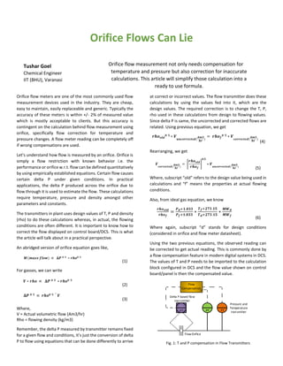
  • 1. Orifice Flows Can Lie Orifice flow measurement not only needs compensation for temperature and pressure but also correction for inaccurate calculations. This article will simplify those calculation into a ready to use formula. Orifice flow meters are one of the most commonly used flow measurement devices used in the industry. They are cheap, easy to maintain, easily replaceable and generic. Typically the accuracy of these meters is within +/- 2% of measured value which is mostly acceptable to clients. But this accuracy is contingent on the calculation behind flow measurement using orifice, specifically flow correction for temperature and pressure changes. A flow meter reading can be completely off if wrong compensations are used. Let’s understand how flow is measured by an orifice. Orifice is simply a flow restriction with known behavior i.e. the performance or orifice w.r.t. flow can be defined quantitatively by using empirically established equations. Certain flow causes certain delta P under given conditions. In practical applications, the delta P produced across the orifice due to flow through it is used to estimate the flow. These calculations require temperature, pressure and density amongst other parameters and constants. The transmitters in plant uses design values of T, P and density (rho) to do these calculations whereas, in actual, the flowing conditions are often different. It is important to know how to correct the flow displayed on control board/DCS. This is what the article will talk about in a practical perspective. An abridged version of orifice equation goes like, (1) For gasses, we can write (2) (3) Where, V = Actual volumetric flow (Am3/hr) Rho = flowing density (kg/m3) Remember, the delta P measured by transmitter remains fixed for a given flow and conditions, it’s just the conversion of delta P to flow using equations that can be done differently to arrive at correct or incorrect values. The flow transmitter does these calculations by using the values fed into it, which are the design values. The required correction is to change the T, P, rho used in these calculations from design to flowing values. Since delta P is same, the uncorrected and corrected flows are related. Using previous equation, we get (4) Rearranging, we get (5) Where, subscript “old” refers to the design value being used in calculations and “f” means the properties at actual flowing conditions. Also, from ideal gas equation, we know (6) Where again, subscript “d” stands for design conditions (considered in orifice and flow meter datasheet). Using the two previous equations, the observed reading can be corrected to get actual reading. This is commonly done by a flow compensation feature in modern digital systems in DCS. The values of T and P needs to be imported to the calculation block configured in DCS and the flow value shown on control board/panel is then the compensated value. F Flow Compensation PT TTFT Flow Orifice Delta P based flow transmitter Pressure and Temperature transmitter Fig. 1: T and P compensation in Flow Transmitters Tushar Goel Chemical Engineer IIT (BHU), Varanasi
  • 2. Above shown configuration is one of the most commonly used flow compensation system at the battery limit flows of plant for accurate measurement of import and export streams. Actual volumetric flow vs Normal volumetric flow But this is just the beginning of corrections and compensations. Many clients prefer their flow measurements represented on a standard or normal conditions for easy comparison. This makes it easy to communicate the flow values by eliminating the need to tell P and T every time the flow value is reported. Typically the normal conditions are 0 deg C and 1 atm i.e. the flow reported in Nm3/hr is always at 273.15 K and 1.033 kg/cm2a. where, Flowing Pressure (Pf) and Flowing Temperature (Tf) are expressed in units of kg/cm2 (g) and °C. As one can see, once again the use of T, P arises to covert the flows from actual to normal conditions. If flowing conditions (Tf, Pf) are not provided to the calculation block, design conditions will be used by default, which is again bound to give wrong flow values. Correcting the uncorrected flows represented at normal conditions (Nm3/hr) One of the tedious tasks for a process engineer is to correct the uncompensated and uncorrected DCS reading into correct flow measurements. The calculation to convert Am3/hr to Nm3/hr was done by DCS by using design T and P while actually the flowing T and P are different. This needs to be corrected. Below flowchart explain the process of doing the calculations. Let us consider an example: Td = 10 deg C Pd = 2.2 kg/cm2g Rhod = 3.8597 kg/m3 MWd = 28.03 Tf = 20 deg C (measured by instrument) Pf = 2.7 kg/cm2g (measured by instrument) MWf = 22.8 (as provided by laboratory sample analysis) Flow as shown on DCS screen = 4000 Nm3/hr which is uncorrected and uncompensated. Converting the Nm3/hr to Am3/hr (uncorrected) = 4000 ∗ ( 1.033 1.033+2.2 ) ∗ ( 10+273.15 273.15 ) = 1324.86 Am3/hr (uncorrected) Now, we know (7) 𝑟ℎ𝑜_𝑜𝑙𝑑 𝑟ℎ𝑜_𝑛𝑒𝑤 = (2.2 + 1.033) 2.7 + 1.033 ∗ 20 + 273.15 10 + 273.15 ∗ ( 28.03 22.8 ) So we get, rhoold/rhonew = 1.104717 Now using the correction formula from eq. (5) And finally converting the Am3/hr to Nm3/hr based on actual flowing conditions, we get The correct flow is 4688.83 vs 4000 Nm3/hr as shown on DCS screen which equals to 17% error in measurement. The above calculations are summarized in the following single formula for correction of gas flows reported in Nm3/hr: Convert the measured Nm3/hr to Am3/hr based on Design conditions The DCS system has incorporated a calculation which converts the Am3/hr to Nm3/hr based on DESIGN CONDITIONS. But the conditions have changed to FLOWING CONDITIONS, so you would like to undo those calculations. Correct this Am3/hr by using the orifice correlation. Convert the Corrected Am3/hr back to Nm3/hr based on actual flowing conditions The Am3/hr that we got in previous step was calculated based on ΔP observed across orifice. The conversion of ΔP to Am3/hr also involves T & P and Mol. Wt. Since these values have changed, we need to correct this conversion of ΔP to flow. Once the corrected Am3/hr based on actual MW, T and P is obtained, we need to convert it to Nm3/hr. This conversion has to be done based on FLOWING CONDITIONS and not the design conditions.