Multivariable Flow Measurement
•Download as PPS, PDF•
4 likes•3,143 views

I have prepared this presentation after successful commissioning of two such Multivariable Transmitters with 1595 Conditioning Orifice, used to measure raw gas of two trains in OMV (Pakistan) Exploration GmbH. Sawan gas processing plant,

More Related Content
What's hot
What's hot (20)
Viewers also liked
Viewers also liked (20)
Similar to Multivariable Flow Measurement
Similar to Multivariable Flow Measurement (20)
More from Mustafa Ali
Multivariable Flow Measurement
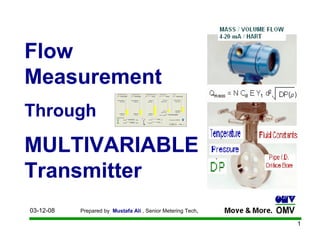
- 1. Flow Measurement Through MULTIVARIABLE Transmitter
- 2. Conventional Flow Calculation FLOW COMPUTER / DCS
- 3. Traditional DP TRANSMITTER, DP flow has been calculated in a DCS or flow computer using a simplified mass flow equation. In simplified DP mass flow measurements, a constant is used to represent many of the terms in the flow calculation The constant combines unit conversion factor, velocity of approach factor, gas expansion factor, and discharge coefficient. The simplified flow equation cannot compensate for changes in these terms, resulting in unrecorded errors in the calculated flow rate. Conventional Flow Calculation FLOW COMPUTER / DCS
- 4. Enhance Flow Calculation MULTIVARIABLE TRANSMITTER
- 5. Qmass = Mass flow N = units conversion factor Cd = discharge coefficient E = velocity of approach factor Y1 = gas expansion factor d2 = bore of differential producer DP = Differential pressure p = density The MULTIVARIABLE TRANSMITTER (3095MV) provides the greatest DP flow accuracy over the widest operating range by dynamically calculating all flow equation coefficients real time, including discharge coefficients, velocity of approach factor, thermal expansion effects, and density. This fully compensated flow equation reduces the sources of traditional DP flow uncertainty, thereby providing a more accurate flow calculation. It uses a fully compensated equation from mass flow through any differential producer Enhance Flow Calculation MULTIVARIABLE TRANSMITTER
- 6. How Does MULTIVARIABLE Tx3095MV Calculate Mass Flow? Using the EA Software the user enters the process fluid (EA database already knows molecular weight, isentropic exponent, and constants), primary element type and size, and pressure and temperature operating conditions. The Model 3095MV measures the static pressure, differential pressure, and process temperature. The internal flow computer dynamically calculates all flow equation coefficients in real time including: discharge coefficient, velocity of approach factor, thermal expansion effects, and density Result is the greatest DP flow accuracy over the widest operating range!
- 8. Advantages of MULTIVARIABLE TRANSMITTER 3095MV Primary element and fluid flexibility Provides flow computer functionally in a single, compact package. Dynamically Compensated mass flow 1% of mass flow rate accuracy over 10:1 flow range Four measurements (Qm, DP, P, T) in one device providing real-time data to perform mass and heat balances across process units. Output options 4-20 mA / HART based , Configuration of Pressure, Temp & DP through HART , Easy to configure with AMS & Engineering Assistant (EA) software
- 9. The innovative technology and design of the Conditioning Orifice Plate enables multiple benefits without compromising performance. The Conditioning Orifice Plate follows the discharge coefficient of the ISO 5167-2:2003(E) Conditioning Orifice Plate rivals the performance of the standard orifice plates while virtually eliminating straight pipe run requirements. With sufficient straight run, the accuracy curve of the Conditioning Orifice Plate would follow the ISO 5167 standard. Rosemout 1595 Conditioning Orifice Plate
- 10. Conditioning Orifice Plate Technology is based on the same Bernoulli streamline energy equation and as a result follows the same Discharge Coefficient versus Reynolds Number relationship as standard orifice plates. Installation in short straight pipe run, tight fit applications. Improved performance in wet gas applications by allowing condensate to pass and preventing the “damming” affect suffered by standard orifice plates. None of the three standards provide allowances for drain vent holes in the orifice plate. Rosemout 1595 Conditioning Orifice Plate
- 11. Rosemout 1595 Conditioning Orifice Plate
- 12. Rosemout 1595 Conditioning Orifice Plate
- 13. Configuration with HART Communicator Configuration with AMS / Engineering Assistant (EA) software
- 14. Configuration with AMS / Engineering Assistant (EA) software
- 15. Process parameters Display Configuration with AMS / Engineering Assistant (EA) software
- 16. Configuration with AMS / Engineering Assistant (EA) software Flow configuration wizard
- 17. Configuration with AMS / Engineering Assistant (EA) software
- 18. Configuration with AMS / Engineering Assistant (EA) software Gas Calculation Method Selection
- 19. Configuration with AMS / Engineering Assistant (EA) software Gas Composition for Density measurement
- 20. Configuration with AMS / Engineering Assistant (EA) software Primary Element 1595 Conditioning Orifice Plate selection
- 21. Configuration with AMS / Engineering Assistant (EA) software Operating envelope (Pressure & Temperature)
- 22. Configuration with AMS / Engineering Assistant (EA) software Auto Compressibility Calculation for corrected volume
- 23. Configuration with AMS / Engineering Assistant (EA) software Configuration properties
- 24. Configuration with AMS / Engineering Assistant (EA) software Configuration properties
- 25. Configuration with AMS / Engineering Assistant (EA) software Configuration properties
- 26. Configuration with AMS / Engineering Assistant (EA) software Configuration properties
- 27. Configuration with AMS / Engineering Assistant (EA) software Configuration properties
- 28. Configuration with AMS / Engineering Assistant (EA) software Configuration properties
- 29. Configuration with AMS / Engineering Assistant (EA) software Configuration properties
- 30. Configuration with AMS / Engineering Assistant (EA) software Configuration properties
- 31. Configuration with AMS / Engineering Assistant (EA) software Configuration properties
- 32. Configuration with AMS / Engineering Assistant (EA) software Configuration properties
- 33. Configuration with AMS / Engineering Assistant (EA) software Configuration properties
- 34. Configuration with AMS / Engineering Assistant (EA) software Configuration properties
- 35. Configuration with AMS / Engineering Assistant (EA) software Configuration properties
- 36. Configuration with AMS / Engineering Assistant (EA) software Configuration properties
- 37. Configuration with AMS / Engineering Assistant (EA) software Configuration properties
- 38. Configuration with AMS / Engineering Assistant (EA) software Online Validation on DP, Pressure & Temperature
- 39. Configuration with AMS / Engineering Assistant (EA) software Parameters display
- 40. THANK YOU
- 41. Q A QUESTION ANSWERS