Download to read offline
![Pointcut Rejuvenation:
Recovering Pointcut Expressions
in Evolving Aspect-Oriented Software
Raffi Khatchadourian, Member, IEEE, Phil Greenwood,
Awais Rashid, Member, IEEE, and Guoqing Xu
Abstract—Pointcut fragility is a well-documented problem in Aspect-Oriented Programming; changes to the base code can lead to join
points incorrectly falling in or out of the scope of pointcuts. In this paper, we present an automated approach that limits fragility
problems by providing mechanical assistance in pointcut maintenance. The approach is based on harnessing arbitrarily deep structural
commonalities between program elements corresponding to join points selected by a pointcut. The extracted patterns are then applied
to later versions to offer suggestions of new join points that may require inclusion. To illustrate that the motivation behind our proposal
is well founded, we first empirically establish that join points captured by a single pointcut typically portray a significant amount of
unique structural commonality by analyzing patterns extracted from 23 AspectJ programs. Then, we demonstrate the usefulness of our
technique by rejuvenating pointcuts in multiple versions of three of these programs. The results show that our parameterized heuristic
algorithm was able to accurately and automatically infer the majority of new join points in subsequent software versions that were not
captured by the original pointcuts.
Index Terms—Software development environments, software maintenance, software tools.
Ç
1 INTRODUCTION
ASPECT-ORIENTED Programming (AOP) [23] has emerged
to reduce the scattering and tangling of crosscutting
concern (CCC) implementations. This is achieved through
specifying that certain behavior (advice) should be
composed at specific (join) points during the execution of
the underlying program (base code). Join point sets are
described by pointcut expressions (PCEs), which are
predicate-like expressions over various characteristics of
“events” that occur during the program’s execution. In
AspectJ [22], such characteristics may include calls to
certain methods, accesses to particular fields, and mod-
ifications to the runtime stack.
Consider an example PCE execution(* m*(..)) that selects
the execution of all methods whose name begins with m,
taking any number and type of arguments and returning
any type of value. Suppose that in one base code version the
above PCE selects the correct set of join points in which a
CCC applies. As the software evolves, this set of join points
may change as well. We say that a PCE is robust if in its
unaltered form it is able to continue to capture the correct set
of join points in future base code versions. Thus, the PCE
given above would be considered robust if the set of join
points in which the CCC applies always corresponded to
executions of methods whose name begins with m, taking
any number and type of arguments, and so forth. However,
with the requirements of typical software tending to change
over time, the corresponding source code may undergo
many alterations to accommodate such change, including
the addition of new elements in which existing CCCs should
also apply. Without a priori knowledge of future main-
tenance changes and additions, creating robust PCEs is a
daunting task. As such, there may easily exist situations
where the PCE itself must evolve along with the base code;
in these cases, we say that the PCE is fragile. Hence, the
fragile pointcut problem [25] manifests itself in such circum-
stances where join points incorrectly fall in or out of the
scope of PCEs.
Several approaches aim to combat this problem by
proposing new pointcut languages with improved expres-
siveness (e.g., [6], [24], [31], [36], [37]), limiting the scope of
where advice may apply through more clearly defined
interfaces (e.g., [14]), or enforcing structural and/or
behavioral constraints on advice application (e.g., [13],
[19], [40]). Yet others make points where advice may apply
more explicit in the base code [17], or remove PCEs
altogether [33]. However, each of these tend to require
some level of anticipation and, consequently, when using
PCEs there may nevertheless exist situations where PCEs
must be manually updated to capture new join points as the
software evolves.
Programmer-defined source code annotations can also be
used to “mark” relevant locations in the source code where a
CCC applies. PCEs then use these annotations to accurately
select the appropriate join points. If used properly, i.e., if all
642 IEEE TRANSACTIONS ON SOFTWARE ENGINEERING, VOL. 38, NO. 3, MAY/JUNE 2012
. R. Khatchadourian and G. Xu are with the Department of Computer
Science and Engineering, Ohio State University, Columbus, OH 43210.
E-mail: {khatchad, xug}@cse.ohio-state.edu.
. P. Greenwood and A. Rashid are with Computing Department, Lancaster
University, Lancaster LA1 4WA, United Kingdom.
E-mail: {greenwop, awais}@comp.lancs.ac.uk.
Manuscript received 27 Feb. 2010; revised 23 Aug. 2010; accepted 26 Jan.
2011; published online 7 Feb. 2011.
Recommended for acceptance by T. Tamai.
For information on obtaining reprints of this article, please send e-mail to:
tse@computer.org, and reference IEEECS Log Number TSE-2010-02-0054.
Digital Object Identifier no. 10.1109/TSE.2011.21.
0098-5589/12/$31.00 ß 2012 IEEE Published by the IEEE Computer Society](https://image.slidesharecdn.com/pointcutrejuvenation-130427101951-phpapp02/85/Pointcut-rejuvenation-1-320.jpg)
![Pointcut Rejuvenation:
Recovering Pointcut Expressions
in Evolving Aspect-Oriented Software
Raffi Khatchadourian, Member, IEEE, Phil Greenwood,
Awais Rashid, Member, IEEE, and Guoqing Xu
Abstract—Pointcut fragility is a well-documented problem in Aspect-Oriented Programming; changes to the base code can lead to join
points incorrectly falling in or out of the scope of pointcuts. In this paper, we present an automated approach that limits fragility
problems by providing mechanical assistance in pointcut maintenance. The approach is based on harnessing arbitrarily deep structural
commonalities between program elements corresponding to join points selected by a pointcut. The extracted patterns are then applied
to later versions to offer suggestions of new join points that may require inclusion. To illustrate that the motivation behind our proposal
is well founded, we first empirically establish that join points captured by a single pointcut typically portray a significant amount of
unique structural commonality by analyzing patterns extracted from 23 AspectJ programs. Then, we demonstrate the usefulness of our
technique by rejuvenating pointcuts in multiple versions of three of these programs. The results show that our parameterized heuristic
algorithm was able to accurately and automatically infer the majority of new join points in subsequent software versions that were not
captured by the original pointcuts.
Index Terms—Software development environments, software maintenance, software tools.
Ç
1 INTRODUCTION
ASPECT-ORIENTED Programming (AOP) [23] has emerged
to reduce the scattering and tangling of crosscutting
concern (CCC) implementations. This is achieved through
specifying that certain behavior (advice) should be
composed at specific (join) points during the execution of
the underlying program (base code). Join point sets are
described by pointcut expressions (PCEs), which are
predicate-like expressions over various characteristics of
“events” that occur during the program’s execution. In
AspectJ [22], such characteristics may include calls to
certain methods, accesses to particular fields, and mod-
ifications to the runtime stack.
Consider an example PCE execution(* m*(..)) that selects
the execution of all methods whose name begins with m,
taking any number and type of arguments and returning
any type of value. Suppose that in one base code version the
above PCE selects the correct set of join points in which a
CCC applies. As the software evolves, this set of join points
may change as well. We say that a PCE is robust if in its
unaltered form it is able to continue to capture the correct set
of join points in future base code versions. Thus, the PCE
given above would be considered robust if the set of join
points in which the CCC applies always corresponded to
executions of methods whose name begins with m, taking
any number and type of arguments, and so forth. However,
with the requirements of typical software tending to change
over time, the corresponding source code may undergo
many alterations to accommodate such change, including
the addition of new elements in which existing CCCs should
also apply. Without a priori knowledge of future main-
tenance changes and additions, creating robust PCEs is a
daunting task. As such, there may easily exist situations
where the PCE itself must evolve along with the base code;
in these cases, we say that the PCE is fragile. Hence, the
fragile pointcut problem [25] manifests itself in such circum-
stances where join points incorrectly fall in or out of the
scope of PCEs.
Several approaches aim to combat this problem by
proposing new pointcut languages with improved expres-
siveness (e.g., [6], [24], [31], [36], [37]), limiting the scope of
where advice may apply through more clearly defined
interfaces (e.g., [14]), or enforcing structural and/or
behavioral constraints on advice application (e.g., [13],
[19], [40]). Yet others make points where advice may apply
more explicit in the base code [17], or remove PCEs
altogether [33]. However, each of these tend to require
some level of anticipation and, consequently, when using
PCEs there may nevertheless exist situations where PCEs
must be manually updated to capture new join points as the
software evolves.
Programmer-defined source code annotations can also be
used to “mark” relevant locations in the source code where a
CCC applies. PCEs then use these annotations to accurately
select the appropriate join points. If used properly, i.e., if all
642 IEEE TRANSACTIONS ON SOFTWARE ENGINEERING, VOL. 38, NO. 3, MAY/JUNE 2012
. R. Khatchadourian and G. Xu are with the Department of Computer
Science and Engineering, Ohio State University, Columbus, OH 43210.
E-mail: {khatchad, xug}@cse.ohio-state.edu.
. P. Greenwood and A. Rashid are with Computing Department, Lancaster
University, Lancaster LA1 4WA, United Kingdom.
E-mail: {greenwop, awais}@comp.lancs.ac.uk.
Manuscript received 27 Feb. 2010; revised 23 Aug. 2010; accepted 26 Jan.
2011; published online 7 Feb. 2011.
Recommended for acceptance by T. Tamai.
For information on obtaining reprints of this article, please send e-mail to:
tse@computer.org, and reference IEEECS Log Number TSE-2010-02-0054.
Digital Object Identifier no. 10.1109/TSE.2011.21.
0098-5589/12/$31.00 ß 2012 IEEE Published by the IEEE Computer Society](https://image.slidesharecdn.com/pointcutrejuvenation-130427101951-phpapp02/75/Pointcut-rejuvenation-1-2048.jpg)
![(false negative) error rates of 18 and 16 percent,
respectively.
3. Expression recovery. To ensure the applicability and
practicality of our approach, we implemented our
algorithm as an Eclipse (http://eclipse.org) IDE
plug-in and evaluated its usefulness by rejuvenating
PCEs in multiple versions of three of the aforemen-
tioned programs, which were of varying sizes and
domains and representative of typical AO software.
We found that, in exploiting the extracted patterns,
our tool was able to accurately and automatically
infer 90 percent of new join points that were selected
by PCEs in subsequent software versions that were
not selected by the original PCE, with a standard
deviation of 24 percent. This demonstrates that the
approach is indeed useful in alleviating the burden of
recovering PCEs upon base-code modifications that
took place in our subject programs, and the results
advance the state of the art in automated tool support
for coping with the evolution of AO programs.
A brief introduction of this work originally appeared in
[20], and a demonstration of our preliminary tool, along
with details of the implementation, appeared in [21]. In this
paper, we fully describe our complete approach, which has
been built upon the aforementioned previous work. This
complete approach includes thoroughly developed ideas
that have been incorporated into our initial algorithm. We
also present a new dimension of our experimental results to
comprehensively and accurately assess the overall useful-
ness of our approach.
The remainder of this paper is organized as follows:
Section 2 presents a motivating example that features a
fragile PCE. Section 3 highlights the key algorithmic facets
of our approach, while Section 4 discusses the details of our
implementation and evaluation. In Section 5, we compare
our proposal with related work and explore future work, as
well as conclude, in Section 6.
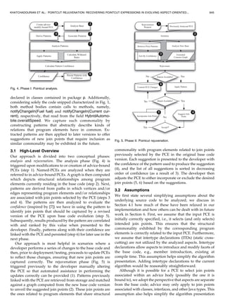
2 POINTCUT FRAGILITY EXAMPLE
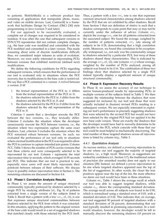
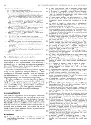
Fig. 1 shows an example AspectJ code snippet for a
hypothetical drive-by-wire programming of an all-wheel
drive, hybrid vehicle (line 2) which draws power from two
different sources, namely, a diesel engine (line 25) and an
electric motor (line 30), both of which contribute to the
overall speed (line 3).1
Fuel is distributed to the engine via
KHATCHADOURIAN ET AL.: POINTCUT REJUVENATION: RECOVERING POINTCUT EXPRESSIONS IN EVOLVING ASPECT-ORIENTED... 643
1. This example was inspired by one of the authors’ work at the Center
for Automotive Research (CAR) at Ohio State University.](https://image.slidesharecdn.com/pointcutrejuvenation-130427101951-phpapp02/85/Pointcut-rejuvenation-3-320.jpg)
![declared in classes contained in package p. Additionally,
considering solely the code snipped characterized in Fig. 1,
both method bodies contain calls to methods, namely,
notifyChangeIn(Fuel fuel) and notifyChangeIn(Current cur-
rent), respectively, that read from the field HybridAutomo-
bile.overallSpeed. We capture such commonality by
constructing patterns that abstractly describe kinds of
relations that program elements have in common. Ex-
tracted patterns are then applied to later versions to offer
suggestions of new join points that require inclusion as
similar commonality may be exhibited in the future.
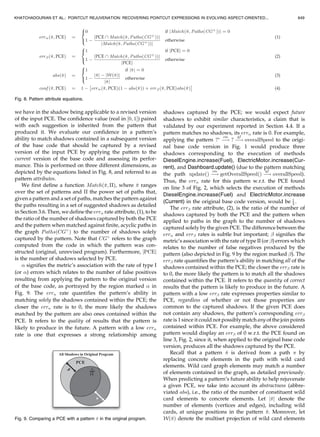
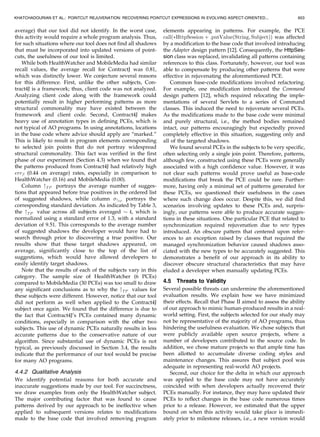
3.1 High-Level Overview
Our approach is divided into two conceptual phases:
analysis and rejuvenation. The analysis phase (Fig. 4) is
triggered upon modifications to or creation of advice-bound
PCEs (step 1). Named-PCEs are analyzed when they are
referred to in advice-bound PCEs. A graph is then computed
which depicts structural relationships among program
elements currently residing in the base code (step 2). Next,
patterns are derived from paths in which vertices and/or
edges representing program elements and/or relationships
are associated with join points selected by the PCE (steps 3
and 4). The patterns are then analyzed to evaluate the
confidence (inspired by [7]) we have in using the pattern to
identify join points that should be captured by a revised
version of the PCE upon base code evolution (step 5).
Subsequently, results produced by the pattern are correlated
with and ranked by this value when presented to the
developer. Finally, patterns along with their confidence are
linked with the PCE and persisted (step 6) for later use in the
next phase.
Our approach is most helpful in scenarios where a
developer performs a series of changes to the base code and
then, prior to deployment/testing, proceeds to update PCEs
to reflect those changes, ensuring that new join points are
captured correctly. The rejuvenation phase (Fig. 5) is
triggered previously to the developer manually altering
the PCE so that automated assistance in performing the
updates correctly can be provided (1). Patterns previously
linked with the PCE are retrieved from storage and matched
against a graph computed from the new base code version
to unveil the suggested join points (2). These join points are
the ones related to program elements that share structural
commonality with program elements related to join points
previously selected by the PCE in the original base code
version. Each suggestion is presented to the developer with
the confidence of the pattern used to produce the suggestion
(4), and the list of all suggestions is sorted in decreasing
order of confidence (as a result of 3). The developer then
adjusts the PCE to either incorporate or exclude the desired
join points (5, 6) based on the suggestions.
3.2 Assumptions
We first state several simplifying assumptions about the
underlying source code to be analyzed; we discuss in
Section 4.1 how much of these have been relaxed in our
implementation and how others can be dealt with in future
work in Section 6. First, we assume that the input PCE is
initially correctly specified, i.e., it selects (and only selects)
intended join points. This ensures that the structural
commonality exhibited by the corresponding program
elements is correctly related to the input PCE. Furthermore,
we assume that intertype declarations (ITDs) (static cross-
cutting) are not utilized by the analyzed aspects. Intertype
declarations allow aspects to introduce and modify facets of
the base code, e.g., member introduction, existing at
compile time. This assumption helps simplify the algorithm
presentation. Adding intertype declarations to the current
algorithm would be reasonably straightforward.
Although it is possible for a PCE to select join points
associated within an advice body (possibly the one it is
bound to), we adopt the perspective that aspects are separate
from the base code; advice may only apply to join points
associated with classes, interfaces, and other Java types. This
assumption also helps simplify the algorithm presentation
KHATCHADOURIAN ET AL.: POINTCUT REJUVENATION: RECOVERING POINTCUT EXPRESSIONS IN EVOLVING ASPECT-ORIENTED... 645
Fig. 4. Phase I: Pointcut analysis.
Fig. 5. Phase II: Pointcut rejuvenation.](https://image.slidesharecdn.com/pointcutrejuvenation-130427101951-phpapp02/85/Pointcut-rejuvenation-5-320.jpg)
![since it reduces both the kinds of entities and relations
between the entities existing in the input program that need
to be considered. Moreover, it frees us from resolving the
targets of proceed calls, which may exist in around advice.
We discuss adding advice bodies in Section 6. Last, we
assume that we can accurately resolve the declaration of the
advice a PCE is bound to across varying versions of the
software. This may be invalidated via the use of refactorings,
e.g., member relocation, being applied in between software
versions. Section 6 discusses plans for how our approach can
be made to cope with this issue.
3.3 Concern Graphs
To abstract the details of the underlying source code, a
representation of the program is first built using an
adaptation of a concern graph [35]. Concern graphs have
been used in previous work [34] to discover, describe, and
track concerns in evolving source code as they allow for
succinct program representations. We have chosen to use
concern graphs since they include information about the
structure of programs, and we are interested in unveiling
underlying structural patterns. We extended concern graphs
with several elements found in current Java languages, e.g.,
annotations, and adapted them for use with AOP.
We specify an extended concern graph CGþ
to be a labeled
multidigraph consisting of a 4-tuple CGþ
¼ ðV ; E; R; ‘Þ. The
vertices V represent program elements contained within the
analyzed program, specifically, packages, classes, interfaces,
enumeration types, annotations, methods, and fields. We do
not consider local variables and other parameters in our
analysis as crosscutting concerns tend to crosscut a larger
granularity of program elements. E is a multiset of directed
edges that connect vertices in V depending on various
relations that may hold between them as depicted in the
source code. For example, HybridAutomobile and over-
allSpeed (Fig. 1) are related in that the class HybridAutomobile
declares the field overallSpeed. In this case, there would exist
an edge connecting the vertex that represents HybridAuto-
mobile to the vertex representing overallSpeed. R is the set of
all such (binary) relations that we consider. Since two vertices
may berelated in several ways, i.e., they satisfy more than one
relation, there may exist multiple edges between them. As
such, ‘ : E ! R serves as a labeling function that distin-
guishes edges by labeling them with the satisfied relations.
Fig. 6 portrays a subset of the graph computed from the
example given in Section 2.
Table 1 portrays the complete set of binary relations that
we consider as well as the program entity types in which
they relate. Either of these relations may hold in a structural
sense, e.g., field declarations, or possibly during a particular
execution of the program, e.g., method calls. Section 4.1
discusses how we conservatively approximated the truth
value of these relations in our implementation by using
exclusively static information, i.e., through examination of
the program text, while Section 6 touches upon future work
which could result in a more accurate approximation. Many
kinds of relations may be formulated; however, we mainly
focus on popular relations as used in previous work [5], [7],
[35], with the addition of relations useful for AO languages,
e.g., Annotates. Section 4 reports on the appropriateness of
using such relations for PCE rejuvenation in AspectJ
programs; adding additional relations is discussed in
Section 6.
3.4 Concern Graph/Pointcut Association
The next step in our approach involves discovering graph
elements (vertices and edges) that represent program
elements corresponding to join points captured by the
input PCE so that patterns capturing commonality existing
between these elements can be later extracted. Recall that a
PCE describes a set of join points, which are well-defined
points in the program’s execution. Thus, a join point is very
much dynamic in nature. A join point shadow, conversely,
refers to base code corresponding to a join point, i.e., a point
in the program text where the compiler may actually
perform the weaving [29]. Whether the base code is advised
at that point is dependent on advice being applicable and
possible dynamic conditions being met. We treat a program
as consisting of a set of join point shadows that may or may
646 IEEE TRANSACTIONS ON SOFTWARE ENGINEERING, VOL. 38, NO. 3, MAY/JUNE 2012
Fig. 6. A graph subset computed from the example.
TABLE 1
Analyzed Program Entity Types and Relations](https://image.slidesharecdn.com/pointcutrejuvenation-130427101951-phpapp02/85/Pointcut-rejuvenation-6-320.jpg)
![not be currently advised. This definition differs slightly
from those typically given in the literature [16], [43] and
helps simplify the algorithm presentation. Moreover, we
treat a PCE as selecting a subset of these shadows, i.e., we
assume that the PCE is free of dynamic conditions. This
allows us to exploit solely static information in our analysis.
Section 4.1 discusses how our implementation conserva-
tively relaxes this assumption so that PCEs utilizing
dynamic conditions may nevertheless be used as input to
our tool. The evaluation results reported in Section 4.4
indicate that the impact of this limitation is minimal and
that our current approach can be useful. There is evidence
that suggests that most PCEs do not take advantage of
dynamic conditions [2].
Shadows corresponding to method declarations enable
method vertices, i.e., for a graph CGþ
¼ ðV ; E; R; ‘Þ we say
that a vertex v 2 V is associated with (or enabled w.r.t.) a
PCE iff v represents a method whose corresponding method
execution-join point shadow is selected by the PCE. Thus, a
vertex representing the method m would be considered
enabled w.r.t. a PCE that selects a method execution-join
point for m.
For a graph built from the example in Fig. 1, the vertices
representing the methods DieselEngine.increase(Fuel) and
ElectricMotor.increase(Current) would be considered en-
abled w.r.t. the PCE found on line 3, Fig. 2. The graph
subset in Fig. 6 illustrates this; the vertices representing
these methods are shaded.
While shadows corresponding to method declarations
enable method vertices, shadows corresponding to sites
(call-sites, field access, etc.) enable edges. We say that an
edge ðu; vÞ 2 E is enabled w.r.t. a PCE iff
. the edge is labeled as either a method call,
i.e., CallsMethodðu; vÞ holds, a field read, i.e.,
GetsFieldðu; vÞ holds, or a field write, i.e.,
SetsFieldðu; vÞ holds, and
. there exists a corresponding method call-, field get-,
or field set-join point shadow selected by the PCE
such that the called method, the read field, or the
written field, respectively, is the one represented by
vertex v, and the shadow resides within the body of
the method represented by vertex u.
For example, an edge representing a call from a method
m to a method n would be considered enabled w.r.t. a PCE
selecting a method call shadow for n originating in the body
(or in AspectJ terminology, withincode) of m. Note that the
difference between a method execution-join point and a
method call-join point is that in the former, the correspond-
ing shadow lies at the declaration of the invoked method,
while in the latter, it lies at the site of the method invocation,
i.e., the client code. Section 4.1 discusses how our
implementation leverages existing tool support to deduce
enabled graph elements.
3.5 Pattern Extraction
Once we associate (enable) graph elements with the input
PCE, (see Section 3.4), we analyze structural commonality
between these elements with the hope that future elements
whose shadows should be included in a new version of the
PCE may exhibit similar structural characteristics with a
particular level of confidence. Note that we only take
advantage of structural commonality between program
elements and not other kinds of commonality, e.g., string
similarity of method names. We are interested in exploiting
information pertaining to the structure and organization of
the base code when related to PCEs.
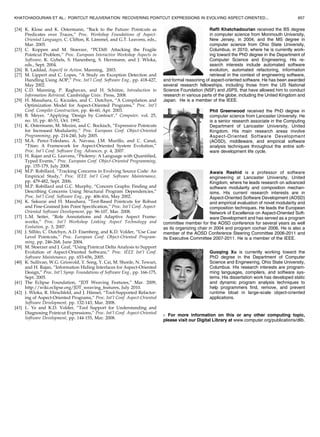
Recall that (increase(Fuel) and increase(Current)), whose
corresponding execution was selected by (execution(void
increase(Energy+))), both contained calls to (notifyChange-
In(Fuel) and notifyChangeIn(Current)), which read from
(overallSpeed). Deliberately, this information is expressed
by two paths (sequences of connected edges) increase(Fuel)
e
overallSpeed and increase(Energy) e
overallSpeed in
Fig. 6. We capture commonality associated with such graph
elements by extracting patterns from paths in which they are
contained. These patterns, which convey general “shapes”
(in terms of paths) of the graph surrounding the enabled
graph elements, i.e., graph elements representing program
elements corresponding to join point shadows selected by
the input PCE, will ultimately be applied to graphs
computed from subsequent versions to uncover new
elements displaying the captured commonality.
For each enabled (w.r.t. the input PCE) vertex v and edge
ðu; vÞ, we extract patterns from finite, acyclic paths of length
(in terms of edges) k passing through v and along ðu; vÞ,
respectively. The maximum analysis depth parameter k, an
input to the algorithm, controls tractability by restricting
the depth of satisfied relations analyzed and, conse-
quently, limits the length of the patterns derived. Section
4.2 discusses our choice for k in our evaluation. An
example of such a path when taking the enabled vertex
v ¼ increaseðFuelÞ a n d k ¼ 2 i s increaseFuelðFuelÞ cm
À!
notifyChangeInðFuelÞ gf
À! overallSpeed, where edge labels cm
and gf refer to the satisfied relations CallsMethod and
GetsField, respectively.
Intuitively, patterns are constructed from paths so that
paths matching the pattern are ones that share common
origins or sinks with the original path. Also, vertices in the
matching paths are connected via similar (in terms of labels)
edges as the vertices in the original path.
We consider two kinds of patterns, those derived from
enabled vertices, called vertex-based patterns, and those
from enabled edges, called edge-based patterns. A vertex-
based pattern is obtained from a path by replacing vertices
along the path with vertex wild cards. Vertex-based patterns
are used for suggesting method execution join points. An
edge-based pattern is obtained by not only replacing
vertices with vertex wild cards, but also a certain edge
with an edge wild card. Edge-based patterns are used for
suggesting site-based (e.g., call-site, field-set) join points.
The replacing edge wild card is related to the site-based
shadow to be suggested.
Vertex-based patterns will contain all but one (nonwild)
concrete vertex; this is the element representing the
common source or sink. Every edge in a vertex-based
pattern is concrete so that paths containing similarity
connected vertices can be matched with the pattern. There
are no edge wild cards in a vertex-based pattern. Edge-
based patterns are similar to vertex-based patterns with the
exception of the single edge wild card mentioned above.
KHATCHADOURIAN ET AL.: POINTCUT REJUVENATION: RECOVERING POINTCUT EXPRESSIONS IN EVOLVING ASPECT-ORIENTED... 647](https://image.slidesharecdn.com/pointcutrejuvenation-130427101951-phpapp02/85/Pointcut-rejuvenation-7-320.jpg)

The document discusses an approach to automatically recover pointcut expressions (PCEs) in evolving aspect-oriented software. It presents an algorithm that derives structural patterns from program elements selected by an original PCE. These patterns capture commonalities between the elements. The patterns are then applied to later versions to suggest new elements that may need to be included in an updated PCE. An evaluation of the approach on three programs found it was able to accurately infer 90% of new elements selected by PCEs in subsequent versions. The approach aims to assist developers in maintaining PCEs as software evolves.