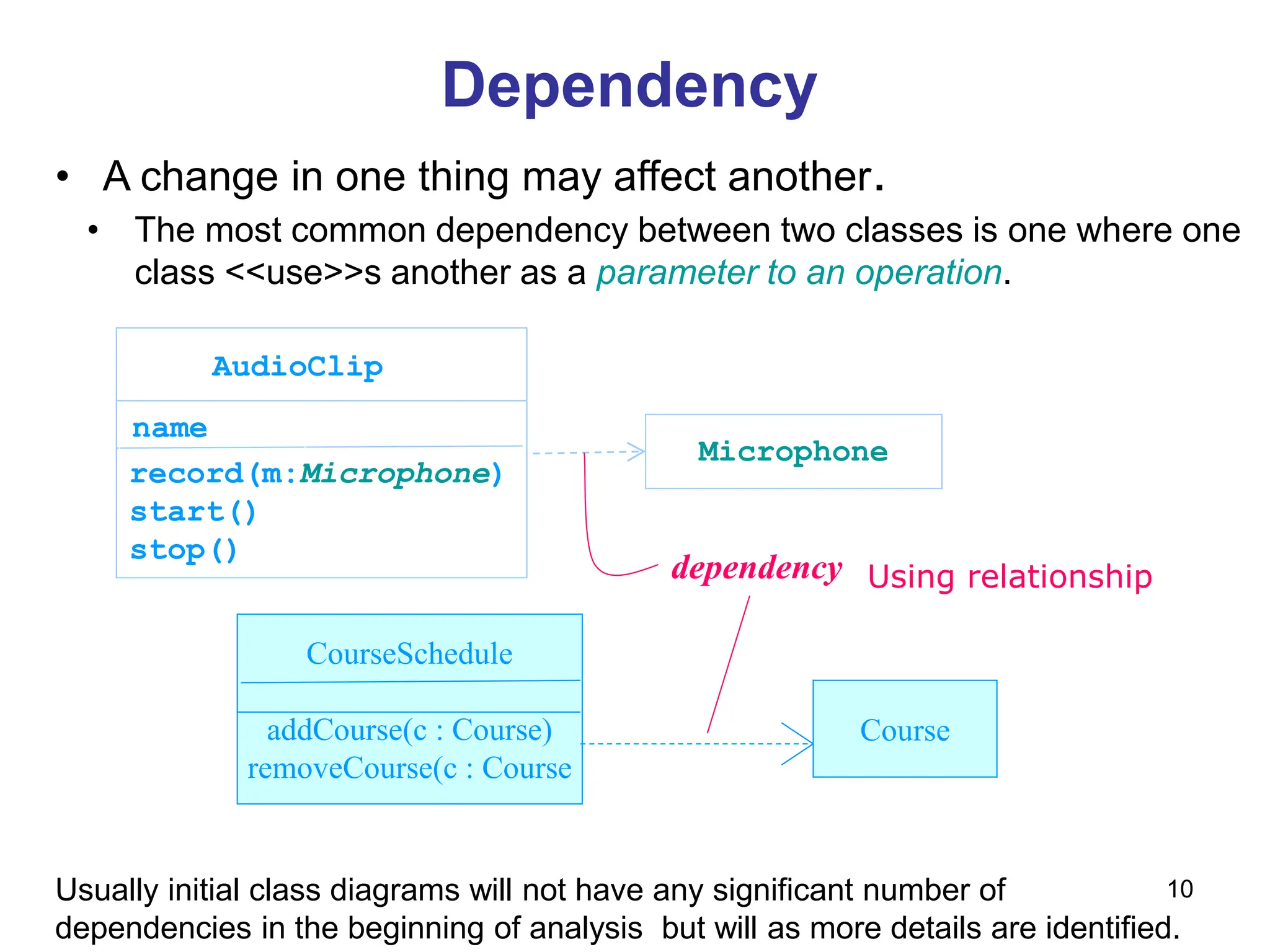
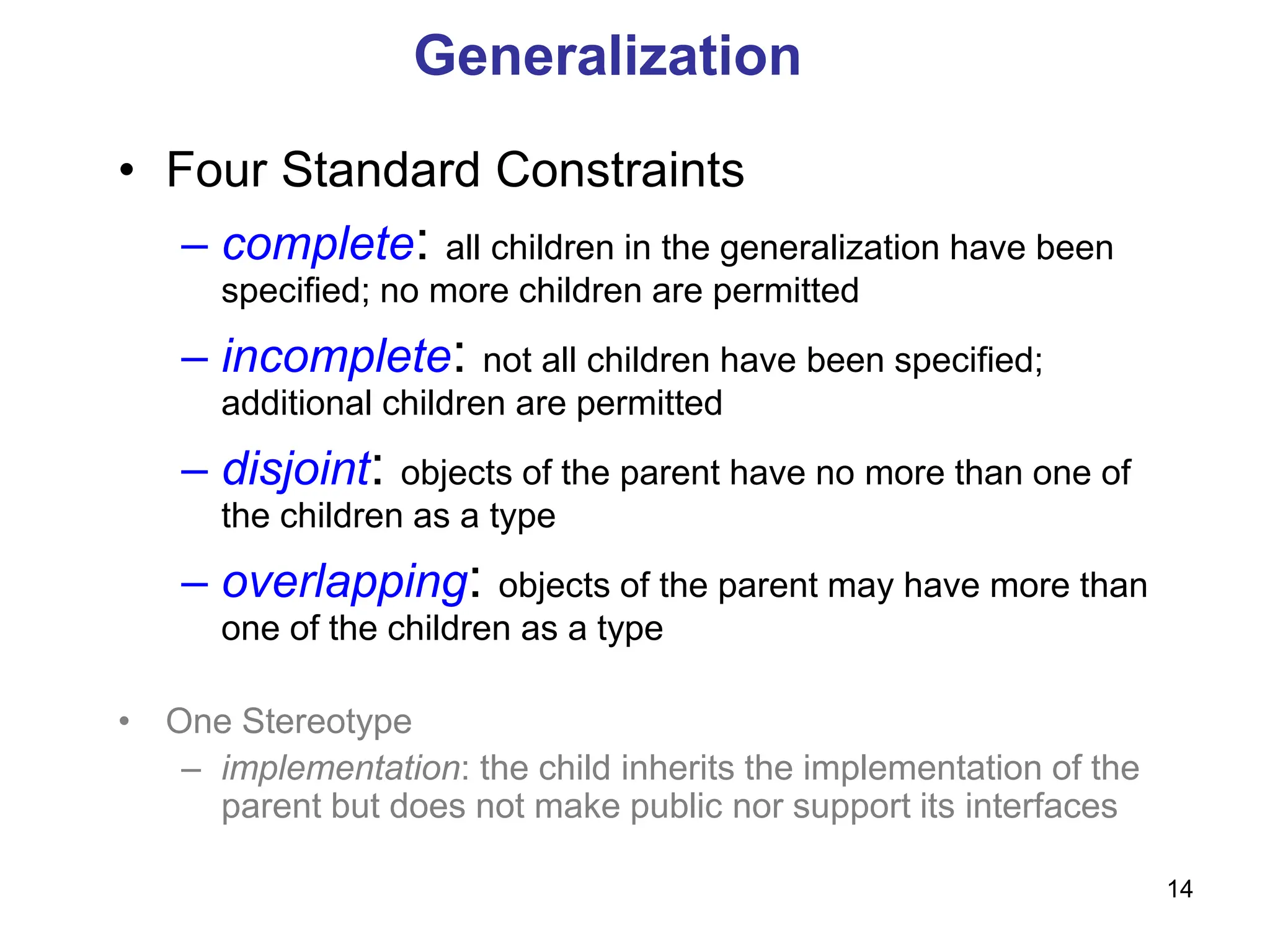
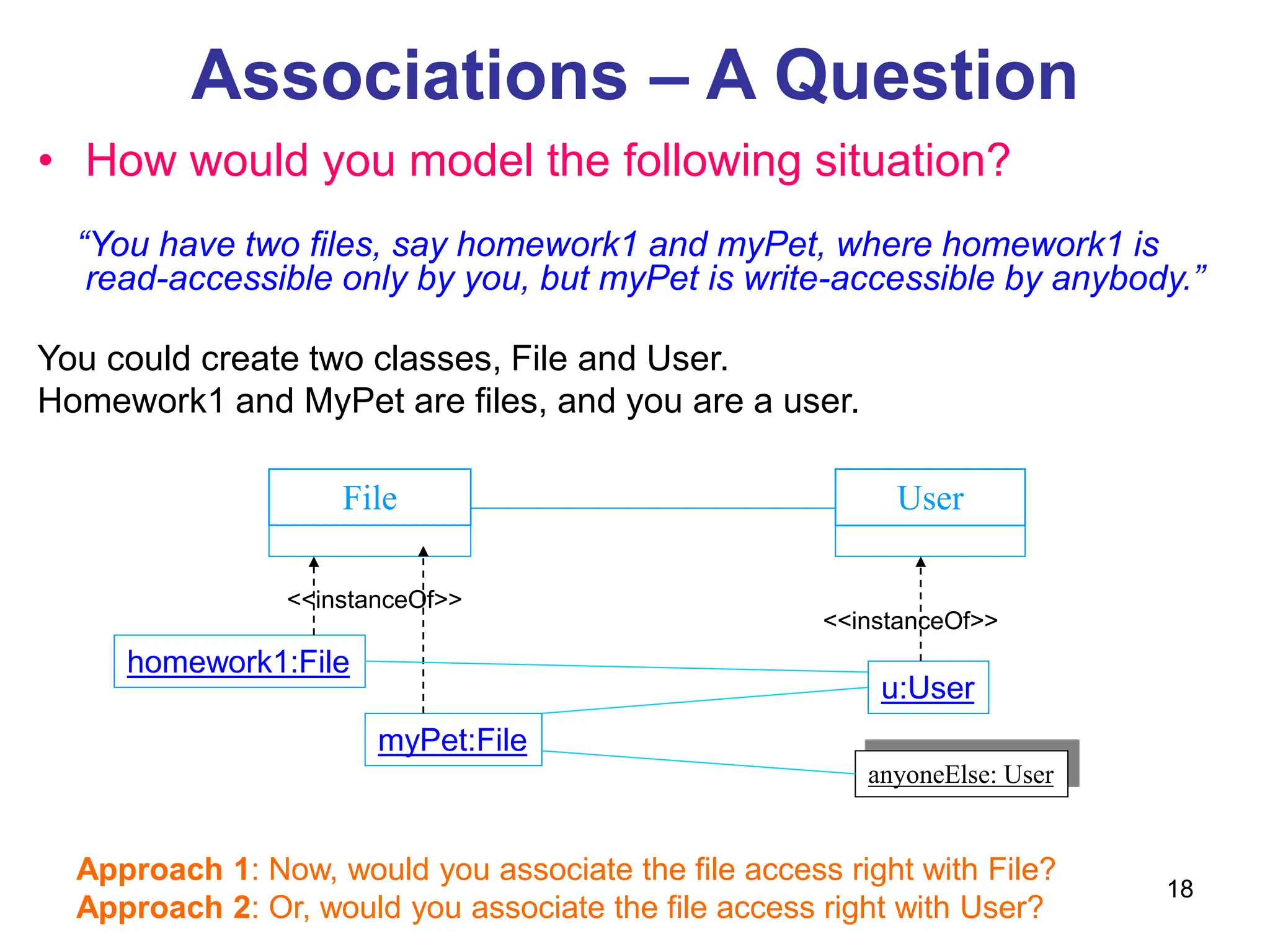
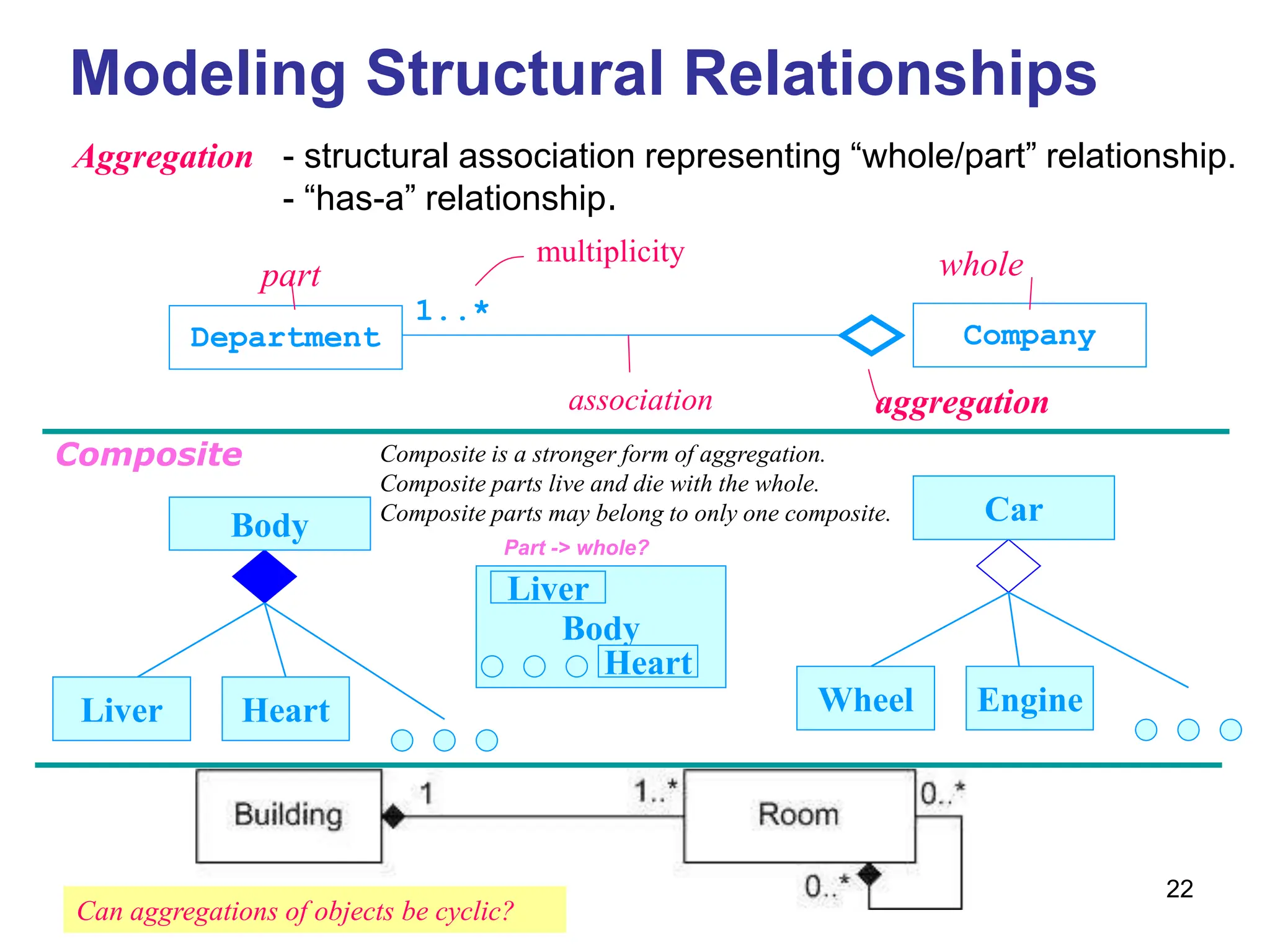
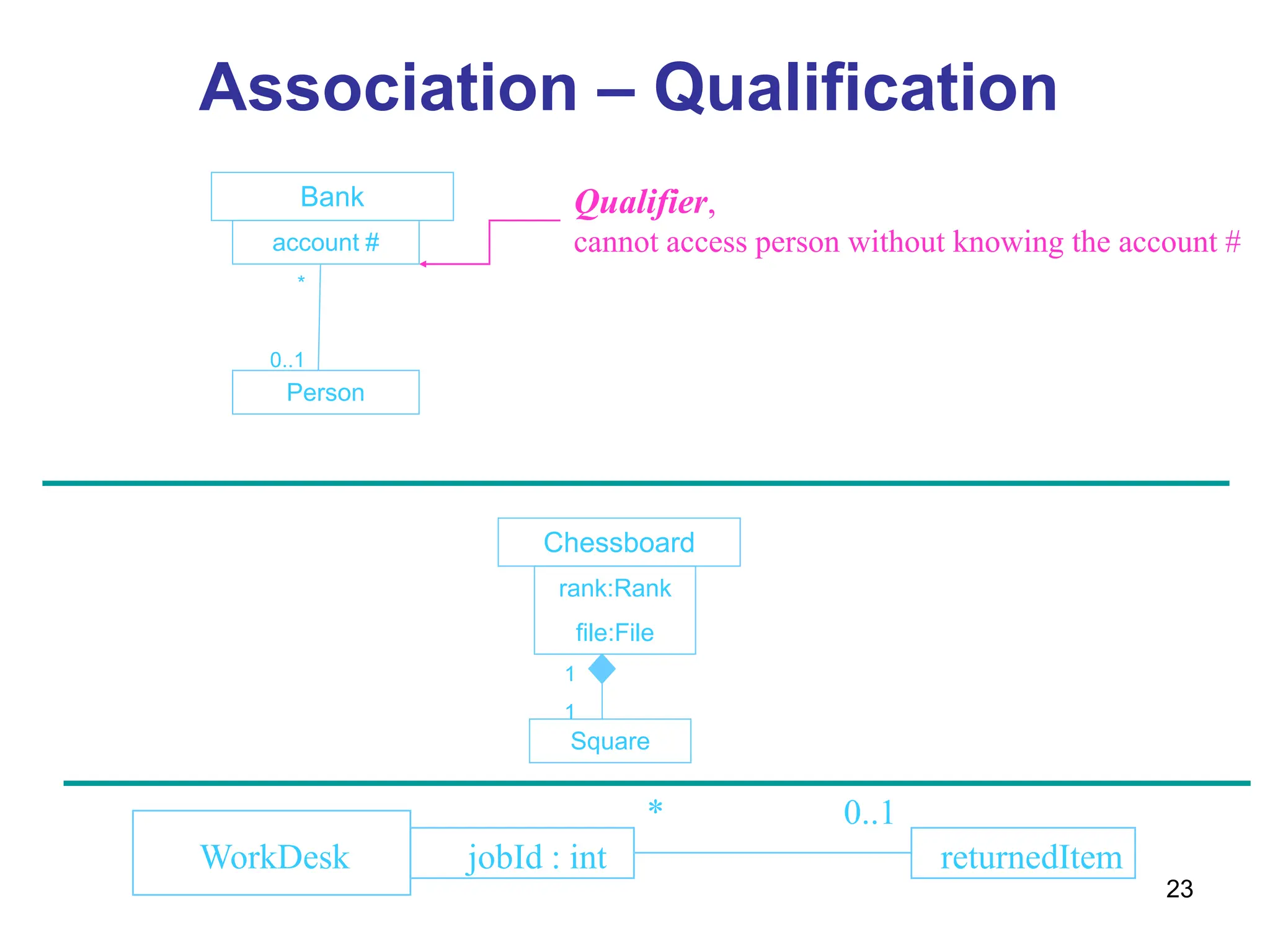
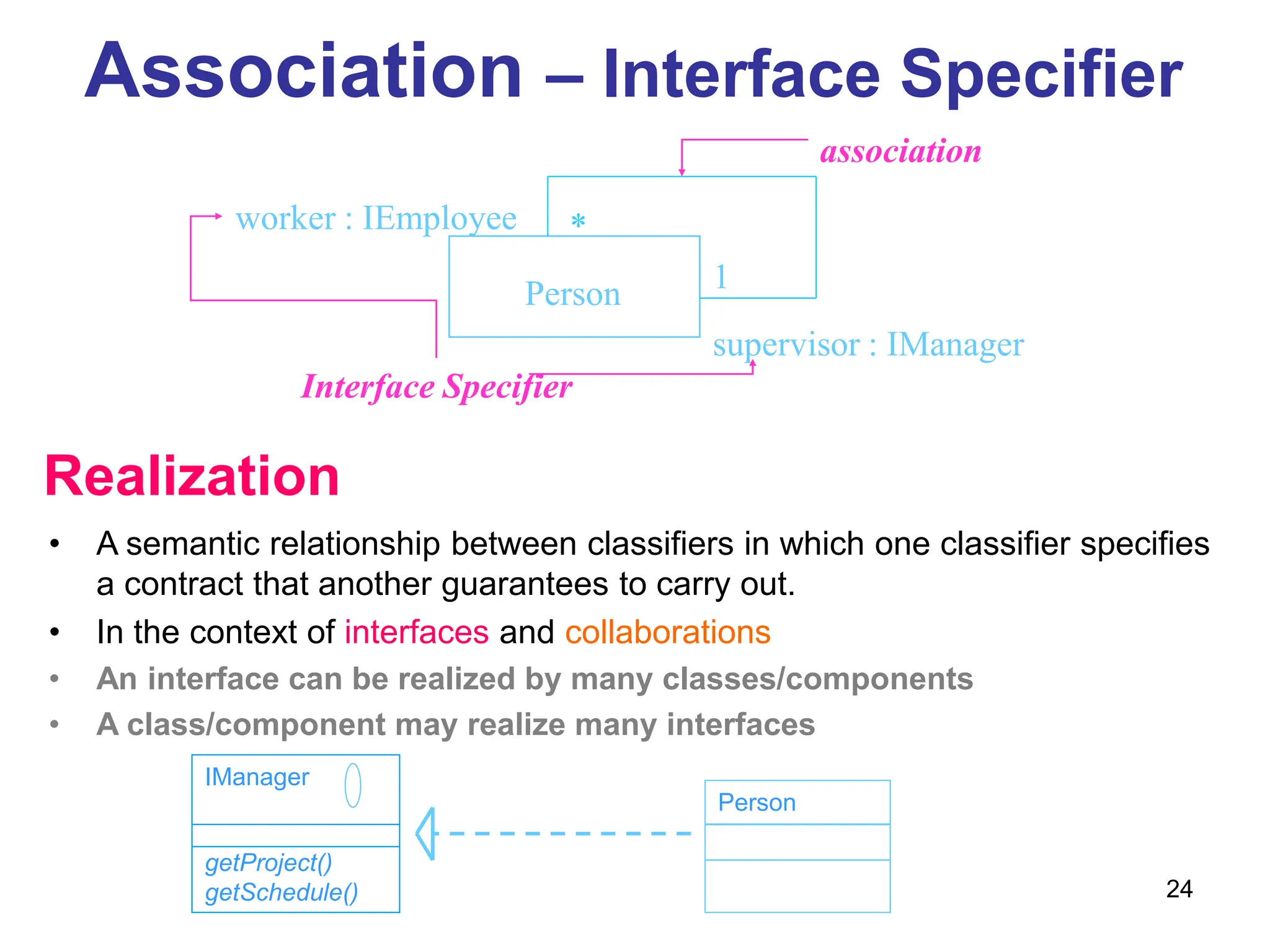
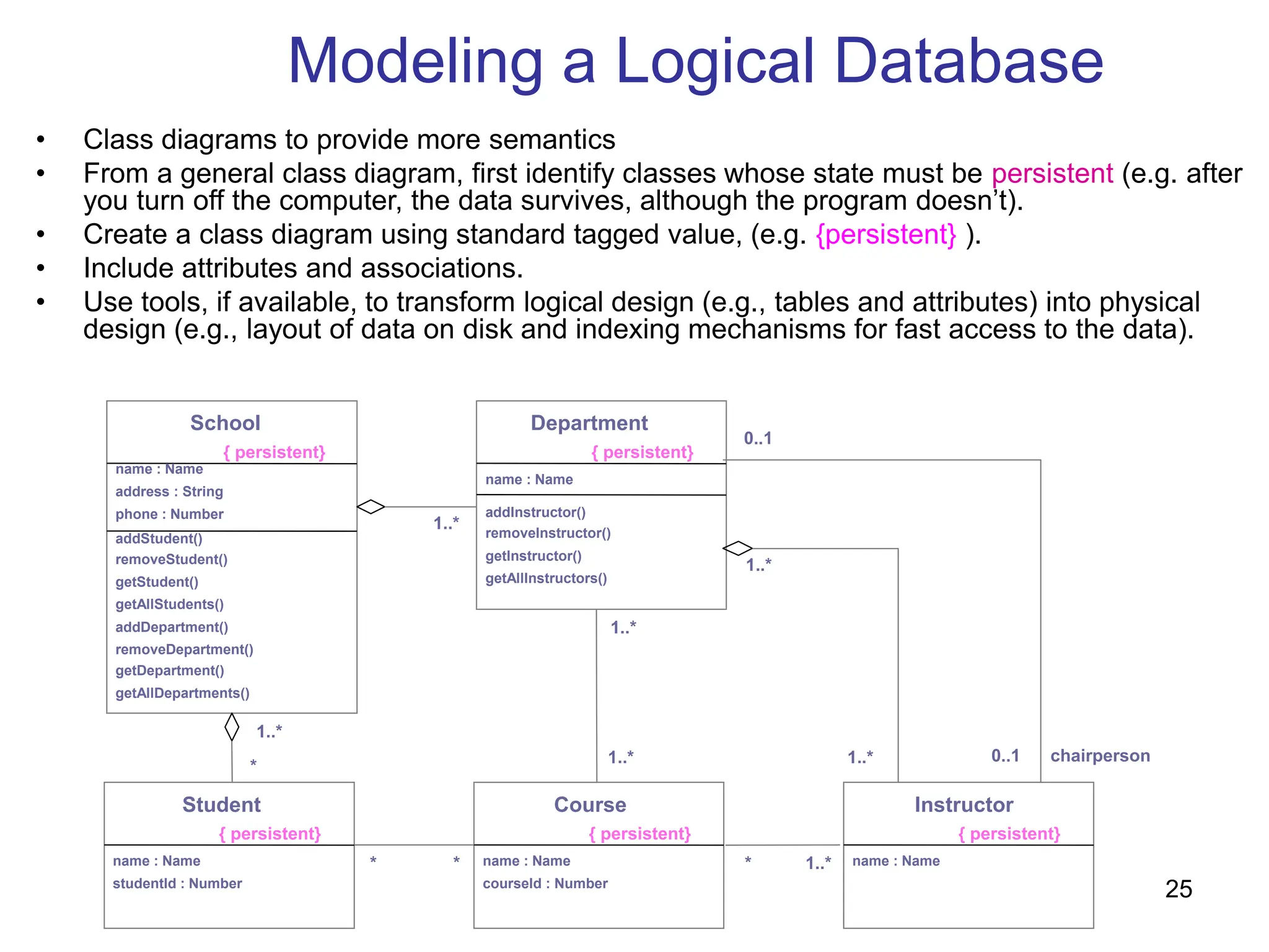
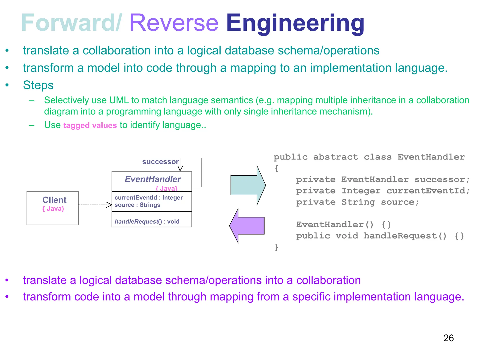
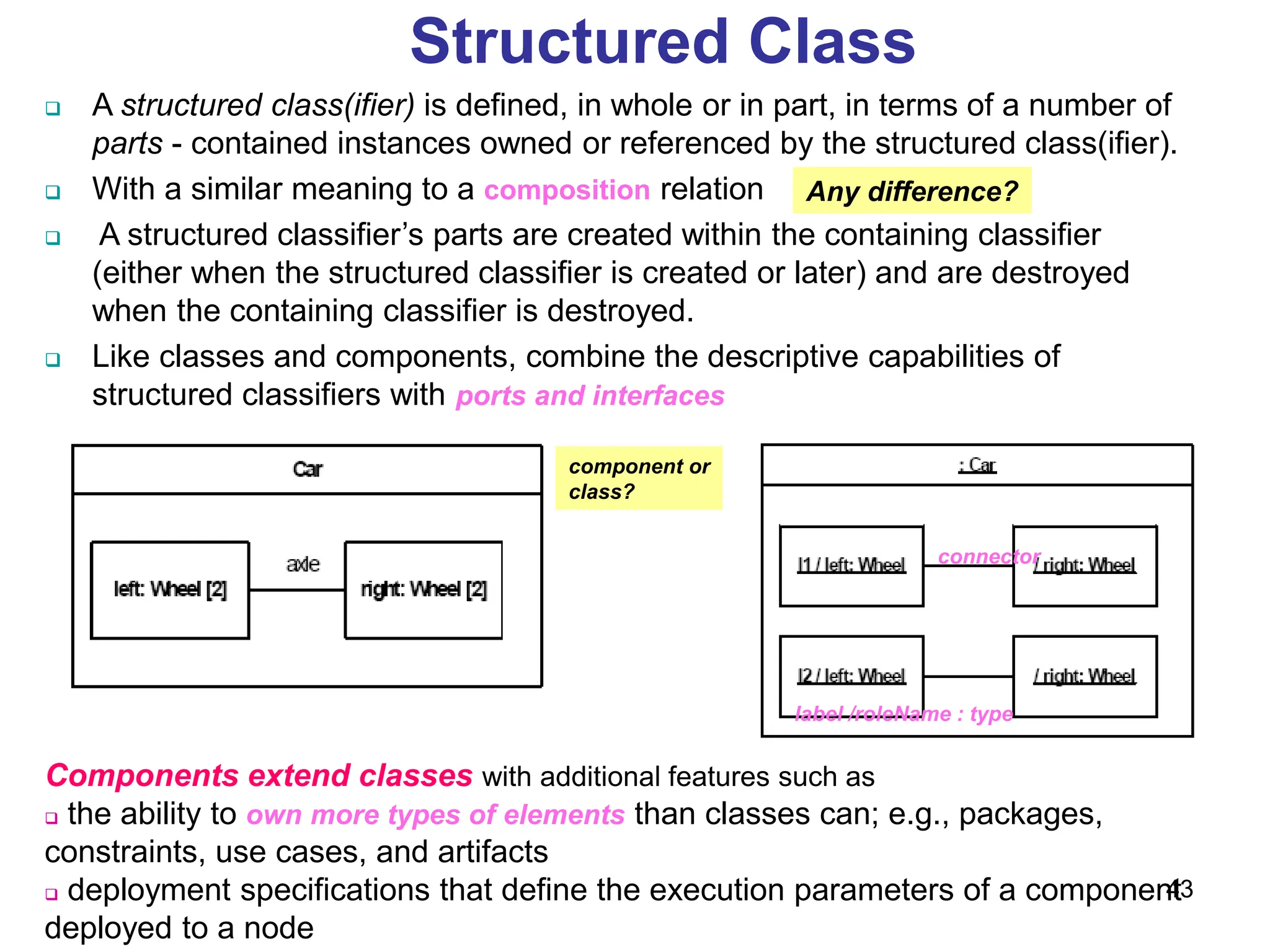
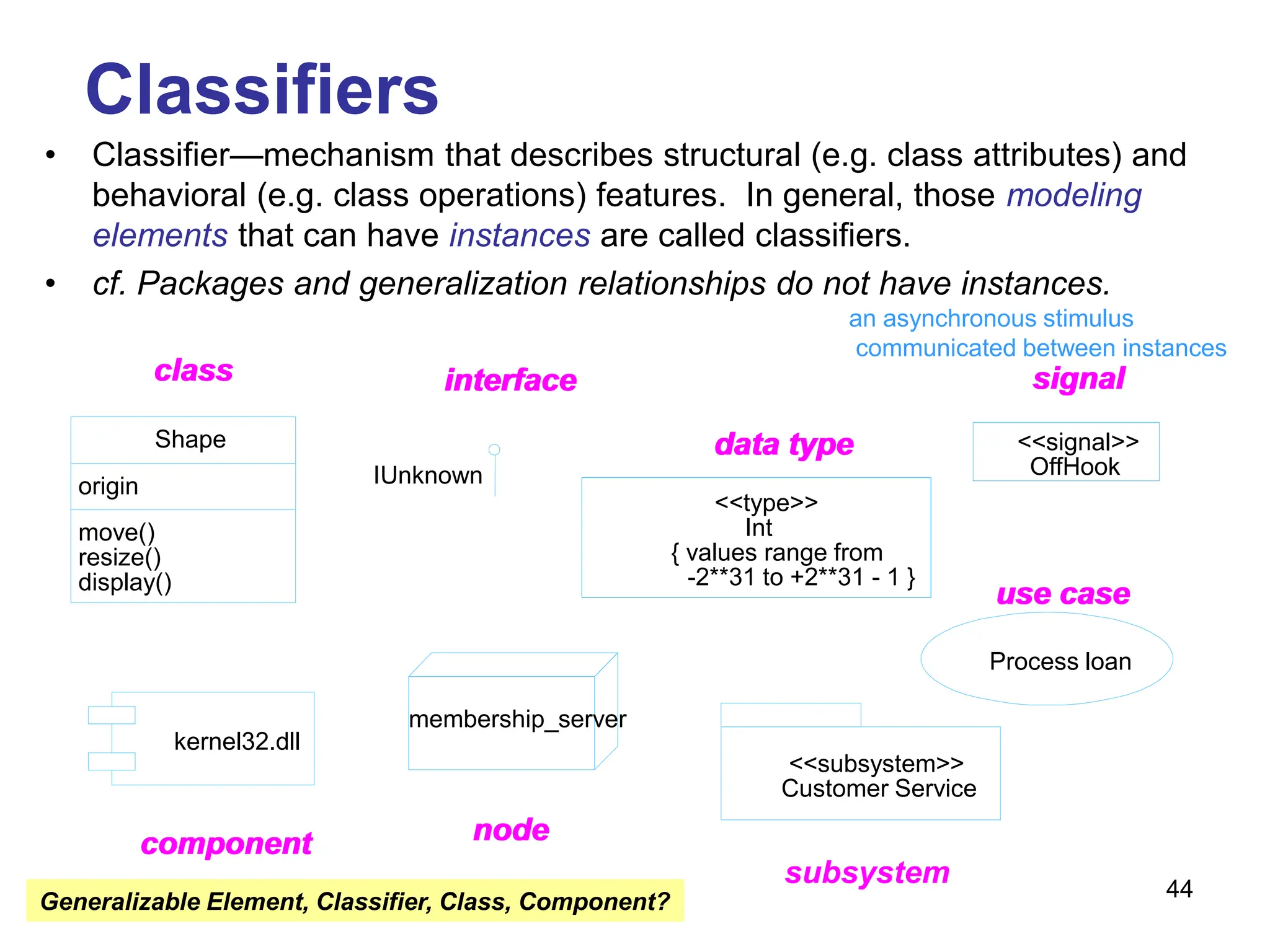
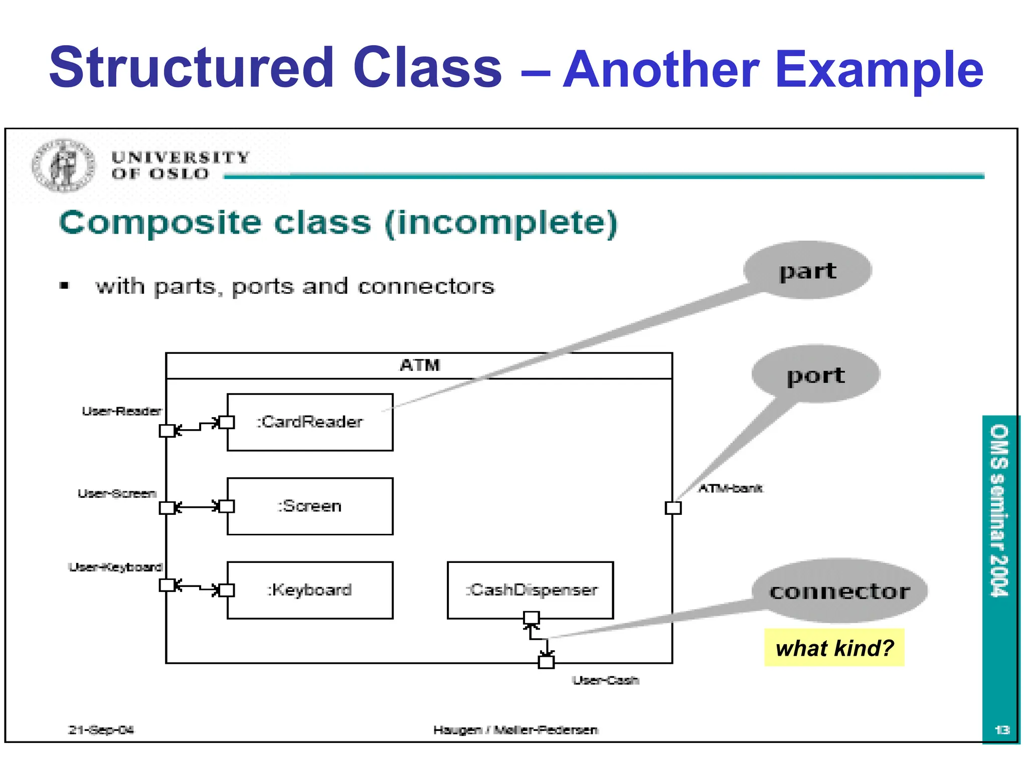
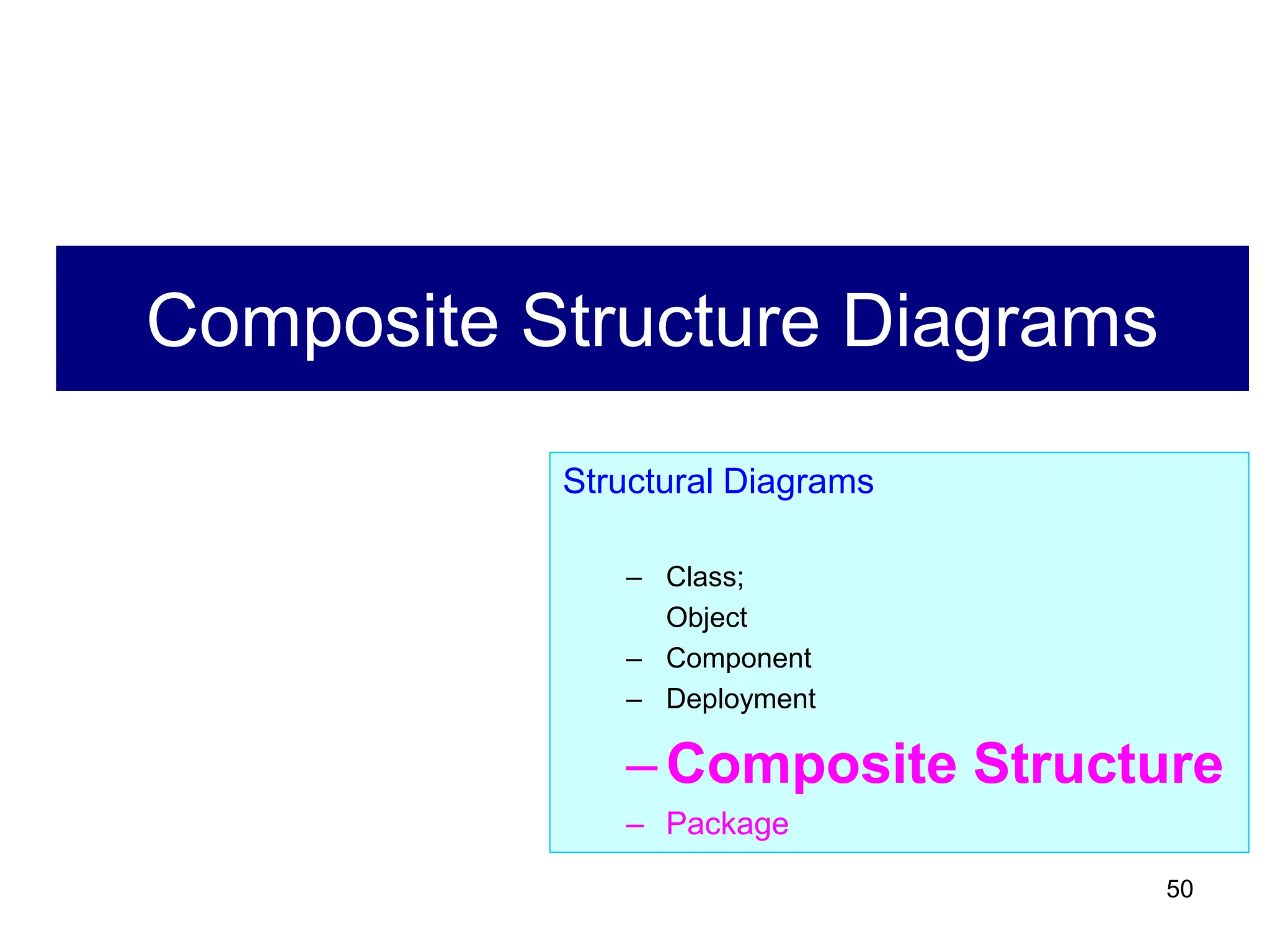
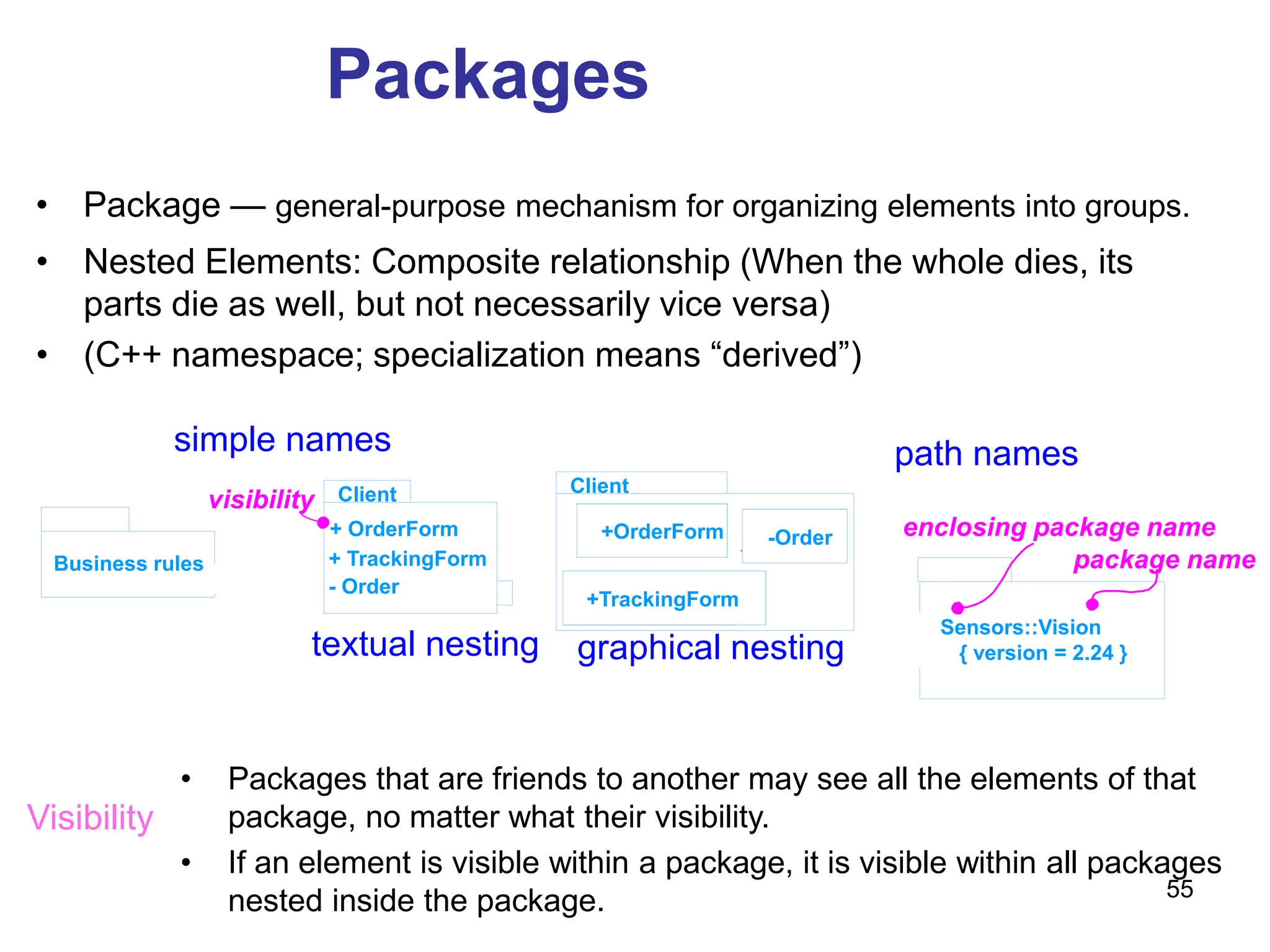
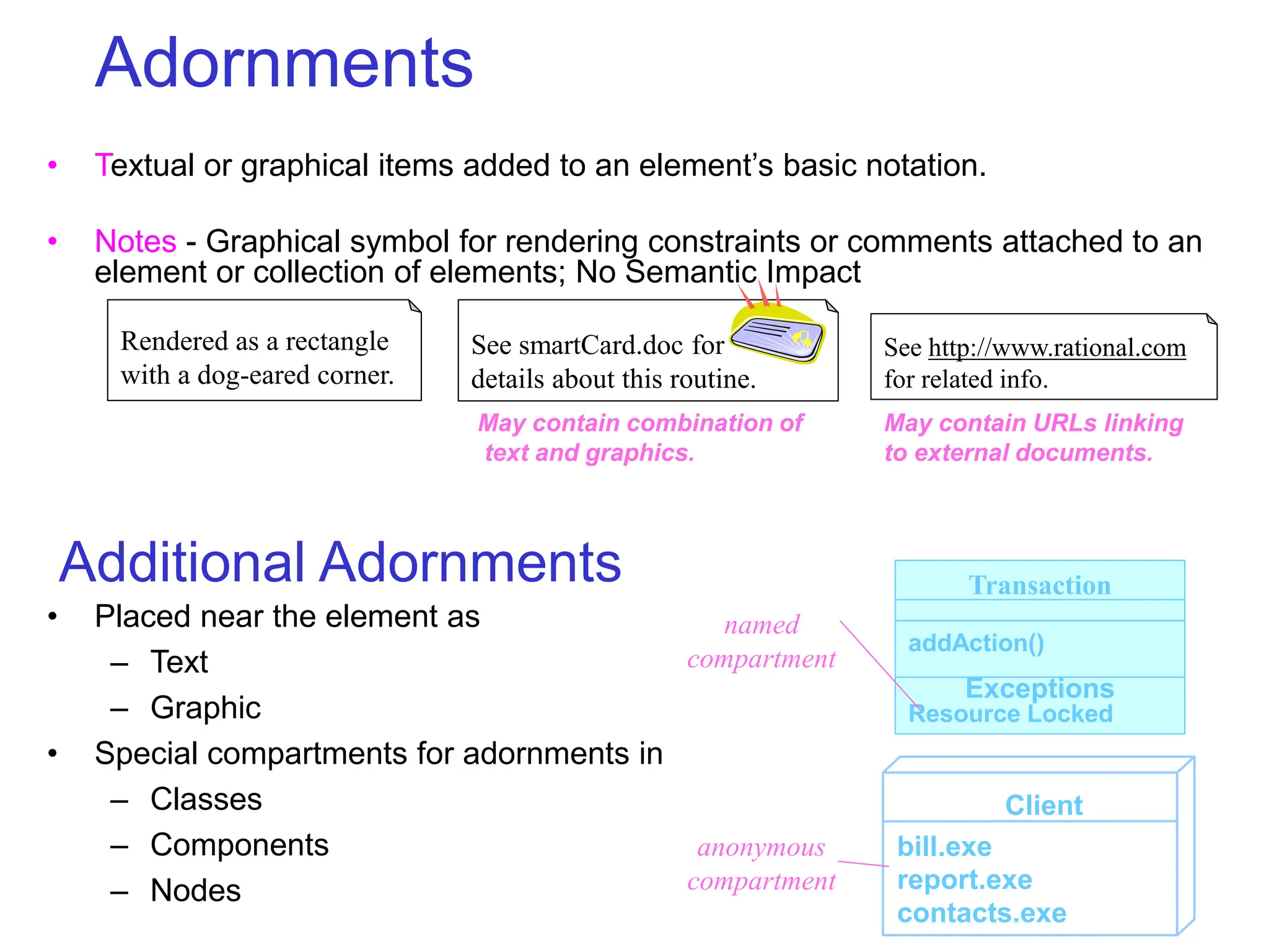
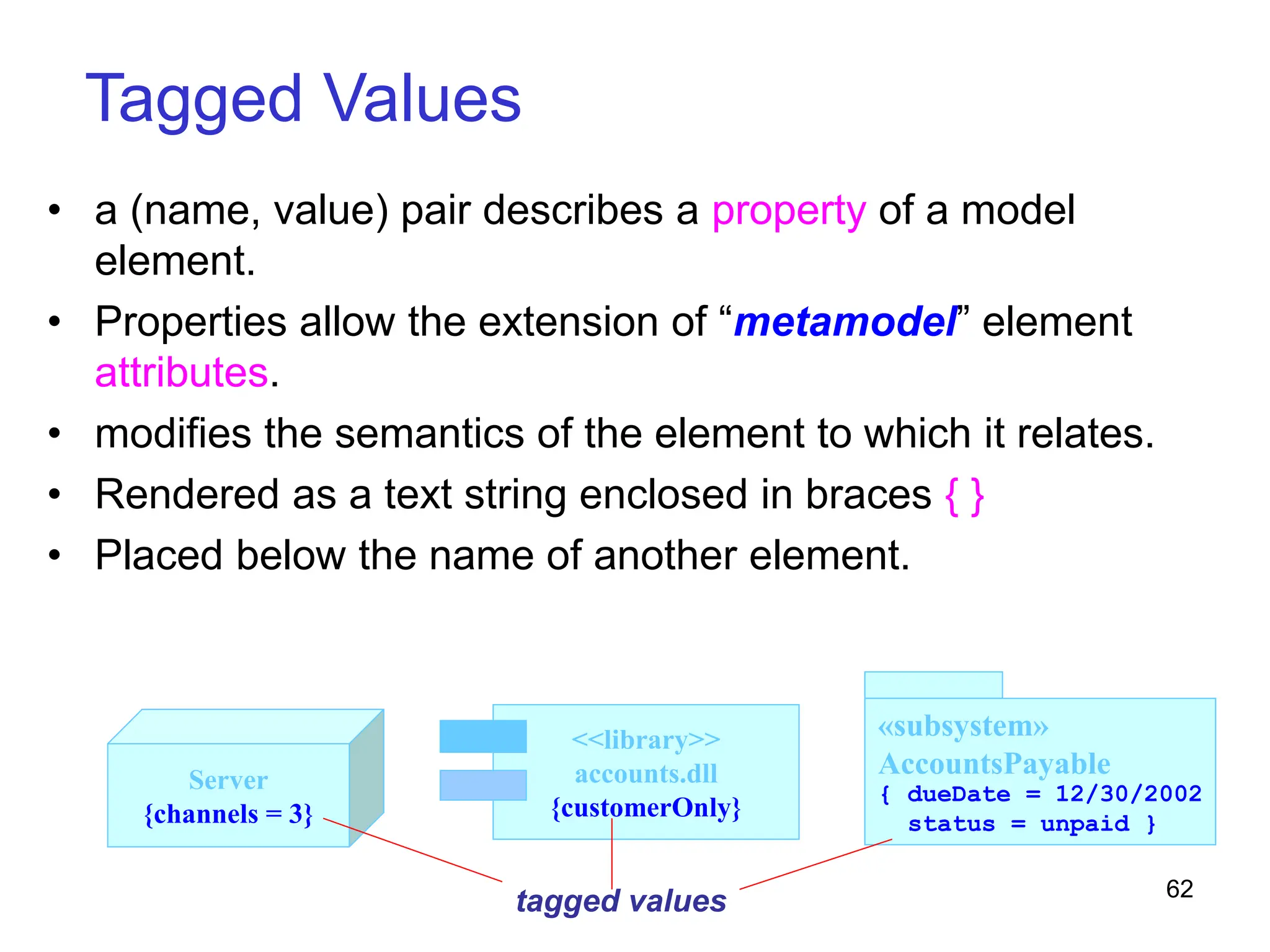
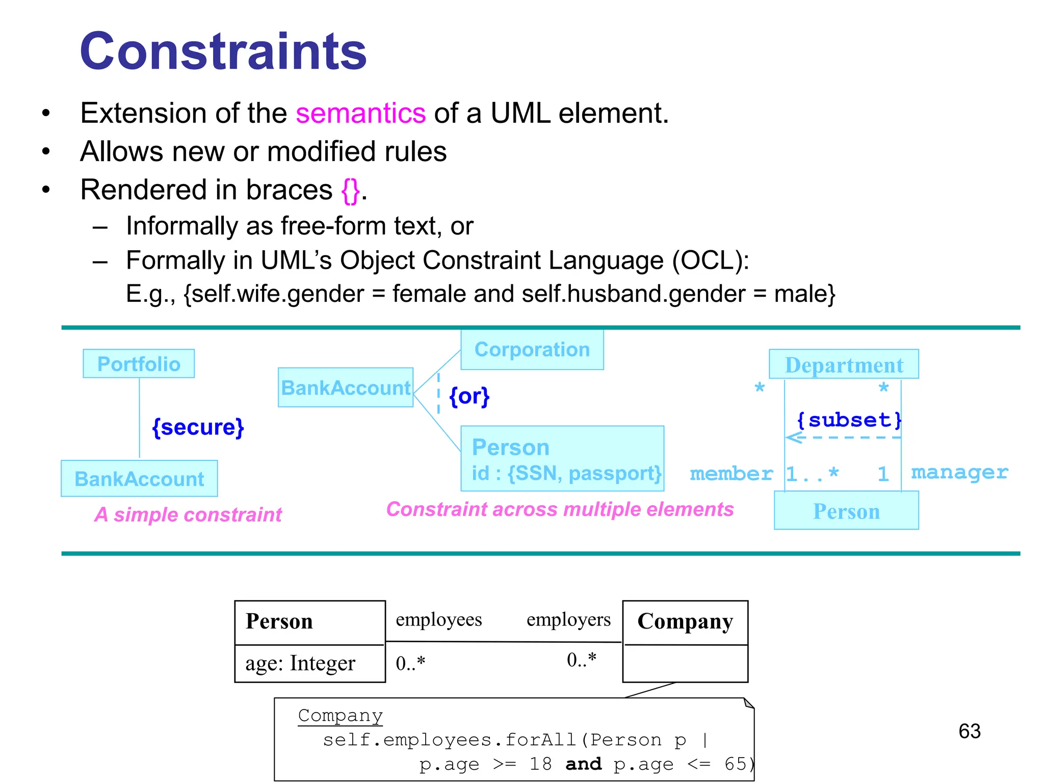
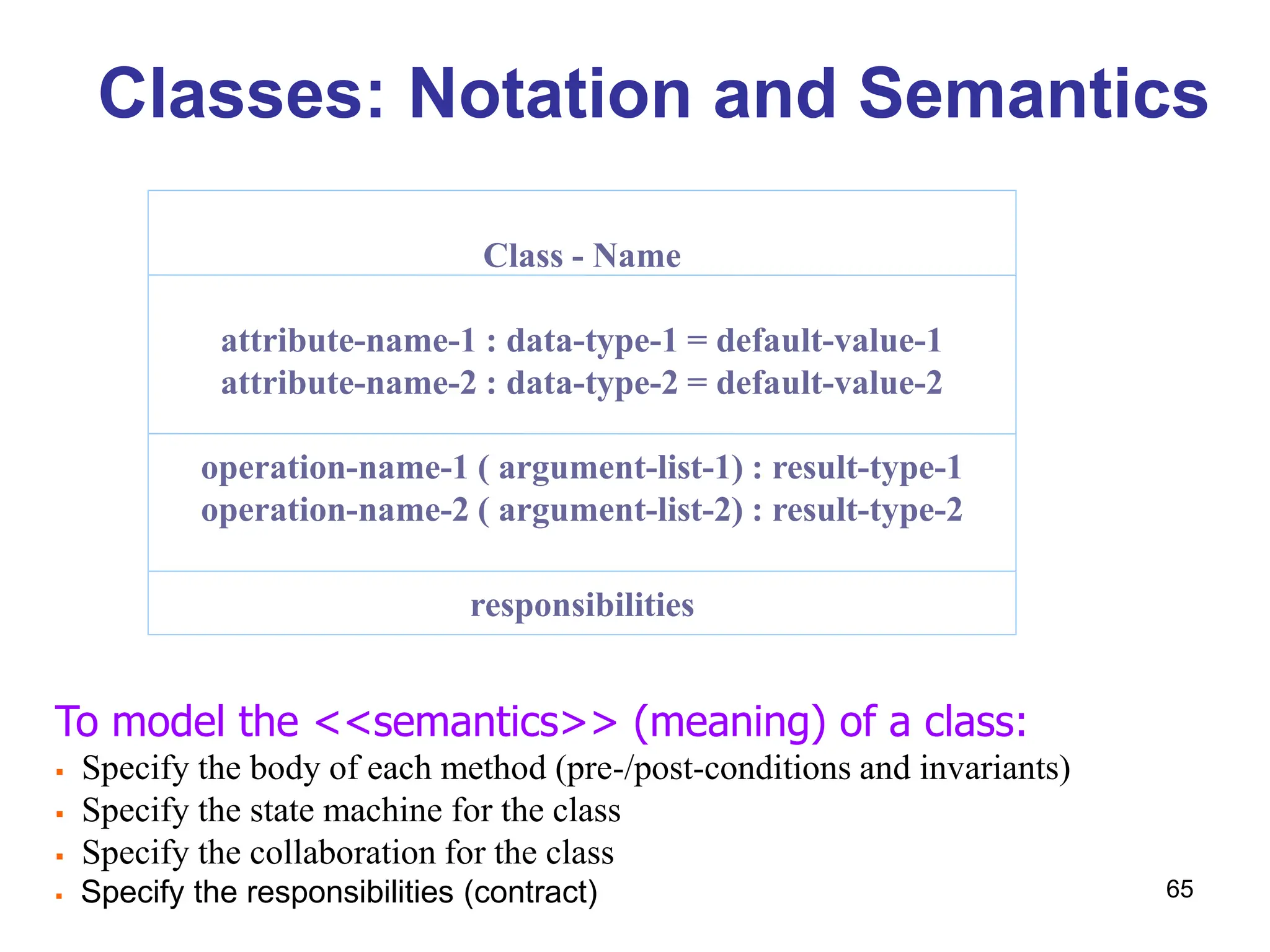
The document discusses advanced features of UML, emphasizing structural diagrams and their roles in representing the static aspects of systems. Key topics include class diagrams, responsibilities, relationships, associations, and component diagrams, detailing their definitions and significance in object-oriented modeling. It also covers the transformation of UML diagrams into logical database schemas and the importance of accurately modeling instances and components for system architecture.
![8
consolePort [ 2..* ] : Port
NetworkController
1
ControlRod
3
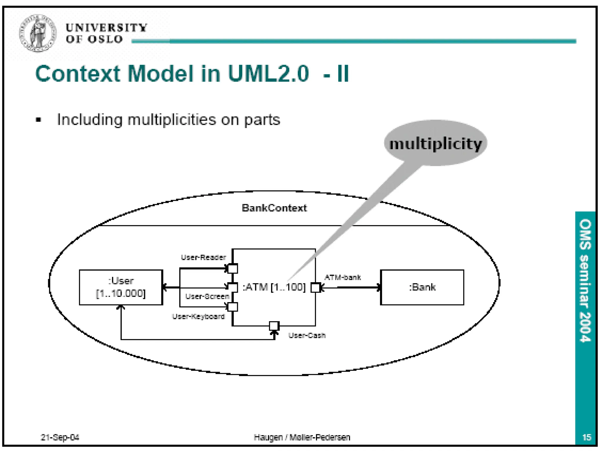
multiplicity
singleton
public class Singleton {
private static Singleton instance = null;
private Singleton() {}
public static Singleton getInstance() {
if (instance == null) {
instance = new Singleton();
}
return instance;
}
}
Multiplicity
Singleton
- instance
+ getInstance():Singleton
consolePort [ 2..* ] : Port
NetworkController
Using Design Pattern](https://image.slidesharecdn.com/m031structuraldiagrams-240417003622-22c43502/75/M03_1_Structur-alDiagrams-ppt-8-2048.jpg)
![29
: keyCode
Instances & Objects - Visual Representation
: Multimedia :: AudioStream
t : Transaction
myCustomer
r : FrameRenderThread
c : Phone
[WaitingForAnswer]
myCustomer
id : SSN = “432-89-1738”
active = True
agent :
named instance
instance with current state
instance with attribute values
active object
(with a thicker border; owns a
thread or process and can
initiate control activity)
multiobject orphan instance
(type unknown)
anonymous instance](https://image.slidesharecdn.com/m031structuraldiagrams-240417003622-22c43502/75/M03_1_Structur-alDiagrams-ppt-29-2048.jpg)
![30
Instances & Objects - Modeling Concrete Instances
• Expose the stereotypes, tagged values, and attributes.
• Show these instances and their relationships in an object diagram.
current: Transaction
primaryAgent
[searching]
: Transaction
LoanOfficer
<<instanceOf>>
current := retrieve()
Instances & Objects - Modeling Prototypical Instances
• Show these instances and their relationships in an interaction diagram or an
activity diagram.
a: CallingAgent c: Connection
1 : create
2: enableConnection
2.1 : startBilling](https://image.slidesharecdn.com/m031structuraldiagrams-240417003622-22c43502/75/M03_1_Structur-alDiagrams-ppt-30-2048.jpg)
![31
Instances & Objects – More Examples
client servers
1: aServer := find(criteria)
d: Directory
1: sort()
list()
contents: File
d: Directory
1: addElement(f)
addFile(f:File)
contents: File
:Server
aServer:Server
2: process(request)
c : Company
s : Department
name = “Sales”
uss : Department
name = “US Sales”
erin : Person
name = “Erin”
employeeID = 4362
title = “VP of Sales”
rd : Department
name = “R&D”
: ContactInfomation
address = “1472 Miller St.”
manager
call ::= label [guard] [“*”] [return-val-list “:=“] msg-name “(“ arg-list “)”
d: Directory
1*: changeMode(readOnly)
secureAll()
f: File *](https://image.slidesharecdn.com/m031structuraldiagrams-240417003622-22c43502/75/M03_1_Structur-alDiagrams-ppt-31-2048.jpg)
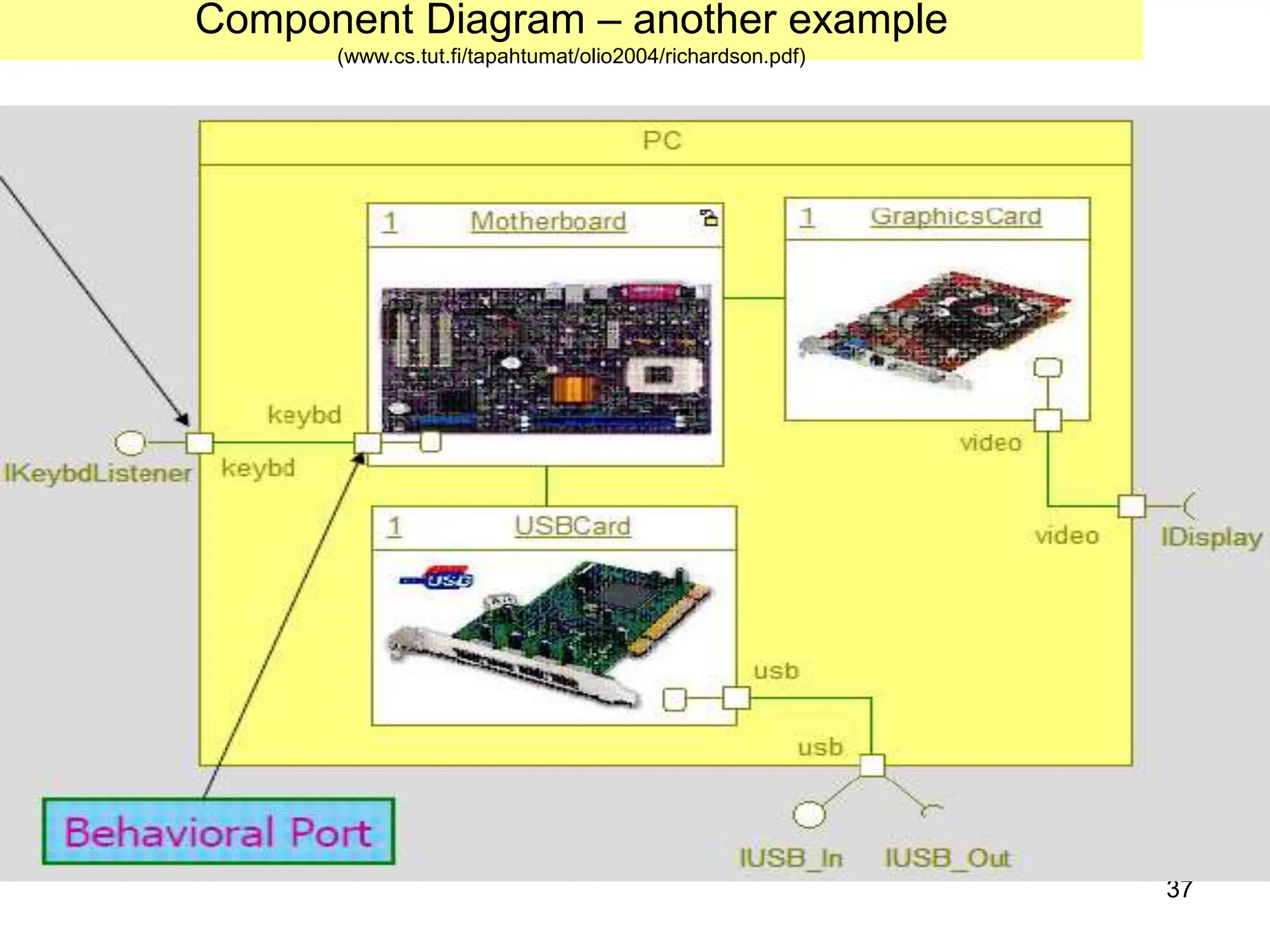
![38
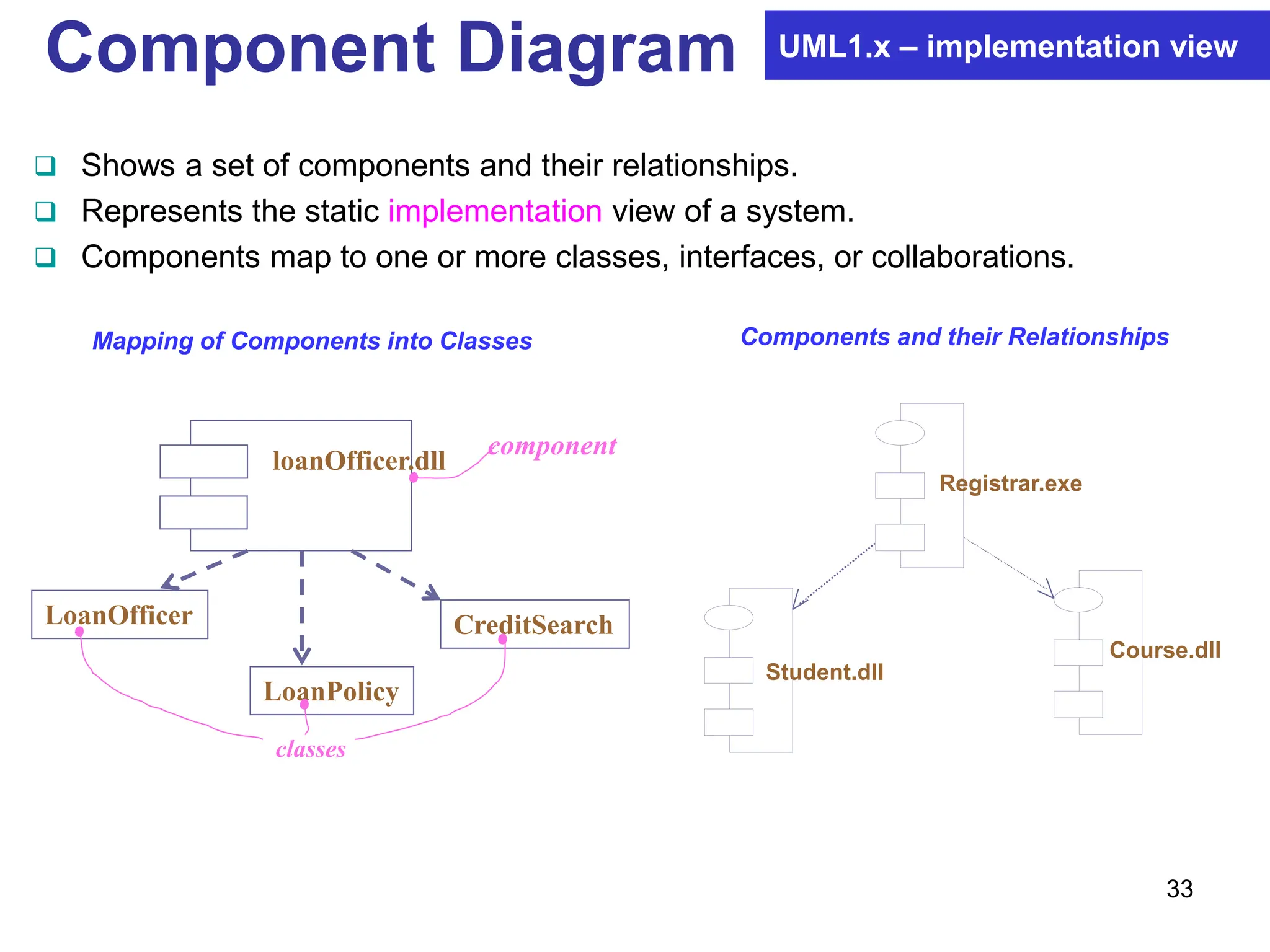
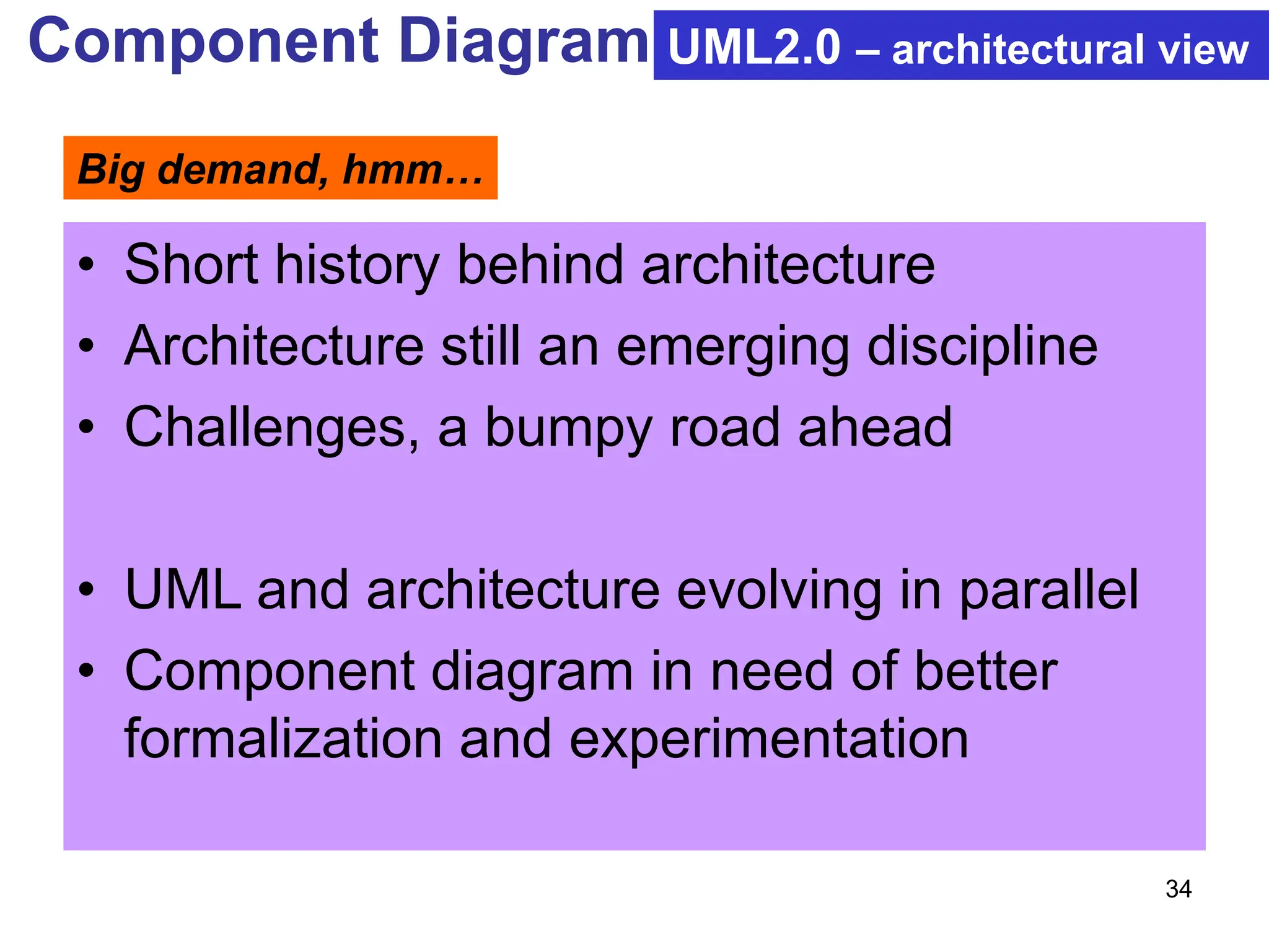
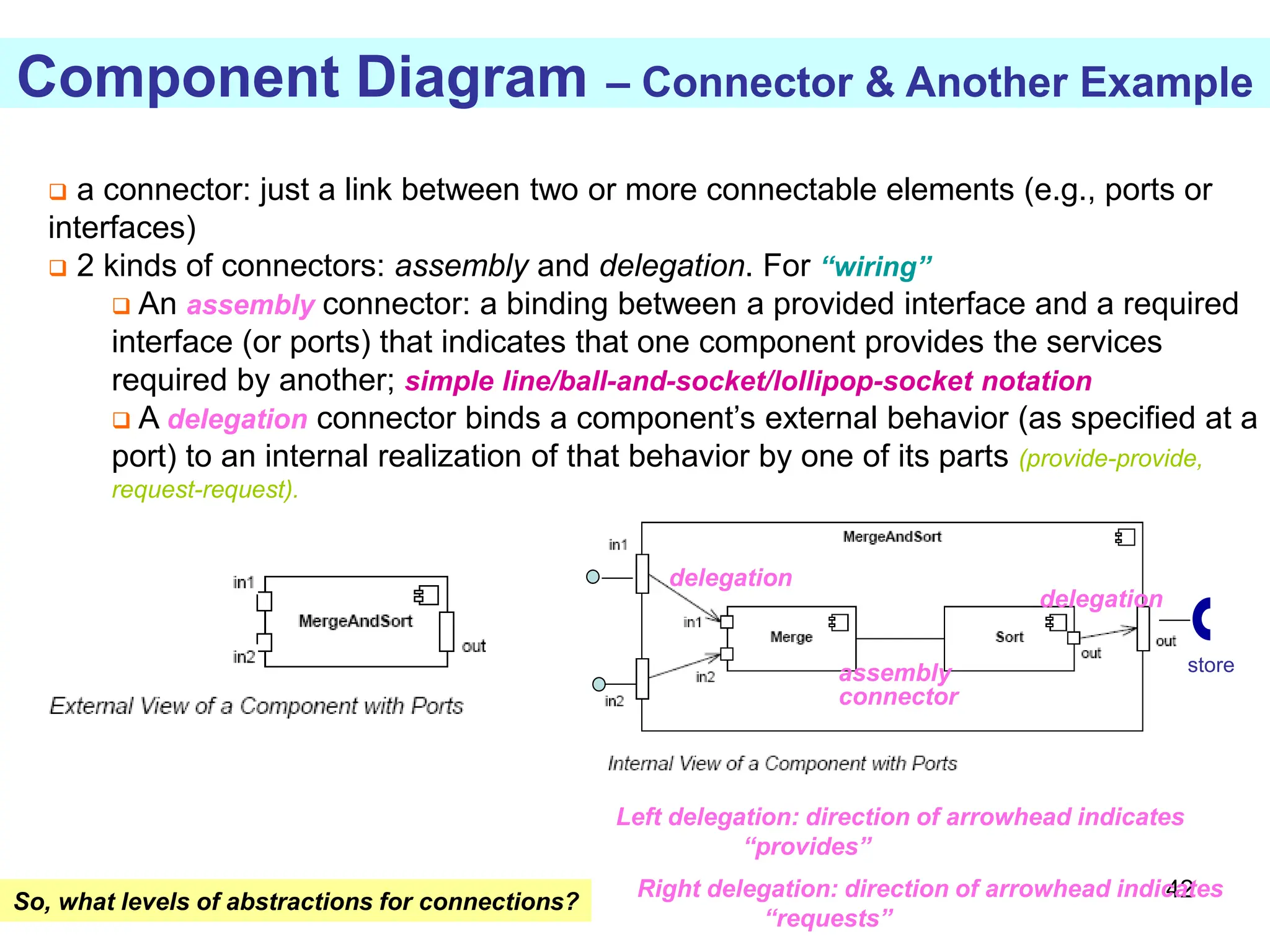
Component Diagram UML2.0 – architectural view
Component
Component
Explicit description of interfaces:
provided services to other components
requested services from other components
An interface is a collection of 1..* methods, and 0..* attributes
Interfaces can consist of synchronous and / or asynchronous operations
A port (square) is an interaction point between the component and its environment.
Can be named; Can support uni-directional (either provide or require) or bi-directional
(both provide and require) communication; Can support multiple interfaces.
possibly concurrent interactions
fully isolate an object’s internals from its environment
lollipop
socket
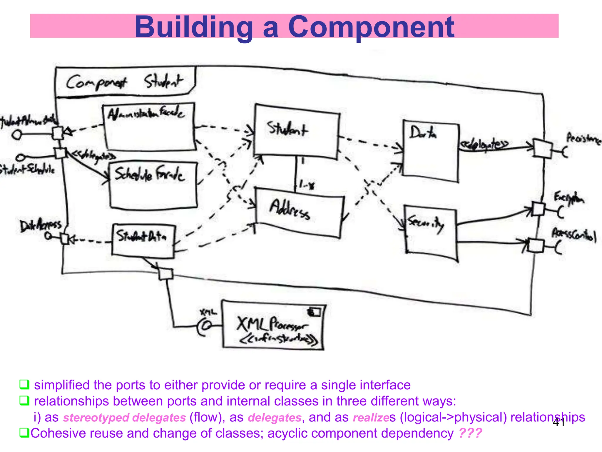
Student
StudentAdministration
StudentSchedule
AccessControl
Encription
Persistence
DataAccess
security
Data[1..*]
Incoming
signals/calls
Outgoing
signals/calls
caller or callee?](https://image.slidesharecdn.com/m031structuraldiagrams-240417003622-22c43502/75/M03_1_Structur-alDiagrams-ppt-38-2048.jpg)
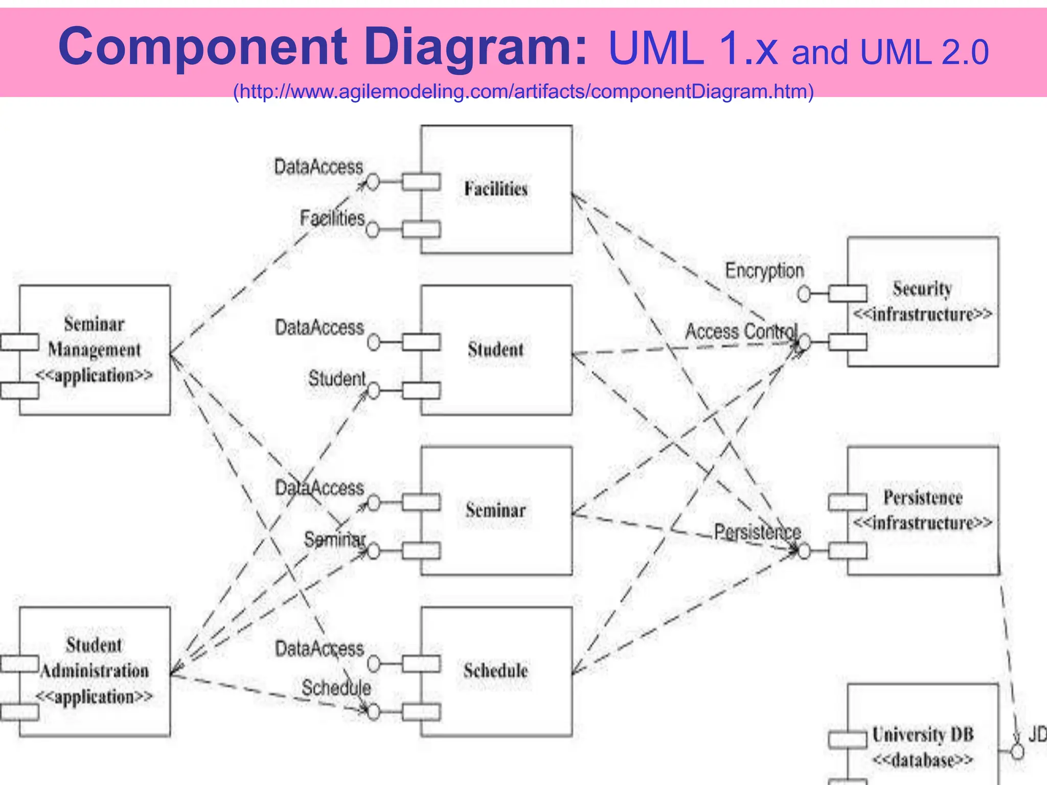
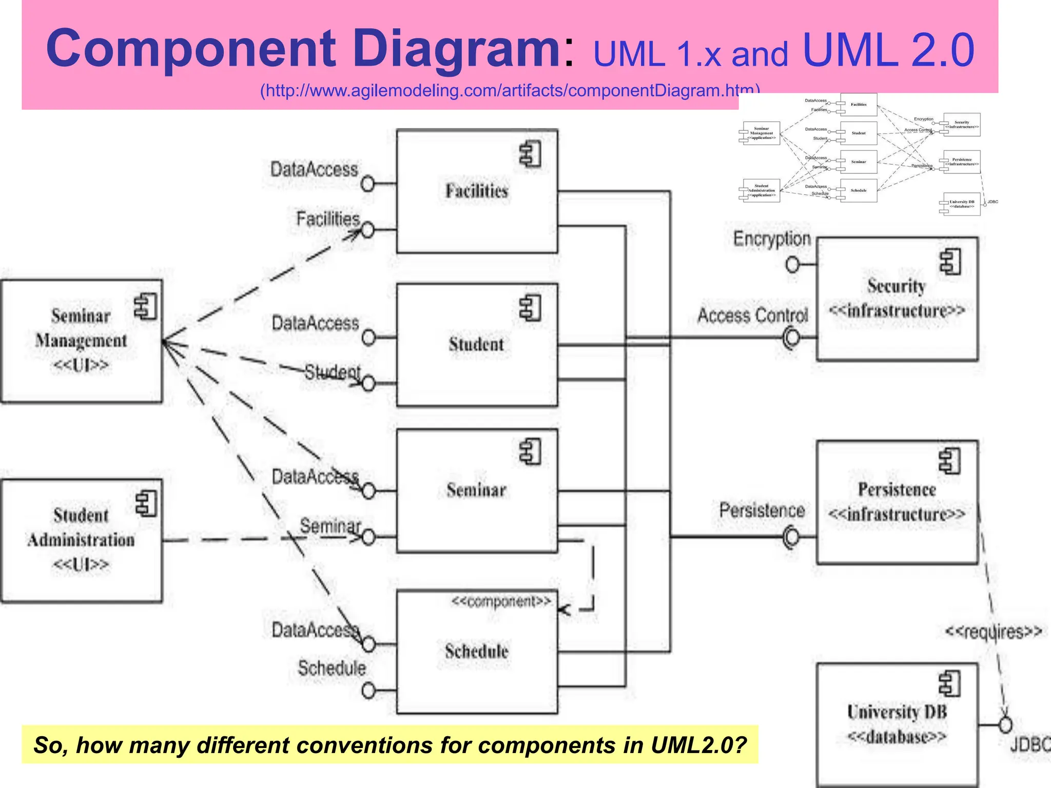
![52
Variations [Rumbaugh – UML 2.0 Reference: p234]
Sale
buyer: Agent
item: Property
seller: Agent
role name
role type
role
collaboration name
Collaboration definition
ShiloPurchase: Sale
Shilo: Land
item
Edward: Architect Bala: Analyst
buyer seller
role name
Collaboration use in object diagram
collaborating object
collaboration name
use name](https://image.slidesharecdn.com/m031structuraldiagrams-240417003622-22c43502/75/M03_1_Structur-alDiagrams-ppt-52-2048.jpg)
![58
Class Package Diagrams
(http://www.agilemodeling.com/artifacts/packageDiagram.htm)
• Classes related through inheritance, composition or communication
often belong in the same package
Seminar
Registration
<<application>>
Schedule
Student
Professor
Java
Infrastructure
<<technical>>
<<import>>
Contact
Point
<<import>>
<<import>>
<<import>>
<<import>>
• A frame depicts the contents of a package (or components, classes, operations, etc.)
• Heading: rectangle with a cut-off bottom-right corner, [kind] name [parameter]
Seminar Course
Enrollment
Location
Time
1
0..*
1..* 1
1..*
1
held at
Package Schedule
A frame encapsulates
a collection of collaborating instances or
refers to another representation of such](https://image.slidesharecdn.com/m031structuraldiagrams-240417003622-22c43502/75/M03_1_Structur-alDiagrams-ppt-58-2048.jpg)
![61
Stereotypes
• Allow controlled extension of metamodel classes.
[UML11_Metamodel_Diagrams.pdf]
• Graphically rendered as
– Name enclosed in guillemets (<< >> )
• <<stereotype>>
– New icon
«metaclass»
ModelElement
Internet
• The new building block can have
• its own special properties through a set of tagged values
• its own semantics through constraints
• Mechanisms for extending the UML vocabulary.
• Allows for new modeling building blocks or parts.](https://image.slidesharecdn.com/m031structuraldiagrams-240417003622-22c43502/75/M03_1_Structur-alDiagrams-ppt-61-2048.jpg)
![66
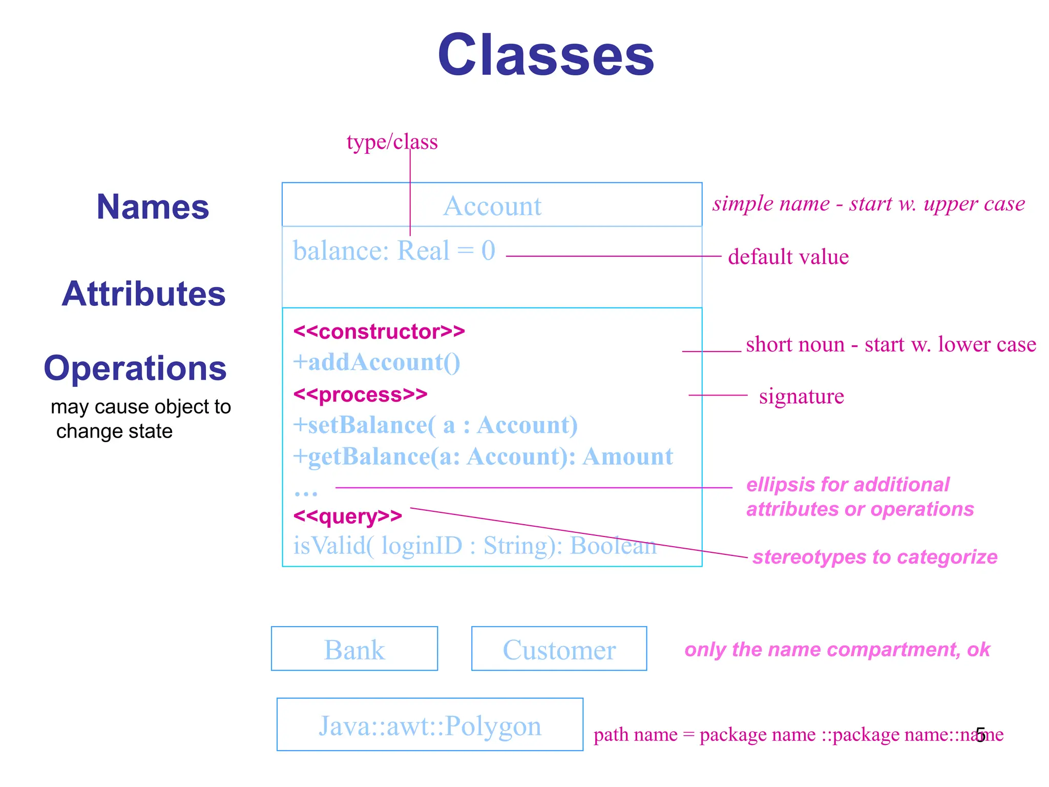
Attributes
• Syntax
[ visibility ] name [ multiplicity ] [ : type ] [ = initial-value ] [ {property-string } ]
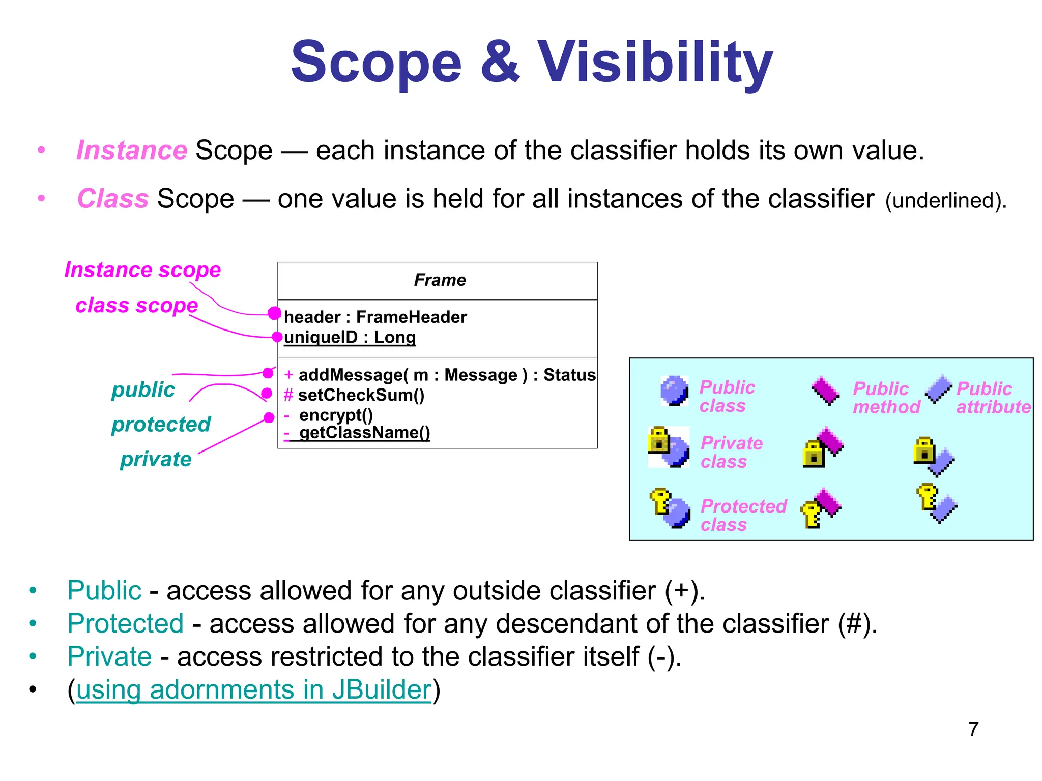
• Visibility
+ public; - private; # protected; {default = +}
• type
– There are several defined in Rational Rose.
– You can define your own.
• property-string
Built-in property-strings:
– changeable—no restrictions (default)
– addOnly—values may not be removed or altered, but may be added
– frozen—may not be changed after initialization
Or you can define your own: e.g. {leaf}
origin Name only
+ origin Visibility and name
origin : Point Name and type
head : *Item Name and complex type
name [ 0..1 ] : String Name, multiplicity, and type
origin : Point = { 0, 0 } Name, type, and initial value
id : Integer { frozen } Name and property](https://image.slidesharecdn.com/m031structuraldiagrams-240417003622-22c43502/75/M03_1_Structur-alDiagrams-ppt-66-2048.jpg)
![67
Operations
• Syntax
[ visibility ] name [ (parameter-list ) ] [ : return-type ] [ (property-string) ]
• Visibility
+ public; - private; # protected; {default = +}
• parameter-list syntax
[ direction ] name : type [ = default-value ]
• direction
– in—input parameter; may not be modified
– out—output parameter; may be modified
– inout—input parameter; may be modified
• property-string
– leaf
– isQuery—state is not affected
– sequential—not thread safe
– guarded—thread safe (Java synchronized)
– concurrent—typically atomic; safe for multiple flows of control](https://image.slidesharecdn.com/m031structuraldiagrams-240417003622-22c43502/75/M03_1_Structur-alDiagrams-ppt-67-2048.jpg)


![[DSC Europe 25] Dusan Jovicic - AI Story: From on-prem to cloud and back agai...](https://cdn.slidesharecdn.com/ss_thumbnails/8kp49m6uq22ifnbwhfnk-2-251205085715-964d11a6-thumbnail.jpg?width=640&height=640&fit=bounds)


![[DSC Europe 25] Petar Zivanov - AI meets documents From chatbots to AI-powere...](https://cdn.slidesharecdn.com/ss_thumbnails/xer2bb6nrdc8pdpev0pc-8-251204082258-7c2fa4a1-thumbnail.jpg?width=640&height=640&fit=bounds)


![[DSC Europe 25] Nikola Rajovic - Hardware Technologies Under the Hood: RISC-V...](https://cdn.slidesharecdn.com/ss_thumbnails/o2gptrmtoyqndgoshwgq-dsc2025-tenstorrent-rajovic-251205090438-814685f5-thumbnail.jpg?width=640&height=640&fit=bounds)

![[DSC Europe 25] Bogdan Daniel Maruneac - AI - It starts with you.pptx](https://cdn.slidesharecdn.com/ss_thumbnails/odov3snhrcqs9hx5ny2n-4-251205085715-f1daacfe-thumbnail.jpg?width=640&height=640&fit=bounds)

![[DSC Europe 25] Max Talanov - Non digital NNs.pptx](https://cdn.slidesharecdn.com/ss_thumbnails/wif8tr3gtua74qvtopke-non-digital-nns-251205090438-26b0eea6-thumbnail.jpg?width=640&height=640&fit=bounds)
