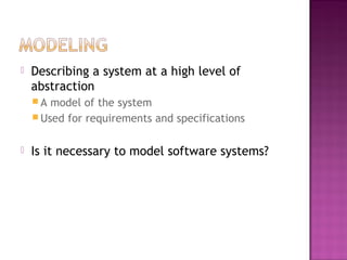
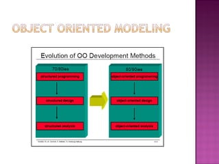
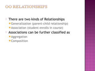
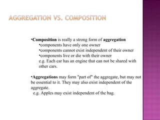
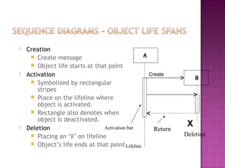
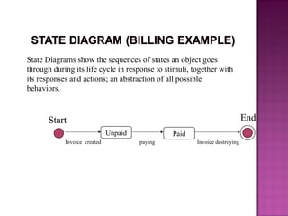
support@myassignmenthelpers.com
http://www.myassignmenthelpers.com/
 Describing a system at a high level of
abstraction
 A model of the system
 Used for requirements and specifications
 Is it necessary to model software systems?
 UML stands for “Unified Modeling Language”
 It is a industry-standard graphical language for
specifying, visualizing, constructing, and
documenting the artifacts of software systems
 The UML uses mostly graphical notations to
express the OO analysis and design of software
projects.
 Simplifies the complex process of software
design
 Use graphical notation to communicate more
clearly than natural language (imprecise) and
code(too detailed).
 Help acquire an overall view of a system.
 UML is not dependent on any one language or
technology.
 UML moves us from fragmentation to
standardization.
 Use Case Diagram
 Class Diagram
 Sequence Diagram
 Collaboration Diagram
 State Diagram
This is only a subset of diagrams … but are most
widely used
 Used for describing a set of user scenarios
 Mainly used for capturing user requirements
 Work like a contract between end user and
software developers
(TogetherSoft, Inc)
 Used for describing structure and behavior in
the use cases
 Provide a conceptual model of the system in
terms of entities and their relationships
 Used for requirement capture, end-user
interaction
 Detailed class diagrams are used for
developers
 Each class is represented by a rectangle subdivided into
three compartments
 Name
 Attributes
 Operations
 Modifiers are used to indicate visibility of attributes and
operations.
 ‘+’ is used to denote Public visibility (everyone)
 ‘#’ is used to denote Protected visibility (friends and
derived)
 ‘-’ is used to denote Private visibility (no one)
 By default, attributes are hidden and operations are
visible.
Account_Name
- Customer_Name
- Balance
+addFunds( )
+withDraw( )
+transfer( )
Name
Attributes
Operations
 There are two kinds of Relationships
 Generalization (parent-child relationship)
 Association (student enrolls in course)
 Associations can be further classified as
 Aggregation
 Composition
 Represent relationship between instances of classes
Student enrolls in a course
Courses have students
Courses have exams
Etc.
 Association has two ends
Role names (e.g. enrolls)
Multiplicity (e.g. One course can have many students)
Navigability (unidirectional, bidirectional)
•CompositionComposition is really a strong form of aggregation
•components have only one owner
•components cannot exist independent of their owner
•components live or die with their owner
e.g. Each car has an engine that can not be shared with
other cars.
•Aggregations may form "part of" the aggregate, but may not
be essential to it. They may also exist independent of the
aggregate.
e.g. Apples may exist independent of the bag.
 Creation
 Create message
 Object life starts at that point
 Activation
 Symbolized by rectangular
stripes
 Place on the lifeline where
object is activated.
 Rectangle also denotes when
object is deactivated.
 Deletion
 Placing an ‘X’ on lifeline
 Object’s life ends at that point
Activation bar
A
B
Create
X
Deletion
Return
Lifeline
State Diagrams show the sequences of states an object goes
through during its life cycle in response to stimuli, together with
its responses and actions; an abstraction of all possible
behaviors.
Unpaid
Start End
Paid
Invoice created paying Invoice destroying

UML Diagram Assignment Help, UML Diagram Homework Help

  • 1.
  • 2.
     Describing asystem at a high level of abstraction  A model of the system  Used for requirements and specifications  Is it necessary to model software systems?
  • 4.
     UML standsfor “Unified Modeling Language”  It is a industry-standard graphical language for specifying, visualizing, constructing, and documenting the artifacts of software systems  The UML uses mostly graphical notations to express the OO analysis and design of software projects.  Simplifies the complex process of software design
  • 5.
     Use graphicalnotation to communicate more clearly than natural language (imprecise) and code(too detailed).  Help acquire an overall view of a system.  UML is not dependent on any one language or technology.  UML moves us from fragmentation to standardization.
  • 7.
     Use CaseDiagram  Class Diagram  Sequence Diagram  Collaboration Diagram  State Diagram This is only a subset of diagrams … but are most widely used
  • 8.
     Used fordescribing a set of user scenarios  Mainly used for capturing user requirements  Work like a contract between end user and software developers
  • 9.
  • 10.
     Used fordescribing structure and behavior in the use cases  Provide a conceptual model of the system in terms of entities and their relationships  Used for requirement capture, end-user interaction  Detailed class diagrams are used for developers
  • 11.
     Each classis represented by a rectangle subdivided into three compartments  Name  Attributes  Operations  Modifiers are used to indicate visibility of attributes and operations.  ‘+’ is used to denote Public visibility (everyone)  ‘#’ is used to denote Protected visibility (friends and derived)  ‘-’ is used to denote Private visibility (no one)  By default, attributes are hidden and operations are visible.
  • 12.
    Account_Name - Customer_Name - Balance +addFunds() +withDraw( ) +transfer( ) Name Attributes Operations
  • 13.
     There aretwo kinds of Relationships  Generalization (parent-child relationship)  Association (student enrolls in course)  Associations can be further classified as  Aggregation  Composition
  • 14.
     Represent relationshipbetween instances of classes Student enrolls in a course Courses have students Courses have exams Etc.  Association has two ends Role names (e.g. enrolls) Multiplicity (e.g. One course can have many students) Navigability (unidirectional, bidirectional)
  • 15.
    •CompositionComposition is reallya strong form of aggregation •components have only one owner •components cannot exist independent of their owner •components live or die with their owner e.g. Each car has an engine that can not be shared with other cars. •Aggregations may form "part of" the aggregate, but may not be essential to it. They may also exist independent of the aggregate. e.g. Apples may exist independent of the bag.
  • 16.
     Creation  Createmessage  Object life starts at that point  Activation  Symbolized by rectangular stripes  Place on the lifeline where object is activated.  Rectangle also denotes when object is deactivated.  Deletion  Placing an ‘X’ on lifeline  Object’s life ends at that point Activation bar A B Create X Deletion Return Lifeline
  • 17.
    State Diagrams showthe sequences of states an object goes through during its life cycle in response to stimuli, together with its responses and actions; an abstraction of all possible behaviors. Unpaid Start End Paid Invoice created paying Invoice destroying

Editor's Notes

  • #2 Introduce myself
  • #3 1. Describing the system at abstract level to comprehend its complexity 2. Necessary to manage complexity Good for quick understanding of the systems Less chances of conflicting views b/w end-user and system designers
  • #4 Evolution of analysis and design techniques Transition from structured programming to object oriented programming
  • #5 . What does UML stand for? . Industry standard . Graphical notation . Modeling tool … simplifies software design process
  • #6 . More precise than natural language … less detailed than source code . Not dependent on any language . Standardized by various groups
  • #7 History: - Rumbaugh – OMT – object modeling technique Jacobson – OOSE UML … unified approach since 1995 UML 1.5 current … UML 2.0 by the end of 2004