
![What’s in store… Real world problems software solution Functionality – Requirements/Use-cases Object Oriented [OO] Concepts Unified Modeling Language [UML] Simple Design Pattern](https://image.slidesharecdn.com/ooadaltair-090810020209-phpapp01/85/Object-Oriented-Analysis-and-Design-2-320.jpg)
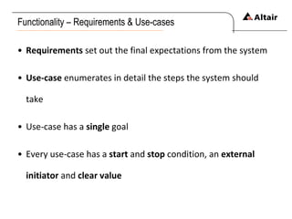
![OO Concepts – I N H E R I T A N C E Build classes based on other classes Avoid duplicating and repeating Inherit behaviour and change [ override ] if required Sub-class should be substitutable for parent class](https://image.slidesharecdn.com/ooadaltair-090810020209-phpapp01/85/Object-Oriented-Analysis-and-Design-7-320.jpg)
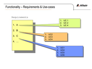
![U M L – Use-Case Diagram Illustrates a unit of functionality Helps visualize functional requirements of a system Include relationships of actors [users] to processes](https://image.slidesharecdn.com/ooadaltair-090810020209-phpapp01/85/Object-Oriented-Analysis-and-Design-12-320.jpg)
![References UML Basic: An Introduction [IBM] Head First - Object Oriented Analysis and Design Wikipedia](https://image.slidesharecdn.com/ooadaltair-090810020209-phpapp01/85/Object-Oriented-Analysis-and-Design-17-320.jpg)

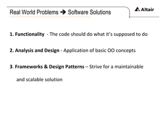
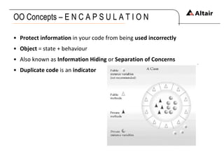
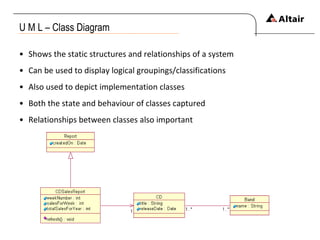
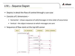
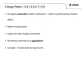
The document discusses the principles of object-oriented programming (OOP) concepts and their applications in software development, focusing on functionality, analysis, and design patterns. It outlines key OOP concepts such as inheritance, polymorphism, encapsulation, and composition, and explains their importance in creating maintainable and scalable solutions. Additionally, it introduces the Unified Modeling Language (UML) as a way to represent system functionality through various diagrams, including use-case and class diagrams.