Downloaded 224 times


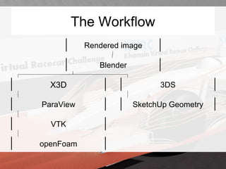
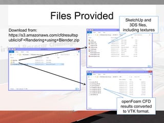

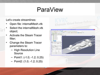

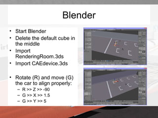

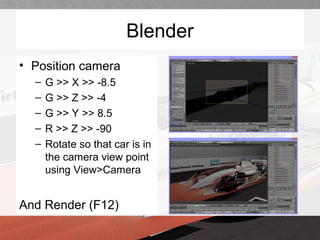
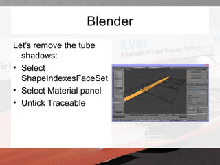

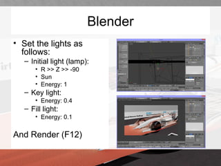
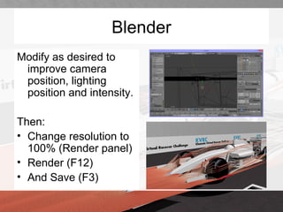


This document discusses using Blender to generate high resolution renders of openFoam CFD results. It outlines the workflow of exporting openFoam data to VTK format using ParaView, importing it into Blender along with 3D geometry files, positioning and lighting the scene, and rendering the final images. The key steps are converting CFD results to VTK, using ParaView to extract streamlines and export to X3D, importing files into Blender, aligning the geometry, adding lights, and rendering images of the CFD results visualized on the geometry.