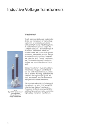
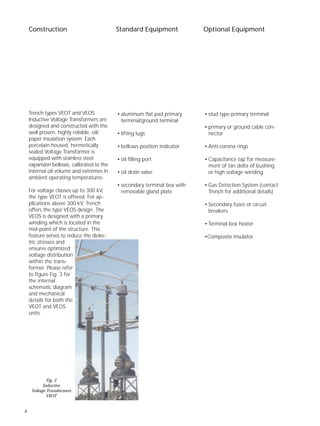
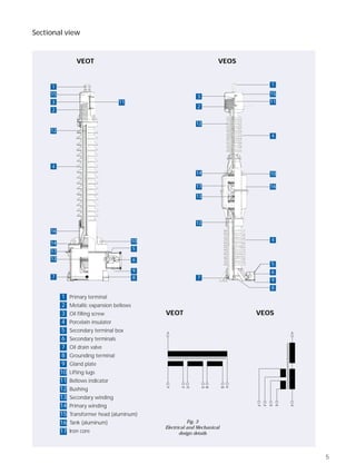
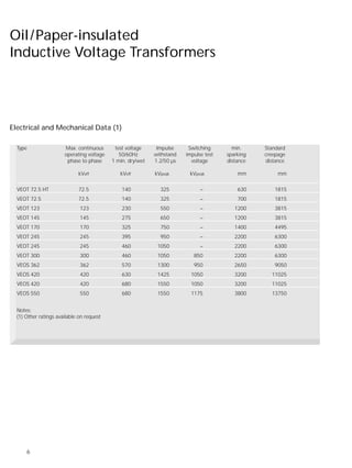
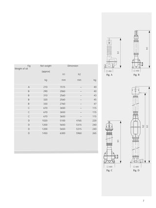
Inductive Voltage Transformers
Types VEOT and VEOS
2
Inductive Voltage Transformers
Introduction
Trench is a recognized world leader in the
design and manufacture of high voltage
equipment for application on electric
utility and high energy industrial systems.
As part of Trench's product scope, the
Company produces a diversified range of
Instrument Transformers which are
installed on 69-800 kV electrical systems.
Instrument Transformers include: Voltage
(Potential) Transformers (both inductive
and capacitive type), Current Transformers
and Combined Instrument Transformers
(voltage and current transformer in one
unit).
Voltage Transformers must convert trans-
mission class voltages to standardized
low and easily measurable values, which
will be used for metering, protection and
control of the high voltage system. As
such, the need for accurate and reliable
voltage transformation is essential.
This brochure will detail the features and
characteristics of types VEOT and VEOS
inductive type Voltage Transformers.
Please refer to Trench brochure E210 for
additional general information concerning
high voltage Instrument Transformers.
Fig. 1
Type VEOT 72,5(left) and
VEOT 245(right)
oil/paper Insulated
Voltage Transformers
3
• highly refined and processed
oil/paper insulation system
• low weight and minimum oil
volume
• use of high quality mineral oil,
PCB free, biological decomposi-
tion
• excellent seismic performance
as a consequence of optimized
designs of flanges, porcelain and
their interconnection
• excellent control of internal and
external insulation stresses
through the use of a proprietary
finely graded bushing system
• essentially unaffected by stray
external magnetic fields
• hermetically sealed stainless steel
metallic bellows for units rated
123 kV and above
• welded housings sealed without
screws
Features
• Meet all IEC and ANSI metering
and protection classes
(other standards on request)
• Standard thermal burden
ratings of 2000 - 2500 VA
(higher on request)
• Quality Assurance in
accordance with ISO 9001
• stable accuracy over a long period
of time
• perfect transient performance
• suitable for line discharging
• exclusive use of corrosion-resistant
materials
• explosion resistant by
- insulating system with high
reliability
- fine graded bushing
- weak point in the aluminium
head and tank castings and
the metallic bellows serving as
pressure release device
• successful field experience since
the manufacture of the first volt-
age transformer in 1926
• maintenance free during a long
life time of more than 30 years
• composite insulator available on
request
4
Trench types VEOT and VEOS
Inductive Voltage Transformers are
designed and constructed with the
well proven, highly reliable, oil/
paper insulation system. Each
porcelain housed, hermetically
sealed Voltage Transformer is
equipped with stainless steel
expansion bellows, calibrated to the
internal oil volume and extremes in
ambient operating temperatures.
For voltage classes up to 300 kV,
the type VEOT is offered. For ap-
plications above 300 kV, Trench
offers the type VEOS design. The
VEOS is designed with a primary
winding which is located in the
mid-point of the structure. This
feature serves to reduce the dielec-
tric stresses and
ensures optimized
voltage distribution
within the trans-
former. Please refer
to figure Fig. 3 for
the internal
schematic diagram
and mechanical
details for both the
VEOT and VEOS
units.
Construction
• aluminum flat pad primary
terminal/ground terminal
• Iifting lugs
• bellows position indicator
• oil filling port
• oil drain valve
• secondary terminal box with
removable gland plate
• stud type primary terminal
• primary or ground cable con-
nector
• Anti-corona rings
• Capacitance tap for measure-
ment of tan delta of bushing
or high voltage winding
• Gas Detection System (contact
Trench for additional details)
• Secondary fuses or circuit
breakers
• Terminal box heater
•Composite insulator
Standard Equipment Optional Equipment
Fig. 2
Inductive
Voltage Transformers
VEOT
5
Primary terminal
Metallic expansion bellows
Oil filling screw
Porcelain insulator
Secondary terminal box
Secondary terminals
Oil drain valve
Grounding terminal
Gland plate
Lifting lugs
Bellows indicator
Bushing
Secondary winding
Primary winding
Transformer head (aluminum)
Tank (aluminum)
Iron core
VEOT VEOS
12
Sectional view
A
1a 1n 2a 2n da Ndn
A
N1a 1n 2a 2n
VEOSVEOT
Fig. 3
Electrical and Mechanical
design details
3
1
15
2
4
16
14
17
13
7
10
5
6
9
8
1
2
3
4
5
6
7
8
9
10
11
12
13
14
15
16
17
11
12
3
2
14
17
13
12
1
15
11
4
10
16
4
7
5
6
9
8
6
Oil/Paper-insulated
Inductive Voltage Transformers
Electrical and Mechanical Data (1)
Type Max. continuous test voltage Impulse Switching min. Standard
operating voltage 50/60Hz withstand impulse test sparking creepage
phase to phase 1 min. dry/wet 1.2/50 µs voltage distance distance
kVeff kVeff kVpeak kVpeak mm mm
VEOT 72.5 HT 72.5 140 325 – 630 1815
VEOT 72.5 72.5 140 325 – 700 1815
VEOT 123 123 230 550 – 1200 3815
VEOT 145 145 275 650 – 1200 3815
VEOT 170 170 325 750 – 1400 4495
VEOT 245 245 395 950 – 2200 6300
VEOT 245 245 460 1050 – 2200 6300
VEOT 300 300 460 1050 850 2200 6300
VEOS 362 362 570 1300 950 2650 9050
VEOS 420 420 630 1425 1050 3200 11025
VEOS 420 420 680 1550 1050 3200 11025
VEOS 550 550 680 1550 1175 3800 13750
Notes:
(1) Other ratings available on request
7
Fig Net weight Dimension
Weight of oil
(approx)
h1 h2
kg mm mm kg
A 210 1515 – 40
B 290 2060 – 40
B 310 2560 – 43
B 320 2560 – 45
B 330 2760 – 47
C 670 3650 – 115
C 670 3650 – 115
C 670 3650 – 115
D 1020 5100 4765 220
D 1200 5650 5315 240
D 1450 6300 5960 265
Fig. A
Fig. C Fig. D
Fig. B
Ⅺ 450
Ⅺ 600 Ⅺ 600
h1
h1
h1
h1
h2
Ⅺ 450
Subject to change without notice
04.2000
E211.21
www.trenchgroup.com
Trench Austria GmbH
Paschinger Strasse 49, Postfach 13
A-4060 Linz-Leonding/Austria
Phone +43.732.6793-0
Fax +43.732.671341
E-Mail sales@TrenchAustria.at
Trench Brasil LTDA
Via Expressa de Contagem, 2685
CEP 32370-485
Cpmtagem, MG - Brasil
Phone 55. 31. 391-5959
Fax 55. 31. 391-1828
E-Mail
trenchbrasil@ca.trenchgroup.com
Trench Limited
Coil Product Division
71 Maybrook Drive, Scarborough
Ontario, Canada M1V 4B6
Phone (416) 298-8108
Fax (416) 298-2209
E-Mail sales@ca.trenchgroup.com
Trench Limited
Instrument Transformer Division
390 Midwest Road, Scarborough
Ontario, Canada M1P 3B5
Phone (416) 751-8570
Fax (416) 751-6952
E-Mail sales@ca.trenchgroup.com
Trench France S.A.
16, rue du Général Cassagnou
B.P. 70
F- 68302 St-Louis Cedex/France
Phone +33.3.89 70 23 23
Fax +33.3.89 67 26 63
E-Mail sales@trench-france.com
Trench Germany GmbH
Nürnberger Strasse 199
96050 Bamberg/Germany
Phone +49.951.1803-0
Fax +49.951.1803-224
E-Mail sales@trench.de
Trench Switzerland AG
Lehenmattstrasse 353
CH - 4028 Basel/Switzerland
Phone +41.61.315 5111
Fax +41.61.315 59 00
E-Mail sales@trench.ch

Inductive voltage transformers

  • 1.
  • 2.
    2 Inductive Voltage Transformers Introduction Trenchis a recognized world leader in the design and manufacture of high voltage equipment for application on electric utility and high energy industrial systems. As part of Trench's product scope, the Company produces a diversified range of Instrument Transformers which are installed on 69-800 kV electrical systems. Instrument Transformers include: Voltage (Potential) Transformers (both inductive and capacitive type), Current Transformers and Combined Instrument Transformers (voltage and current transformer in one unit). Voltage Transformers must convert trans- mission class voltages to standardized low and easily measurable values, which will be used for metering, protection and control of the high voltage system. As such, the need for accurate and reliable voltage transformation is essential. This brochure will detail the features and characteristics of types VEOT and VEOS inductive type Voltage Transformers. Please refer to Trench brochure E210 for additional general information concerning high voltage Instrument Transformers. Fig. 1 Type VEOT 72,5(left) and VEOT 245(right) oil/paper Insulated Voltage Transformers
  • 3.
    3 • highly refinedand processed oil/paper insulation system • low weight and minimum oil volume • use of high quality mineral oil, PCB free, biological decomposi- tion • excellent seismic performance as a consequence of optimized designs of flanges, porcelain and their interconnection • excellent control of internal and external insulation stresses through the use of a proprietary finely graded bushing system • essentially unaffected by stray external magnetic fields • hermetically sealed stainless steel metallic bellows for units rated 123 kV and above • welded housings sealed without screws Features • Meet all IEC and ANSI metering and protection classes (other standards on request) • Standard thermal burden ratings of 2000 - 2500 VA (higher on request) • Quality Assurance in accordance with ISO 9001 • stable accuracy over a long period of time • perfect transient performance • suitable for line discharging • exclusive use of corrosion-resistant materials • explosion resistant by - insulating system with high reliability - fine graded bushing - weak point in the aluminium head and tank castings and the metallic bellows serving as pressure release device • successful field experience since the manufacture of the first volt- age transformer in 1926 • maintenance free during a long life time of more than 30 years • composite insulator available on request
  • 4.
    4 Trench types VEOTand VEOS Inductive Voltage Transformers are designed and constructed with the well proven, highly reliable, oil/ paper insulation system. Each porcelain housed, hermetically sealed Voltage Transformer is equipped with stainless steel expansion bellows, calibrated to the internal oil volume and extremes in ambient operating temperatures. For voltage classes up to 300 kV, the type VEOT is offered. For ap- plications above 300 kV, Trench offers the type VEOS design. The VEOS is designed with a primary winding which is located in the mid-point of the structure. This feature serves to reduce the dielec- tric stresses and ensures optimized voltage distribution within the trans- former. Please refer to figure Fig. 3 for the internal schematic diagram and mechanical details for both the VEOT and VEOS units. Construction • aluminum flat pad primary terminal/ground terminal • Iifting lugs • bellows position indicator • oil filling port • oil drain valve • secondary terminal box with removable gland plate • stud type primary terminal • primary or ground cable con- nector • Anti-corona rings • Capacitance tap for measure- ment of tan delta of bushing or high voltage winding • Gas Detection System (contact Trench for additional details) • Secondary fuses or circuit breakers • Terminal box heater •Composite insulator Standard Equipment Optional Equipment Fig. 2 Inductive Voltage Transformers VEOT
  • 5.
    5 Primary terminal Metallic expansionbellows Oil filling screw Porcelain insulator Secondary terminal box Secondary terminals Oil drain valve Grounding terminal Gland plate Lifting lugs Bellows indicator Bushing Secondary winding Primary winding Transformer head (aluminum) Tank (aluminum) Iron core VEOT VEOS 12 Sectional view A 1a 1n 2a 2n da Ndn A N1a 1n 2a 2n VEOSVEOT Fig. 3 Electrical and Mechanical design details 3 1 15 2 4 16 14 17 13 7 10 5 6 9 8 1 2 3 4 5 6 7 8 9 10 11 12 13 14 15 16 17 11 12 3 2 14 17 13 12 1 15 11 4 10 16 4 7 5 6 9 8
  • 6.
    6 Oil/Paper-insulated Inductive Voltage Transformers Electricaland Mechanical Data (1) Type Max. continuous test voltage Impulse Switching min. Standard operating voltage 50/60Hz withstand impulse test sparking creepage phase to phase 1 min. dry/wet 1.2/50 µs voltage distance distance kVeff kVeff kVpeak kVpeak mm mm VEOT 72.5 HT 72.5 140 325 – 630 1815 VEOT 72.5 72.5 140 325 – 700 1815 VEOT 123 123 230 550 – 1200 3815 VEOT 145 145 275 650 – 1200 3815 VEOT 170 170 325 750 – 1400 4495 VEOT 245 245 395 950 – 2200 6300 VEOT 245 245 460 1050 – 2200 6300 VEOT 300 300 460 1050 850 2200 6300 VEOS 362 362 570 1300 950 2650 9050 VEOS 420 420 630 1425 1050 3200 11025 VEOS 420 420 680 1550 1050 3200 11025 VEOS 550 550 680 1550 1175 3800 13750 Notes: (1) Other ratings available on request
  • 7.
    7 Fig Net weightDimension Weight of oil (approx) h1 h2 kg mm mm kg A 210 1515 – 40 B 290 2060 – 40 B 310 2560 – 43 B 320 2560 – 45 B 330 2760 – 47 C 670 3650 – 115 C 670 3650 – 115 C 670 3650 – 115 D 1020 5100 4765 220 D 1200 5650 5315 240 D 1200 5650 5315 240 D 1450 6300 5960 265 Fig. A Fig. C Fig. D Fig. B Ⅺ 450 Ⅺ 600 Ⅺ 600 h1 h1 h1 h1 h2 Ⅺ 450
  • 8.
    Subject to changewithout notice 04.2000 E211.21 www.trenchgroup.com Trench Austria GmbH Paschinger Strasse 49, Postfach 13 A-4060 Linz-Leonding/Austria Phone +43.732.6793-0 Fax +43.732.671341 E-Mail sales@TrenchAustria.at Trench Brasil LTDA Via Expressa de Contagem, 2685 CEP 32370-485 Cpmtagem, MG - Brasil Phone 55. 31. 391-5959 Fax 55. 31. 391-1828 E-Mail trenchbrasil@ca.trenchgroup.com Trench Limited Coil Product Division 71 Maybrook Drive, Scarborough Ontario, Canada M1V 4B6 Phone (416) 298-8108 Fax (416) 298-2209 E-Mail sales@ca.trenchgroup.com Trench Limited Instrument Transformer Division 390 Midwest Road, Scarborough Ontario, Canada M1P 3B5 Phone (416) 751-8570 Fax (416) 751-6952 E-Mail sales@ca.trenchgroup.com Trench France S.A. 16, rue du Général Cassagnou B.P. 70 F- 68302 St-Louis Cedex/France Phone +33.3.89 70 23 23 Fax +33.3.89 67 26 63 E-Mail sales@trench-france.com Trench Germany GmbH Nürnberger Strasse 199 96050 Bamberg/Germany Phone +49.951.1803-0 Fax +49.951.1803-224 E-Mail sales@trench.de Trench Switzerland AG Lehenmattstrasse 353 CH - 4028 Basel/Switzerland Phone +41.61.315 5111 Fax +41.61.315 59 00 E-Mail sales@trench.ch