Downloaded 14 times


![INTRODUCTION ABOUT PROJECT
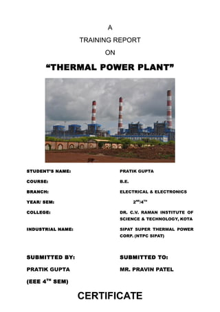
Sipat Super Thermal Power Station is located at Sipat in Bilaspur district in state of Chhattisgarh.
The power plant is one of the coal based power plants of NTPC. The coal for the power plant is
sourced from Dipika Mines of South Eastern Coalfields Limited.
The project has an installed capacity of 2980 MW consisting of two stages, stage one which got
commissioned late was of 3 units of 660 MW each involving super-critical boilers technology and
stage two consisted of 2 units of 500 MW each.
Stage Unit Number Installed Capacity (MW) Date of Commissioning Status
1st 1 660 2011 June Running
1st 2 660 2011 December Running
1st 3 660 2012 June [1]
Running
2nd 4 500 2007 May Running
2nd 5 500 2008 August Running
Total Five 2980
Sipat
Sipat' is a small developing town, approximately 22 kilometers away from Bilaspur, Chhattisgarh, the
second largest city in Chhattisgarh. It has been in news due to setup of new power plant by NTPC
Limited in that area. The project was started on 2001 by Indian former Prime Minister Mr. Atal Bihari
Vajpayee.NTPC Sipat has total installed capacity of 2980 MW.NTPC Sipat has two stages: Stage-I
comprises 3 units of 660MW each and Stage-II comprises 2 units of 500MW each. The thermal power
generation in NTPC sipat Stage-II is based on "Super Critical Boiler Technology" which is the
advanced technology in thermal power generation. NTPC Limited has helped this town in developing
by providing business prospective in that area and by providing education, healthcare facilities.](https://image.slidesharecdn.com/ntpc-131113070238-phpapp02-140708103421-phpapp01/85/Ntpc-131113070238-phpapp02-8-320.jpg)


This document provides a training report on a thermal power plant. It summarizes the key components and processes of the coal handling plant at NTPC Sipat Super Thermal Power Station. The coal handling plant conveys coal from railway wagons to bunkers using various equipment like wagon tipplers, paddle feeders, vibrating feeders, and conveyor belts. The coal is crushed and sized to less than 20mm. Magnetic separators and metal detectors are used to remove foreign particles from the coal before it is stacked and reclaimed to bunkers.