This document provides a summary of Maneeshkumar Shukla's 4-week summer training at the 3x210 MW Anpara 'A' Thermal Power Station in Anpara, Sonbhadra, Uttar Pradesh, India. It includes an acknowledgement of those who supported the training, a certificate of completion signed by the supervising engineer, and sections describing the power production process involving coal handling, combustion, steam generation, turbine operation, and water management at the facility.
Summer training report at uttpar pradesh rajay viduat utpadan nigam ...Navin Pathak
The document summarizes a summer training report submitted by a student at the Uttar Pradesh Rajya Vidhyut Utpadan Nigam Limited thermal power plant in Anpara, Sonebhadra, India. The report provides an overview of the power plant, including its layout, products like electricity and ash, and the production process. It also includes a chronological training diary of the student's activities during the summer, such as familiarizing with the plant components and studying the turbines. The production process follows the Rankine cycle, where coal is combusted to produce steam that drives the turbine and generates electricity.
This training report summarizes Pratik Gupta's vocational training at the SIPAT Super Thermal Power Project. It provides details on the production of electricity at a thermal power plant. Coal is ground and blown into boilers where it burns, heating water in tubes to produce high pressure steam. The steam powers turbines connected to generators, producing electricity. The steam is then condensed back into water in condensers to be reused in the cycle. The report outlines the key components and processes involved in electricity generation at a coal-fired thermal power station.
The Kota Super Thermal Power Station is a 1240MW coal power plant located in Kota, Rajasthan. It uses a steam turbine generator system fueled by coal. Coal is transported via a conveyor system to the boiler, where it is burned to produce steam that drives the turbine generator. The steam is then condensed in condensers using cooling water from the Chambal River. Fly ash from combustion is captured and can be used for products like cement or road construction. The power station began operating in 1983 and has since expanded in stages to its current capacity.
Thermal Power plant visit Report by Amit Hingeamit307
The document is an industrial visit report on Paras Thermal Power Plant in Akola, India. It provides an overview of the key components and processes of a coal-fired thermal power plant, including coal preparation, boilers, turbines, generators, condensers and cooling towers. Paras Thermal Power Plant is one of the oldest power plants owned by Maharashtra State Power Generation Company, with the first units installed in 1961. It has since been upgraded with newer 250MW units. The report serves to explain the functioning and technical aspects of thermal power generation to students who visited the plant.
TPS training report Gandhinagar, coal base power plant vishal patel
This document provides an overview of a practical training report submitted by two students for their Bachelor of Engineering degree in Mechanical Engineering. It includes an introduction to the power plant where they conducted their training, describing its key components like the boiler, coal mill, draught system and more. Diagrams are provided to illustrate the typical processes used in a coal-fired thermal power station.
This document provides an overview of a practical training seminar presented to the CompuCom Institute of Information Technology & Management Jaipur on NTPC Kahalgaon power station. It discusses the history and setup of NTPC as India's largest power company. The summary describes the three step process of generating electricity through: 1) converting coal to steam, 2) using steam to power turbines for mechanical energy, and 3) generating electricity through power stations and distributing it via transmission lines. Key electrical equipment at the power station like alternators and transformers are also outlined.
The document provides a training report on the Kalisindh Thermal Power Project in Jhalawar, Rajasthan. It discusses that the power plant has two units that generate 600 MW each for a total output of 1200 MW. It then describes the various processes involved in coal-fired thermal power generation including the coal handling plant, boiler, turbine, generator and other key components. The report also discusses the plant overview, principle of operation, efficiency and concludes with references.
The document is a presentation on a practical training and industrial visit to the Kota Super Thermal Power Station in India. It summarizes the key details of the power station in 3 points:
1) The power station has a total installed capacity of 1240 MW and uses coal as its fuel source, sourced from nearby mines. It employs a steam turbine generator system to convert the heat from combustion into electrical power.
2) The power station's operations include a coal handling plant to receive and transport coal via rail, a boiler to produce high pressure steam from coal combustion, a steam turbine to convert steam power into rotational energy, and generators to convert this into electrical power.
3) Ash handling is also
The document provides an overview of the coal handling plant (CHP) at Anpara Thermal Power Station in Uttar Pradesh, India. It discusses the basic processes in a CHP, including receiving coal via rail or conveyor, crushing the coal, transporting it to bunkers via conveyor belts and trippers, and storing excess coal via stacking and reclaiming. The CHP handles coal from receipt to transporting it to boilers and bunkers. It also processes raw coal to the required size for boiler operations. The CHP faces various challenges like design issues due to lower quality coal, problems during monsoon season, and mechanical failures of equipment.
A best ppt on kota super thermal power stationNaveen Kumar
Kota Super Thermal Power Station (KSTPS) is located in Kota, Rajasthan. It has a total generation capacity of 1240 MW across 7 stages of power production. Coal is used as fuel and is supplied by Coal India Limited. The presentation discusses the general layout and various key components of the power plant including the coal handling plant, boiler, ash handling plant, steam turbine, electricity generator, cooling system, transformer, and control panel. KSTPS uses a water tube boiler and produces electricity through a steam turbine connected to a generator.
Ntpc unchahar summer or vocational training pptaryan5808
NTPC Unchahar power plant has a total installed capacity of 1050MW from its coal-based thermal units. It sources coal from nearby mines and water from the Sharda Sahayak canal. The presentation summarized the key processes and components of a thermal power plant including coal handling, boiler, turbine, generator, condenser, cooling tower, and ash handling. The main departments of the plant work together to convert the heat energy from coal combustion into electrical energy through these processes.
This training report provides an overview of the 2x600 MW Kalisindh Thermal Power Project located in Jhalawar, Rajasthan. The report discusses the plant layout and various systems involved in power generation including the coal handling system, raw water and cooling systems, steam generation train, transformers, ash handling plant, switchyard and control room. It also includes the objectives, methodology adopted and conclusions from the training. Single line diagrams and technical specifications of major equipment are provided.
Ntpc (national thermal power corporation) sipat mechanical vocational trainin...haxxo24
This document is a vocational training report submitted by Ritesh Patnaik after completing a 30-day training at the National Thermal Power Corporation plant in Sipat, Chhattisgarh, India. The report provides an overview of the key components and systems at the NTPC Sipat Super Thermal Power Project, including the steam turbine, generator, condenser, boiler, cooling towers, and pollution control devices. It also describes the basic Rankine cycle that is used to convert heat into electrical power at thermal power plants.
The document provides an overview of a coal-based thermal power plant presented by Shivam Kumar. It describes the key components of the plant including the coal handling plant, boiler and auxiliaries like superheaters and economizers, condenser, cooling towers, feedwater heaters, turbines, deaerator, and electrostatic precipitator. The plant has a capacity of 1500MW in stage 1 and is located in Haryana, utilizing coal delivered by rail to generate electricity through the Rankine cycle process in its boilers and turbines.
Ntpc (national thermal power corporation) sipat mechanical vocational trainin...haxxo24
This document is a summer training project report submitted by Dinesh Kumar, a mechanical engineering student, on his vocational training at the National Thermal Power Corporation Sipat power plant in Chhattisgarh, India. The report provides an overview of NTPC Sipat, including its location, installed capacity, use of supercritical technology, and environmental management practices. It also describes the basic Rankine cycle used in thermal power plants, the major sub-systems of a power plant such as the coal handling plant, mills, water treatment plant and boiler, and includes diagrams of a typical power plant layout and the interior of a bowl mill.
NTPC was established in 1975 by the Government of India to address growing power demand. It is now the largest power generating company in India with over 30 GW of installed capacity from coal, gas, hydro, and renewable sources. NTPC started with thermal power plants and has expanded into various power generation technologies and business areas. The document provides details on NTPC's thermal power plants across India, including their locations and installed capacities.
This document provides a summary of a seminar on summer vocational training at NTPC thermal power plants. It discusses the key components of a thermal power plant including coal handling, pulverizing, boilers, turbines, generators, condensers, and ash handling. It also describes various equipment like ball mills used in pulverizing coal and control and instrumentation labs that monitor critical parameters. Finally, it lists some major thermal power plants in Rajasthan and references used in preparing the seminar.
The document expresses gratitude to various people who helped with a vocational training project at a thermal power plant. It thanks the officials who oversaw the project, the power plant staff who provided assistance, and the author's parents for their support in completing the project successfully.
The document discusses the Kalisindh Thermal Power Station (KaTPP) located in Jhalawar district, Rajasthan, India. It has an installed capacity of 1200 MW from two 600 MW coal-based units. Coal is sourced from nearby mines and water comes from the Kalisindh Dam. The coal is crushed and fed into boilers to produce steam, which powers turbines connected to generators to produce electricity. The electricity is transmitted through a switchyard before being distributed.
Kalisindh Super Thermal Power Plant,Jhalawar,Rajasthan ,ReportMAHENDRA MEENA
This document provides information about Mahendra Kumar Meena's 4-week vocational training at the Kalisindh Super Thermal Power Project in Jhalawar, Rajasthan from May 18th to June 17th. It includes an acknowledgements section thanking those who helped with the training. The content section outlines topics that will be covered related to the power project including introductions, salient features, cooling systems, steam power generation, water treatment and demineralized water.
The document provides an overview of a thermal power plant training project conducted at the Jamshoro Thermal Power Station in Pakistan. It discusses the importance of practical training and familiarizing with real-world industrial scenarios. It also briefly outlines the various processes involved in power generation including steam generation, turbine generation, synchronization, and control and instrumentation. The report aims to cover all aspects of the power plant in detail to gain experience in electrical, mechanical, chemical and control/instrumentation departments.
This document summarizes a seminar on summer training at NTPC Ltd Shaktinagar power plant. It provides an overview of NTPC, describing that it is India's largest power company with over 29,000 MW of installed capacity across various coal and gas-fired power plants. It then describes the Shaktinagar power plant in more detail, including its 2000 MW installed capacity, coal source, beneficiary states, and unit sizes. It also includes simplified diagrams of the main components of a thermal power plant.
This document is a project report submitted by Sushant Kumar summarizing his one month vocational training at the Kanti Bijlee Utpadan Nigam Limited power plant. The report provides an overview of the plant's operations including the processes of generating electricity from coal, the main boiler and turbine components, and control systems used. It also describes the milling system for pulverizing coal and the light up process for initially igniting the coal furnace.
The document provides information about Anil Jadon's industrial training at the NTPC power plant in Faridabad. It discusses the company NTPC, describes the Faridabad plant and its 432 MW capacity powered by natural gas. It explains the basic working of the power plant, from burning natural gas in the gas turbine to generating electricity. It also discusses the electrical systems, distribution of electricity, control and instrumentation, advantages of natural gas, and precautions taken at the plant. The training helped clear Anil's concepts and understand how electricity is generated at the large scale, efficient Faridabad plant.
This internship report summarizes a summer internship at the Gandhinagar Thermal Power Station in Gujarat, India. The internship included visits to four sections: the coal plant electrical maintenance department, the testing department, the switchyard, and the electrical maintenance department. The interns learned about the coal handling and storage process, various types of electrical protection systems, equipment testing procedures, and components of the power plant such as the boiler and turbines. Overall, the internship provided hands-on experience in key areas of power generation and an opportunity to gain practical knowledge of power station operations.
A Presentation on Kota Super Thermal Power StationLekhraJ Meena
The document provides information about the Kota Super Thermal Power Plant in India including its establishment, generation capacity, units and their installation details. It describes the main components of the plant including the coal handling plant, boiler, superheater, steam turbine, generator, water treatment plant, ash handling plant and control room. The coal handling plant section explains the wagon unloading, crushing and conveying systems. The document also provides diagrams to illustrate the layout and processes of the power plant.
1. The document describes NTPC Sipat power plant which has a total installed capacity of 2980 MW from 3 units of 660 MW and 2 units of 500 MW.
2. The 500 MW units use supercritical boiler technology which allows higher efficiencies between 40-42% compared to subcritical plants.
3. The plant sources coal from Dipika mines and water from Hasdeo barrage to operate its steam cycle.
The document provides information about the generation of thermal power at NTPC Dadri power plant. It discusses how coal is burned in boilers to generate high pressure steam which is used to spin turbines connected to generators to produce electricity. The key components of the thermal power plant discussed are the boiler, turbine, condenser, cooling towers and electrical equipment like transformers. It also describes the coal handling process and techniques used to handle ash waste from coal combustion like electrostatic precipitators.
1. The document provides an acknowledgement and thanks to various individuals and departments at NTPC Tanda for allowing the training and providing support and knowledge.
2. It then outlines the content which will be covered, including a brief description of the Tanda thermal project, production of electricity, description of the thermal plant, basic cycle of a power plant, control and instrumentation unit, and important equipment of the plant.
3. It begins describing the Tanda thermal project, providing its geographical location, features such as its installed capacity and suppliers, and performance metrics like its designed boiler efficiency.
The document provides an overview of the coal handling plant at Anpara Thermal Power Station. It discusses the process of receiving coal via various transportation methods and processing it through primary and secondary crushers to the required size before storing it in bunkers. It also mentions the electrical equipment used in the coal handling plant like breakers, motors, and describes the general working process of crushing, conveying, and storing coal until it is sent to the coal mills for combustion in the boiler furnace. A layout diagram of the typical coal handling plant is also included.
This document provides an overview of the processes involved in a thermal power plant. It begins by explaining that thermal power plants convert chemical energy stored in fuels like coal into heat energy and then electrical energy. It describes the basic energy conversions that occur in the boiler, turbine and generator. It then provides specific details about the Kalisindh Thermal Power Plant in Jhalawar, India, including its location, capacity and land acquisition. The document outlines the basic systems and processes within a thermal power plant, including coal handling, steam generation, power generation via turbines and generators, and electrical transmission. It provides diagrams illustrating the Rankine cycle and process flow within the plant.
NTPC Dadri power plant has an installed capacity of 2642 MW including 1820 MW from thermal units and 817 MW from gas units. It sources coal from Piparwara mine in Jharkhand and water from Upper Ganga Canal. The basic processes include coal handling, combustion in boilers to produce steam, steam passing through turbines to generate electricity, and condensation of steam in condensers. Key components are coal handling plant, boilers, turbines, condensers, cooling towers, ESPs for emissions control, and chimney. Fly ash is a byproduct that is used in construction materials.
A thermal power plant operates by burning coal to create steam, which spins turbines that drive generators to produce electricity. The thermal power plant uses various processes: coal is pulverized and blown into a boiler to create steam, which expands in a turbine to spin a generator. The steam is then condensed in a condenser and recycled to the boiler. Ash produced during combustion is collected by an electrostatic precipitator and disposed of properly. The plant's operations are controlled and monitored in a central control room.
The document provides information about Kolaghat Thermal Power Station located in West Bengal, India. It has six units totaling 1,260 MW capacity. The power plant uses a steam turbine process to convert the heat from burning coal into electrical energy. It describes the main equipment used including the coal handling plant, boiler, turbine, condenser, and electrical equipment like transformers and generators. The document provides technical specifications for many of the major components.
Bathinda thermal power plant mid semester reportLovesh Singla
The document describes the Guru Nanak Dev Thermal Power Plant located in Bathinda, India. It is a coal-based thermal power plant with four units that have a total installed capacity of 440MW. The plant receives coal via rail, which is then crushed and pulverized before being burned in the boiler to produce steam. This steam powers a steam turbine which is connected to a generator, producing electricity. The plant helps meet the power demand of Punjab and provides local employment.
ELECTRICAL ENGINEERING THERMAL POWER PLANT Industrial ReportUtkarsh Chaubey
The document is an industrial training report submitted by Utkarsh Chaubey to Rajiv Gandhi Proudyogiki Vishwavidyalaya. It provides an overview of Utkarsh's training at the Shri Singaji Thermal Power Plant (SSTPP). The report includes sections on the power plant overview, the Rankine cycle used, classification of thermal power plants, typical components of a coal fired plant, site selection considerations, and descriptions of various systems within SSTPP such as the generator, switchyard, transformers, and safety measures.
it is the very important notes on :
1. Turbine
2. turbine component
3. princple of turbine
4.contruction of turbine
5.production process with hydroelectric and chp
The document provides information about Vikas Kr. Singh's summer training at the NTPC power plant in Dadri. It discusses the key details of the power plant, including its installed capacity of 2642 MW from thermal, gas, and solar sources. It describes the basic working of the thermal power generation process, from coal handling to power generation in the turbine and generator. It also summarizes the functions of important components in the plant like the boiler, turbine, condenser, cooling tower, and switchyard equipment.
The document provides information about the Indira Gandhi Thermal Power Plant located in Jharli, Jhajjar, Haryana. It is a 3x500MW coal-based thermal power plant established on 2,191 acres of land by Aravali Power Company Private Limited. The plant uses a steam turbine generator process to convert the thermal energy of coal into electrical energy, which is then transmitted through a 400kV transmission system. It describes the key components of a thermal power plant including the boiler, turbine, generator, condenser, and coal and ash handling systems.
Ntpc dadri thermal power plant & switchyardI.E.T. lucknow
The document provides information about a summer training program at the NTPC power plant in Dadri, India. It discusses the installed capacity of the plant, which includes 1820 MW of thermal capacity and 817 MW of gas capacity. It then describes the various components and processes within the thermal power station, including the coal handling plant, boiler, turbine, condenser, cooling tower, and electrical equipment. It also provides a brief overview of the switchyard station and some of its key electrical components.
The document provides an overview of the Mejia Thermal Power Station (MTPS) located in West Bengal, India. It is owned by the Damodar Valley Corporation and has a total installed capacity of 2340 MW generated from various units. The document describes the key components of the thermal power plant including the coal handling system, pulverizer, boiler, turbine, condenser, and switchyard. It also provides a step-by-step explanation of how coal is converted into electrical energy within the power station.
This document provides an overview of an industrial in-plant training report submitted by Batch-8 at the Dr. NARLA TATA RAO Thermal Power Station. It includes an acknowledgment, index, abstract on thermal power and coal, introduction to the power station, purpose of the visit, working of the power station, details of the units, and descriptions of the coal handling plant, boiler, and boiler auxiliaries like the economizer and superheater. The report aims to provide trainees knowledge about the practical workings of a thermal power generation plant through their visit.
This document provides an overview of how a thermal power plant works. It describes the key components and processes, including how coal is converted to steam to drive turbines and generate electricity. The main equipment discussed are the coal handling plant, pulverizing plant, boiler, air preheater, economizer, turbine, condenser, cooling towers, and ash handling plant. Advantages of thermal power include inexpensive fuel and ability to install anywhere, while disadvantages are air pollution and high maintenance/operational costs.
The document provides an overview of the Mejia Thermal Power Station (MTPS) in West Bengal, India. It discusses:
1. MTPS is operated by Damodar Valley Corporation and has a total installed capacity of 2340 MW generated from various units.
2. The power plant layout includes the main equipment used in the generation process such as the coal handling plant, boiler, turbine, condenser, and cooling towers.
3. The stepwise operation begins with coal being burned in the boiler to produce high pressure steam, which is then used to rotate the turbine and generate electricity via the alternator.
A thermal power station uses coal to generate steam, which spins turbines that create electrical power. Coal is pulverized and burned to heat water and create steam. The steam spins turbines connected to generators, producing electricity. The steam is then condensed back into water and recycled through the system. Thermal power stations use various pumps, fans, condensers and other equipment to efficiently convert the energy in coal into electrical power for transmission and distribution.
National Thermal Power Corporation (NTPC) is India's largest power producer, with over 29,000 MW of installed capacity from coal, gas, and joint venture power stations across India. The Badarpur Thermal Power Station near Delhi has a 705 MW capacity and utilizes a coal conveyor, pulverizer, boiler, steam turbine, generator, and other components in its power generation process. The boiler burns pulverized coal to produce high temperature steam that drives the steam turbine and generator, producing electricity.
Bharat Heavy Electricals Limited (BHEL) is India's largest power equipment manufacturer and 12th largest globally. It has been in operation for over 50 years and has manufactured over 72% of India's total power generation capacity. BHEL exports products and services to over 70 countries. The document discusses BHEL's involvement in the 2x500 MW Durgapur Steel Thermal Power Station located in West Bengal, which it constructed on a turnkey basis for owner Damodar Valley Corporation. It then provides details on the power plant layout and components, including the boiler, turbine, generator, and cooling system.
The Antyodaya Saral Haryana Portal is a pioneering initiative by the Government of Haryana aimed at providing citizens with seamless access to a wide range of government services
Jennifer Schaus and Associates hosts a complimentary webinar series on The FAR in 2024. Join the webinars on Wednesdays and Fridays at noon, eastern.
Recordings are on YouTube and the company website.
https://www.youtube.com/@jenniferschaus/videos
Donate to charity during this holiday seasonSERUDS INDIA
For people who have money and are philanthropic, there are infinite opportunities to gift a needy person or child a Merry Christmas. Even if you are living on a shoestring budget, you will be surprised at how much you can do.
Donate Us
https://serudsindia.org/how-to-donate-to-charity-during-this-holiday-season/
#charityforchildren, #donateforchildren, #donateclothesforchildren, #donatebooksforchildren, #donatetoysforchildren, #sponsorforchildren, #sponsorclothesforchildren, #sponsorbooksforchildren, #sponsortoysforchildren, #seruds, #kurnool
A Guide to AI for Smarter Nonprofits - Dr. Cori Faklaris, UNC CharlotteCori Faklaris
Working with data is a challenge for many organizations. Nonprofits in particular may need to collect and analyze sensitive, incomplete, and/or biased historical data about people. In this talk, Dr. Cori Faklaris of UNC Charlotte provides an overview of current AI capabilities and weaknesses to consider when integrating current AI technologies into the data workflow. The talk is organized around three takeaways: (1) For better or sometimes worse, AI provides you with “infinite interns.” (2) Give people permission & guardrails to learn what works with these “interns” and what doesn’t. (3) Create a roadmap for adding in more AI to assist nonprofit work, along with strategies for bias mitigation.
Preliminary findings _OECD field visits to ten regions in the TSI EU mining r...OECDregions
Preliminary findings from OECD field visits for the project: Enhancing EU Mining Regional Ecosystems to Support the Green Transition and Secure Mineral Raw Materials Supply.
RFP for Reno's Community Assistance CenterThis Is Reno
Property appraisals completed in May for downtown Reno’s Community Assistance and Triage Centers (CAC) reveal that repairing the buildings to bring them back into service would cost an estimated $10.1 million—nearly four times the amount previously reported by city staff.
Abiy Berehe - Texas Commission on Environmental Quality Updates
Complete report
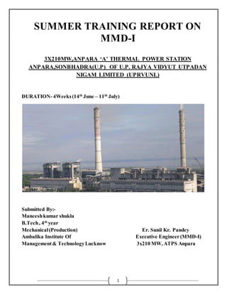
1. 1
SUMMER TRAINING REPORT ON
MMD-I
3X210MW,ANPARA ‘A’ THERMAL POWER STATION
ANPARA,SONBHADRA(U.P) OF U.P. RAJYA VIDYUT UTPADAN
NIGAM LIMITED (UPRVUNL)
DURATION- 4Weeks(14th
June – 11th
July)
Submitted By:-
Maneeshkumar shukla
B.Tech, 4th
year
Mechanical(Production) Er. Sunil Kr. Pandey
Ambalika Institute Of Executive Engineer(MMD-I)
Management& TechnologyLucknow 3x210 MW, ATPS Anpara
2. 2
ACKNOWLEDGEMENT
I wish to extend my deepest gratitude to all the respected persons who helped me in
successefully completing the four week summer training at Anpara ‘A’ Thermal power
station , Anpara Sonbhadra (UPRVUNL)
I thank heartily and pay my regards to the management of Anpara ‘A’ Thermal
power station Anpara, Sonbhadra (UPRVUNL), particularly Mr. Sunil Kr. Pandey
(Executive Engineer MMD-I ,A.T.P.S)Who allowed me to have my training in UPRVUNL
, Anpara, Sonbhadra. And I would also like to thank Mr Algu Ram & Mr. Arun Kumar
(Junior Engineer MMD-I ,A.T.P.S)fortheir humble and able guidance and interest shown
by them in an amiable and helpful manner throughout my training period .
And last but not least , I thank all the technicians and workers throughout the plant
who helped me have a better understanding of working of machines and process.
Submitted By:-
Maneesh kumar Shukla
B.Tech 4th year ,Mechanical Engg.
A.I.M.T Lucknow
3. 3
CERTIFICATE
This is to certify that MANEESH KUMAR SHUKLA student of Mechanical Engineering
from Ambalika Institute of Engineering & Technology, Lucknow has carried out his
summer training work during “14th jun – 11th july” presented in this report entitled
“(ANPARA THERMAL POWER PROJECT ANPARA)” under The supervision of
Er.Sunil Kr. Pandey (EXECUTIVE ENGINEER M.M.D-I ATPS)and his entire team.
Submitted By:-
Maneesh kumar Shukla
4. 4
ABSTRACT
A thermal power station is a power plant in which the prime mover is steam driven. Water
is heated, turns into steam and spins a steam turbine which drives an electrical generator.
After it passes through the turbine, the steam is condensed in a condenser and recycled to
where it was heated; this is known as a Rankine cycle. The greatest variation in the design
of thermal power stations is due to the different fuel sources. Some prefer to use the term
energy center because such facilities convert forms of heat energy into electricity. Some
thermal power plant also deliver heat energy for industrial purposes, for district heating, or
for desalination of water as well as delivering electrical power. A large part of human CO2
emissions comes from fossil fueled thermal power plants; efforts to reduce these outputs are
various and widespread.
At present 54.09% or 93918.38 MW (Data Source CEA, as on 31/03/2011) of total
electricity production in India is from Coal Based Thermal Power Station. A coal based
thermal power plant converts the chemical energy of the coal into electrical energy. This is
achieved by raising the steam in the boilers, expanding it through the turbine and coupling
the turbines to the generators which converts mechanical energy into electrical energy.
5. 5
INTRODUCTION
The site of Anpara Thermal Power Station is situated at the border of Madhya Pradesh
and Uttar Pradesh at Southern most tip of district Sonbhadra in Uttar Pradesh and on the
left bank of Rihand reservoir along the national highway No. 51 near village Anpara & 3
K.M. from the existing Renusagar Thermal Power Station.
Given below are some of the salient feature of Anpara Power Project, (2630 M.W.)
1. Station Units- ATPP, BTPP & DTPP.
2. Capacity a) Transiently installed 2630 M.W
(Including Units) (3x210M.W.ATPP,2x500M.W.-
BTPP,2x500 M.W.- DTPP)
b) Effective 2630 M.W.
3. Land details a) Plant area acres-1035.65
b) Ash dump area acres-1534.928
c) Employee township acres-453.432
d) Labour colony acres-160.000
4. Cooling water a)Source of cooling water Rihand reservoir
b)Method of cooling Open Cycle
c) Cooling water Requirement -100000(ATPS),14000(BTPS)m3/hr
5. Fuel(Coal) a)Consumption 25000 metric ton/day
b)source Khadiya Mines and kakadi Mines
6. 6
THERMAL POWER STATION
In a power plant , the heat released by the combustion of coal produces steam in a
boiler at high pressure & temperature which when passes through steam turbine, gives
internal energy as mechanical energy. The steam turbine acts as a prime mover & drives
the electric generator (alternator).
Electricity is indispensable for the development of a vast developing country like
India. Anpara Thermal Power Project in this respect plays always a crucial role in power
generation.
In India, as of now about 65% electrical power is used is generated in Thermal
Plants. The remaining 35% comes from hydro stations. Coal is the fuel for most of the
steam plants the rest depends on Oil/ Natural gases & Nuclear fuels.
The generation capacity of A.T.P.S is 2630MW (3x210, 2x500 & 2x500). The whole
power station is divided into three subparts:-
1. ATPP (3x210)MW
2. BTPP (2x500)MW
3. DTPP (2x500)MW
The electrical equipments used in ATPP & DTPP is almost of BHEL while BTPP is
established by help of Japan .
The power is transmitted to the distant areas form 400KV bus bars for economic
considerations & for supplying power to the station & to connect the station from other
power stations operating in the region, a 132KV bus bars systemis also in the switchyard &
maintenance division of ATPP is equipped with advanced technical equipments & expert
manpower in technical fields so as to handle any emergency situation arising in the plant &
keep the supply reliably & safely.
8. 8
COAL HANDLING AND COMBUSTION
We take coal from northern coal field (NCL)through our MGR system (Railway) to
track hopper and transport it through conveyor belt to crusher house and crush it up to 25
mm in size.
Again transport it through conveyor belt to bowl mills. Excess coal is stacked in the
coal stockyard through conveyor belt pulverized coal is transported through pipes to boilers
burner to burn it in close area. Ash dust from boiler is collected in Electrostatic precipitator
(ESP) up to 98% to 99% to minimize the air pollution is & collected ash is transported to
ash dyke in the form of ash slurry through pipes.
We take de-mineralized water from D.M water plant to the boiler tubes to make it
super heated steam at 535degree C and 135atm. Pressure to run the system turbines which
function as prime movers from turbo generators. Electricity is exported to different part of
our country through 400KV transmission line.
There is no intermediate productand byproductin the process exceptwaste
product(burntcoal ash) which is not so harmful . even though we try to arrest ash dustby
different method ESP, dust extraction system and tallest chimney e tc.
10. 10
PRODUCTION OF SYSTEM
Coal from the coal wagons is unloaded in the coal handling plants track hopper. This
coal is transported up to the raw bunkers with the help of belt conveyor. Coal is transported
to the bowl mills by coal feeders. The coal is pulverized in the bowl mill, where it is
grinded to powder form. The mill consist of a round metallic table on which coal particles
falls . This table is rotated with the help of electric motor there are three large grinding
rollers which are spaced 1200 apart when there is no coal these forces to roller to rotate.
When the coal is fed to the table it packs up between rollers and tables and these forces to
rollers to rotate.
Coal is crushed by the crushing action between the rollers and the rotating table .
This crushed coal is taken away to the furnace through coal pipes with the help of hot and
cold air mixture from PA fan takes atmosphere air, apart of which is send to the air
preheaters for heating , while a part goes directly to the mills for temperature control.
Atmospheric air from FD fan is heated in the air heater and sent to the furnaces secondary
air for coal combustion in the boiler.
Water from the boiler feed pump passes through HP heaters, feed regulatory station,
economizer etc water through the drum passes through down corners and goes to the bottom
ring header. Water from the bottom ring header is divided to all the four sides of the
furnaces due to heat and density difference , the rises up on the water wall tubes . water is
partly converted to steam and water mixture is again taken to the boiler drum where steam
is separated from water . Water follows the same path while steam is sent to super heaters
for super heating. The super heaters are located inside the furnace and the steam is super
heated to 540 degree C and finally goes to turbine through CVS and cover control and
emergency stop valves.
Flue gases from the furnace are extracted by induced draft fan, which maintain
balance draft in the furnace with forced draft fan. Theses flue gases emit their heat energy to
various super heaters, LTSH, Economizer tubes, etc finally passes through air preheaters
and goes to ESP where ash particles are extracted. ESP consists of, metal plates, which are
electrically charged. Ash particles attract on these electrodes and coils so that they do not
pass through the chimney to pollute the atmosphere. Regular mechanical hammers blow
cause the falling of the accumulated ash to the bottom of the precipitator where they are
collected in a hopper for disposal. This ash mixed with water to form slurry and is pumped
to ash pond.
11. 11
POWER OF STEAM
In the boiler the steam pipe conveys steam to the turbine through stop valves and
through control valves that automatically regulate the supply of steam to the turbine. Stop
valves and control valves are located in the steam chest and governor driven from the main
turbine shaft operate the control valve to regulate the amount of steam used. This depends
upon speed of the turbine and the amount of the electricity required from the generator.
Steam from the control valves enters the high pressure cylinder of the turbine where
it passes through a ring of stationary blades fixed to the cylinder walls . This actc as nozzles
and direct steam into a second ring of moving blades mounted on disk secured to the
turbines shaft. This second ring turns the shaft as a result of the force of steam . The steam
passes through each stages until it reaches the end of the high pressure cylinder and in its
passage some of its heat energy is change into the mechanical energy.
The steam leaving the high pressure cylinder goes back to the boiler for reheating and
return by a further pipe to the IP cylinder. Here it passes through another series of stationary
and moving blades.
Finally the steam is taken to the low pressure cylinders, each of which it enters at
the center flowing outward in opposite direction through the row of blade and arrangement
is known as double flow of the extremities of the cylinder. As the steam gives up its heat
energy to drive the turbine, its temperature and pressure falls and it expands.
Because of this expansion the blades are such large towards the low pressure end of
the turbines. The turbine shaft usually rotates at 3000rpm . This speed is determined by
frequency of the electrical system used in the country and is the aped at which 2-pole
generator must be driven to generate as alternating current at a frequency of 50 cycle per
second. When as much energy as possible has been extracted from the steam it is exhausted
directly to the condenser. The condenser consist of a large containing some 20000tubes,
each about 25mm in diameter. Cold water is circulated then steam , a vacuum created in
condenser. This allows the steam to reduce down the pressure below that of the normal
atmosphere and more energy can be utilized.
From the condenser, the condensate is pumped through low pressure heaters by the
extraction pumps, after which its pressure by boiler feed pumps. It is passed through further
fed heaters to the economizer and to the recon version into the steam. A power station
generating 1630KW electricity requires about 28000cibic meter of water an hour in open
loop.
12. 12
GENERATOR SYSTEM
As the turbine moves the generator also moves and the magnetic lines of force is
cutted by coil and hence electricity is produced in the coil. We have to supply exciter
magnetic field for the magnetic field previously . Generally in small generators they have
their own exciter and any other exciter will not be attached but in large generator an exciter
unit is compulsory.
Small generators are cooled by air, but bigger are cooled by hydrazine . In big
generators the stator coil is also cooled by water . When turbine moves in its rated speed the
generators rotor also moves that speed so there is a flux generated in the stator which is
produces the electricity in K.W.
TRANSFORMER SYSTEM
To increase or decrease voltage we use step up or step down transformer . There are
two types of transformer used in the thermal project.
1. Main Transformer
2. Auxiliary Transformer
The main transformer takes the generator voltage from 16KV a generator. After then
it convert to 220 or 440 volts are required.
The auxiliary transformer takes sourcepart of the generated electricity to work out
the pumps fan , mills and motors. Some part of this is directly consumed by other auxiliary .
There are many other small systems related to these systems, which are responsible
for managing and controlling these systems and also to increase the efficiency of the
thermal project. We have to do many other extra function. Such as by pass of steam
reaching to the turbine this makes to increase efficiency.
14. 14
MMD-1
MMD is the short form of Mechanical Maintenance Department . The main function of this
department are to provide the circulating water (CW water) for the purposeof open system
cooling and to provide clean and pressurized air for the control system operating in the plant
and cleaning purpose. Forthe CW water , CW Pumps are used and for the compressed air ,
instrument air and plant compressors are used.
COMPRESSOR:- The pressurized air sent into the plant is of two types, plant air amd
instrument air . Instrument air is used to run the various pneumatic measuring instrument
and control system . Due to the high need of precession and small size of the instrument ,
the instrument air should be at high pressure and should be very clean . For this purpose ,
Instrument air compressors are employed.
The compressor is of reciprocating type and is run by a motor. It contains two
cylinder, L.P. cylinder i.e. the low pressure cylinder and H.P. cylinder I.e. the high pressure
cylinder. The air is taken from atmosphere and taken in the L.P cylinder through suction
valve. Here its pressure rises to 2kg/cmsq. Through discharge valve , it is sent in the cooler
tank. From the cooler tank, its passes through a copper tube heat exchanger which cools it
since the temperature of air increases. Now the air moves to the H.P. cylinder where its
pressure is further increased to 8kg/cmsq. The air is again passed through a intercooler
which cools it down again. The air is sent to receiver which is sort of a storage. From the
receiver , it is sent to the drier and filter. First it is passed through the air filter and then to
the air drier. This air contains Encona valve which is a chemical which absorbs all the
moisture in it. From here , the air is sent to aftercooler and then to another receiver. From
this receiver , it is sent to the plant. The plant air compressor Is similar to the instrument air
compressor. Only the air is not filtered in it.
16. 16
WATER MANAGEMENT AND DISTRIBUTION
(C.W. Pump and Auxiliary Pump)
The main function of the C.W pump is to draw water from the reservoir and to
provided it to the plant for the steam of turbine in the condenser. The water supply is taken
from the Rihand Dam. Water reaches the pump through a channel approximately 3.5km
long and 100m wide. At the intake, water is first filtered for microscopic impurities. The
water channel converges to 50 meters at the intake. At the intake, there are four travelling
water screens. These screens have chain sieves of grate size 10mm. The chain sieves are
arranged in a vertical loop of which the lower part remains submerged in the water. The
water going into each Sieve is bifurcated using a separation valve. Thus, the water enters
the sieve through both side of the loop. The sieves rotate in clockwise manner. There are
brackets provided in the sieves which collect the impurities and bring them above the water
level. Now a jet of water is applied to force the impurities out on the ground level.
At the CW pond, there are nine vertical centrifugal pumps which pick up water from
the pond and feed into a pressure duct. The three condensers of the ATPP takes water from
this duct. Which after cooling, is discharged again in the dam. From the pressure duct, water
is also sent to the Auxiliary pond. From this pond, the water is picked up using 10 pumps
and sent to various parts of the plant for various purposes. Thepumps and the purposes they
serve are listed below:-
1. CRW:- Clarified Raw water pump. These are 3 in number. These are used to send
clarifies raw water. From these pumps, the CW water is sent to Pre-treatment
plant. From there, the water is sent through 5 clarifies pumps to the plant where it
is used for bearing cooling.
2. PRW:- Potable Raw water pump. These pumps are three in number and send
water to filtration plant where it is filtered for drinking purposes.
3. SRW:- Service Raw water. These pumps are two in number. These send water to
the plant for cleaning and sanitation purposes.
4. PTRW:- Pretreatment plant-II. These send the CW water to pre-treatment plant-Ii
from where the clarified water is sent to the DM plant. The water is demineralised
in the DM plant.
17. 17
THE SPECIFICATIONS OF THE EQUIPMENTS IS GIVEN BELOW.
1) Travelling Water Screen:
1. Type Dual flow , 4 post
2. No. of units. 4
3. Basket width 4meters
4. Wt. of screen inclusive of guideways - 40tons
5. Rated capacity 70000cubic meter/hour
6. Shaft capacity 23774.4meter
7. Wall depth 24meter
8. Wire mesh 12swg. 10mm sq. opening
9. No. of nozzles 27
10.Haulage chain pitch 609.6mm
11.No of baskets 88
12.Drive motor details 5/7.5 HP Dual speed spiral
cage/induction motors.
13.Velocity of screen 1.5 to 3.0 mm/min
14.Control Electrical control system
15.Speed reducer Elecon make worm type.
2) Circulating water pumps:
1. O/A No. and date 06/2/107/-8177.ANP,DT 28.3.81
2. Delivery size flange BHQ-95M, single stage external clear
water lubricated pump
3. Drn. Of rotation clockwise viewed from top
4. Net weight A. Pump unit-41000kg,
B. Motor Unit-20800kg
5. Application Condenser circulating water pump.
6.Speed 493 Rpm
7.Working head Shut off head 12.5 meter, 54 meter
18. 18
8.Bowl head 24.694meter
9.MIinimum submerged required 4.0 meter
10.Impeller Inclosed mixed flow 1245mm OD.
11.Motor HP and make 2115.5 HP(1825KW)
209.5 AMP BHEL
19. 19
AUXILIARY PUMPS:-
Sr.
No
Pump
Specification
CRW PRW SRW PTRW
1. Stage 1 2 5 2
2. Capacity,mcu/hr 4000 1400 400 400
3. Total Bowl Head 28.52 55.5 80.73 32.37
4. Speed 985 1489 1485 1480
5. Shaft Size 43/16’’ 31/16’’ 3/2’’ 19/16’’
6. Column size 30 20 10 10
7. Driver VSS motor
430kw,6.6kv
VSS
motor,300kw,
6.6kv
VSSmotor
130kw,0.4kv
VSSmotor
55kw/0.4kv
GENERAL DESCRIPTION OF THE SALIENT COMPONENTS OF A
POWER PLANT
1.BOILER:- In boiler , steam is saturated at high temperature& pressure by transfer of heat
to water, produced due to combustion of fuel i.e. coal takes place in the boiler a no. of water
pipes links are present. Water from the drum goes to those pipes which are surrounding the
furnace, hence water takes heat from the wall of furnace & the steam rise upward in the
pipe ultimately goes to the upper portion of the drum. Here from 500MW steam should
have temperature 540 ˚C. By passing through the super heaters.
THE SALIENT FEATURES :-
Made By Mitsubishi Heavy Industries
Type Radiant Reheat& controlled circulation boiler
Design Pressure 205kg/cm²
MCR 1720T/hr
Super Heater 170 kg/cm²
Re-Heater 51 kg/cm²
Steam Temperature 543˚C (At Super Heater Outlet)
20. 20
Feed Water Temperature 257˚C
Relative Humidity 70%
Firing System 100% Coal firing & 20% fuel oil firing for warm up
establishing & ignition for bed startup & establishing in low load ,
fuel oil is utilized.
2. TURBINE:- Turbine is a mechanical device which converts heat energy into rotational
energy. This rotational energy is then used to rotate the prime mover of generator/alternator,
which in turn produces electrical energy. The description of turbine used in Anpara is given
.
Description ATPS
Types Tandem Compound
No. of units 3 cylinder
Make 3x210 MW
No. of storage/cylinder
HP
IP
LP
Single flow with 25 reaction stages
Double flow with 20 reaction stages
Double flow with 8 reaction stages
Exhaust pressure 0.1187kg/cmsq
Exhaust pump 49 C
Type of governing HP Throttle
Details of governing fluid Servo prime 4.6(IOC)
No. of Heater Ejectors provided
HP
LP
02
02
Turbine Efficiency 40%
21. 21
3. GENERATOR:-A Generator is a device which converts mechanical energy into
electrical energy by the means of relative motion between insulated coils and electrical
fields. The general description of the generators used in Anpara Power Project Is given
below.
Description ATPS
No of unit 3
Make BHEL
Type THW- 210-2
Rated capacity
KW
KVA
210MW
210000
214700
Power Factor 0.85lag
Frequency 50HZ
Stator
Voltage
Amp.
15.75
9051
Rotor
Max. voltage
Current
Sc ratio
310
2600
0.49
Excitation system Static
Cooling Hydrogen