Download as PDF, PPTX
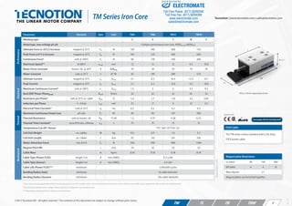
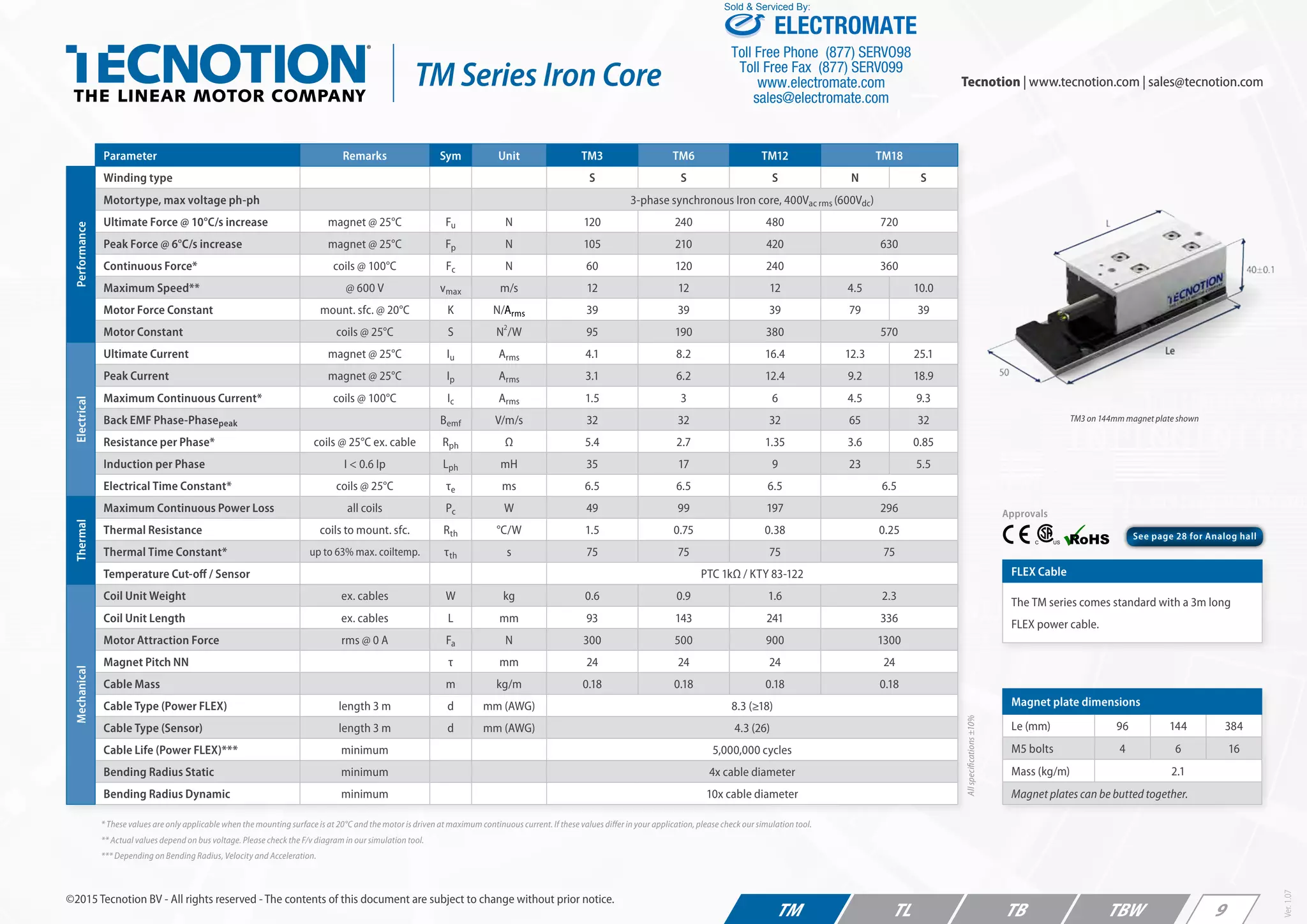

The document describes Tecnotion's TM series iron core motors. It provides specifications for the TM3, TM6, TM12, and TM18 models, including performance metrics like force, speed, current, and power. It lists dimensions and weights for the coil units and magnet plates. Mounting instructions and manuals can be downloaded from Tecnotion's website.


