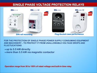
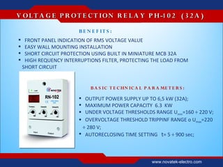
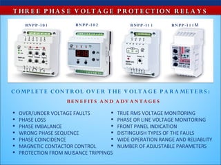
This document provides information on various automation, control, and protection devices from Novatek India. It describes single and three phase voltage protection relays, timers, temperature controllers, motor protection devices, and transformerless voltage stabilizers. The devices monitor and control key parameters like voltage, current, temperature, and protect equipment from faults. They feature easy installation, adjustable settings, communication interfaces, and software for configuration and data analysis.
The document describes a dual voltage regulator chip called the LDRxxyy. It has the following key specifications:
- It provides two independent voltage regulation channels, each able to supply up to 500mA or 1A respectively with low dropout voltages of 0.3V and 0.4V.
- It has very low quiescent current draw of only 50uA in off mode and 1.6mA maximum in on mode.
- Each output voltage channel can be independently enabled or shut down via logic control for low power applications like PDAs and data storage devices.
- The chip comes in PPAK and SPAK-7L packages and is suitable for applications from low noise
This document summarizes the key specifications of the LSF0108-Q100 8-bit bidirectional multi-voltage level translator. It supports translation between various voltage levels up to 100 MHz and is qualified for automotive applications from -40°C to +125°C. The device has 8 channels that allow for bidirectional translation between different voltage levels with no direction pin needed. It has applications in telecom infrastructure, industrial equipment, and automotive systems.
This document presents a mobile detector circuit that can detect incoming calls, texts, and video transmissions even when a mobile phone is set to silent mode. It consists of an antenna capacitor to capture RF signals, a voltage converter to convert the signals to voltages, a transistor amplifier, a timer circuit using an IC 555 chip to generate pulses, and a piezo buzzer to sound when a signal is detected. The circuit allows for detection of unauthorized mobile phone use in places like exam halls or confidential rooms, and can pick up signals from phones in silent mode. It has advantages of being low cost, easy to construct, and simple.
· Intrinsically Safe
· ANZEx, ATEX, IECEx, UL, cUL
· Input Voltage 16-30 VDC
· Reverse Polarity Protected
· Analog Voltage Output
· Short Circuit Protect
· Sync/Tx Input Line
· Various Sensing Ranges
· Wide Temperature Range
· Temperature Compensation
Model Number: RPS-409A-IS2 http://www.isweek.com/product/rps-409a-is2-ultrasonic-sensor-certified-safe-for-use-in-explosive-environments-rps-409a-is2_2197.html
This document is a project report on developing a "Mobile Bug" circuit to detect unauthorized mobile phone usage. It includes sections on the concept and purpose of detecting mobile signals, a description of the circuit components and design, and diagrams of the circuit. The circuit uses a capacitor to capture RF signals from mobile phones, an op-amp chip to convert the signals to voltages, and a timer chip and transistor to trigger an LED and buzzer on detection. The report provides details on the components, including the op-amp and timer chips, and concludes with a list of components used in the circuit.
The 555 timer IC is a versatile integrated circuit used in timer, pulse generation, and oscillator applications. It contains transistors, resistors, and diodes on a silicon chip. The 555 can be used in monostable, bistable, and astable modes to generate pulses or oscillations. It is commonly used in applications like blinking LEDs, timers, oscillators, and more due to its low cost, ease of use, and stability.
The document describes designing a frequency modulation (FM) signal using an ICNE566 voltage-controlled oscillator (VCO) chip and demodulating the signal using an ICLM565 phase-locked loop (PLL) chip. The modulation circuit uses the VCO with a resistor and capacitor to adjust the oscillation frequency based on an input voltage. For demodulation, the PLL chip extracts the original information from the modulated carrier wave. Hardware including the IC chips, resistors, capacitors, function generator, and power supply are used. The modulation and demodulation circuit diagrams and results are shown, verifying the design.
MOBILE BUG ; ACTIVE CELL PHONE DETECTOR USING CMOS & BIPOLAR TRANSISTORSShahrukh Javed
This document provides information about a project to build an active cell phone detector circuit. It includes a circuit diagram and descriptions of the major components used, including the CA3130 and NE555 integrated circuits. The circuit works by using a capacitor to detect radio frequency signals from nearby cell phones, converting this to a voltage that triggers a monostable multivibrator to activate an alarm. The detector is able to identify incoming/outgoing calls and video transmission from phones within 1-1.5 meters.
The 555 timer IC is a versatile integrated circuit used for timer and oscillator applications thanks to its low cost and stability. It was first released in 1971 and contains over 20 transistors, 2 diodes, and 15 resistors on a silicon chip. The 555 comes in several variants including the 556 with two 555 timers on one chip and the 558 with four timers. It can operate in monostable, astable, and bistable modes for applications like timers, oscillators, and switches. The output pulse width in monostable mode is determined by an RC circuit.
The UTC CXA1191 is a single-chip integrated circuit designed for FM/AM radio receivers in devices like cassette players and headphones. It integrates the key components needed for both FM and AM reception, including RF amplifiers, mixers, oscillators, IF amplifiers, detectors, and an audio power amplifier. The chip operates from a 2-8.5V supply and consumes under 10mA for FM reception and under 4mA for AM reception. It has features like automatic band switching between FM and AM, electronic volume control, and FM muting.
The document discusses the IC 555 timer integrated circuit. It describes how the IC 555 has been widely used since 1971, with over 1 billion units sold. It can be used in various operating modes like monostable, astable, and bistable. The document provides examples of using the IC 555 in monostable and astable modes for applications like turning on an LED periodically or building a clap-activated robot. Formulas for calculating timing are also given.
The document discusses the 555 timer integrated circuit, which is commonly used to generate clock pulses or time delays in electronic circuits. It describes the internal components of the 555 timer, including two comparators, a flip-flop, and three resistors that create a voltage divider. The 555 timer can operate in astable or monostable modes to produce oscillating or single output pulses using external resistors and capacitors. Formulas are provided to calculate the frequency, period, and duty cycle in astable mode and the time delay in monostable mode.
This document provides an addendum to the GSMV/GSMVCN GSM Cellular Communicator Installation and Setup Guide. It includes the following information:
1. Electrical specifications for the included AC transformer, including input power of 16.5VAC and positive/negative trigger voltage levels.
2. Wiring diagrams for connecting the GSMV zone input for positive and negative triggers, noting the required voltage levels for each.
3. Details on powering the communication module from the AC transformer for standard installations or from the control panel for ECP or ULC installations.
1. Operational amplifiers (op-amps) were first developed in 1947 using vacuum tubes and later improved with integrated circuit technology.
2. An op-amp is a high-gain differential amplifier used to perform mathematical operations such as summation, integration, and amplification of signals.
3. Key characteristics of an ideal op-amp include infinite input impedance, zero output impedance, infinite voltage gain, and zero noise. Real op-amps have high but not infinite values for these characteristics.
CONTROLLING HOME APPLIANCES USING REMOTE(1)Ambar Gupta
This document describes a home appliance control system that allows appliances to be controlled remotely using a TV remote. It consists of an IR receiver that receives signals from the remote and decodes the RC5 protocol. A microcontroller then determines which appliance is being controlled and sends signals to a relay driver IC to operate the appropriate relay and control appliances like lights and fans. The system provides remote control of appliances up to 10 meters away, allows easy control and monitoring, reduces human effort, and saves time and energy.
This document provides details on designing and using an in-circuit tester for line output transformers (LOPTs) in TVs and computer monitors. The tester uses a "ring testing" principle where a pulse is applied to the LOPT primary winding and the decay of the resulting ringing waveform is measured. A faster decay indicates increased losses likely due to a fault. The circuit generates pulses and compares ringing amplitude to light LEDs, with more LEDs indicating a healthier LOPT. It is battery powered, inexpensive, and allows testing components in the circuit without removal.
This document describes the design and operation of an inexpensive battery-powered tester for testing line output transformers (LOPTs) and other high frequency wound components. The tester uses a "ring testing" principle where a pulse is applied to the component being tested and the decay of the resulting ringing waveform is measured. Faster decay indicates increased losses likely due to a fault. The tester outputs a bar graph display showing the number of ringing cycles above a threshold, with more LEDs indicating a healthier component. Feedback from technicians found the tester capable of identifying at least 80% of LOPT faults in TVs and monitors.
1.Introduction
The 555 IC was designed in 1971 by Hans Camenzind under contract to SigNetics Corporation.
555 timer is a highly stable circuit used to generate time delays, or Oscillations.
A single 555 timer can provide time delay ranging from microseconds to hours.
It operates from a wide range of power supplies ranging from + 5 Volts to + 18 Volts supply voltage.
2.Pin Configuration
3.Working of Pin
4.555 Integral circuit
5.Operating modes of IC
6. Bistable Mode
In bistable (also called Schmitt trigger) mode, the 555 timer acts as a basic flip-flop.
The trigger and reset inputs (pins 2 and 4 respectively on a 555) are held high via pull-up resistors while the threshold input (pin 6) is simply floating.
Thus configured, pulling the trigger momentarily to ground acts as a 'set' and transitions the output pin (pin 3) to Vcc (high state).
Pulling the reset input to ground acts as a 'reset' and transitions the output pin to ground (low state). No timing capacitors
Pin 5 (control voltage) is connected to ground via a small-value capacitor (usually 0.01 to 0.1 μF). Pin 7 (discharge) is left floating
7.Monostable Mode
Pulse generator circuit which the period is calculated from RC network and connected to external of 555 timer
Stable when the output logic LOW (logic = 0)
When a pulse is trigger at pin 2 (normally negative trigger pulse), timer output will change to HIGH (+Vs) for a while and change to LOW (stable condition). The condition will continue LOW until pulse is trigger again.
The timing period is triggered (started) when trigger input (555 pin 2) is less than 1/3 Vs, this makes the output high (+Vs) and the capacitor C1 starts to charge through resistor R1. Once the time period has started further trigger pulses are ignored.
The threshold input (555 pin 6) monitors the voltage across C1 and when this reaches 2/3 Vs the time period over and the output becomes LOW,
At the same time discharge (555 pin 7) is connected to 0V, discharging the capacitor ready for the next trigger.
8.Astable Mode
Astable multivibrators are also known as Free-running Multivibrator.
Astable do not need trigger pulse for external to change the output.
The period for LOW and HIGH can be calculated based on resistor and capacitor value that connected at outside of timer.
9.Applications
Schmitt trigger
PPM
PWM
Linear Ramp generator
Precision Timing
Pulse Generation
Time Delay Generation
Sequential Timing
Used as a quad timer
10. Conclusion
Hence 555 IC timer can produce very accurate and stable time delays, from microseconds to hours. It can be used with supply voltage varying from 5 to 18 V. Timer can be used in monostable mode of operation or astable mode of operation. Its various applications include waveform generator, missing pulse detector, frequency divider, pulse width modulator, burglar alarm, FSK generator, ramp generator, pulse position modulator etc.
Tis s my innovative idea....Having the similar one which ill upload after lookiing at the response...hop it wil be iseful......COntact me in www.kylash.webs.com
This document summarizes the operation of an astable multivibrator circuit using a 555 timer integrated circuit. The circuit consists of two comparators, three 5k ohm resistors, and a 0.01uF capacitor. It generates a square wave output without needing an external trigger, with the high and low times determined by the resistor and capacitor values. The duty cycle of the output wave is calculated as the charge time divided by the total period. Key advantages are its simple operation, low external component count, and perfect square wave output, though the duty cycle is limited to above 50%.
An oscilloscope displays varying signal voltages over time. It plots voltage on the y-axis and time on the x-axis. Trigger controls allow stable displays of periodic or non-periodic signals. Accuracy refers to how close measurements are to the true value and can drift over time. Bandwidth is the range of frequencies over which accurate measurements can be made. Resolution is the smallest change that can alter the reading.
a project on automatic traffic control using IC 555jack990315
The document describes a student project to build an IC 555 and IC 4017 based traffic light circuit. It provides background on the history and purpose of traffic lights. It then details the components used in the circuit including IC 555 and IC 4017, and how they work together to simulate traffic light functionality by sequentially activating LED outputs to represent the changing lights. The document also covers potential issues with traffic and how temporary traffic control can help address them.
The 555 timer is a versatile integrated circuit that can be used to generate precise timing pulses or oscillations. It can operate from 3-15V and works in either monostable (one-shot) mode to produce a single pulse, or astable (multivibrator) mode to produce a continuous train of pulses. The duration of pulses in monostable mode or frequency in astable mode is determined by external resistor and capacitor values connected to the timer. Common applications include timers, flashing indicators, and pulse generation.
The presentation introduces a mobile phone detector that uses an IC, resistors, capacitors, a transistor, LED, battery, and breadboard. It detects active mobile phones within a working range using RF signals in the GHz range. The device has advantages of small size, lower power needs, and higher reliability. However, it also has limitations for high power or frequency use and silicon transistor sensitivity. It has applications in secure areas like embassies, exam halls, and military bases to prevent unauthorized phone use.
In this project an RF detector using tuned LC circuits is
formed for detecting signals in the GHz frequency band
used in mobile phones as the transmission frequency of
mobile phone ranges from 0.9 to 3 GHz.
The 555 timer is a versatile integrated circuit that can be used to generate accurate timing signals. It works by using internal comparators and a flip-flop to accurately time an external resistor-capacitor circuit. The 555 timer can be used in various configurations (monostable, bistable, astable) to generate pulses or oscillations for applications like timers, flashing lights, and tone generation. It is an inexpensive and robust chip contained in an 8-pin package that can drive loads directly from its output.
The 555 timer is an integrated circuit used to generate accurate time delays or oscillations. It contains two comparators, two transistors, and a flip-flop. The 555 timer is capable of producing accurate time delays or oscillations and is still widely used today due to its low price, ease of use, and good stability. It can be used in a variety of applications including precision timing, pulse generation, time delay generation, and sequential timing.
1. Selective coordination requires coordination between protective devices like circuit breakers from the utility source down to final subcircuits in order to isolate faults only to the protective device closest to the fault location.
2. Ground fault protection on feeders is required by NEC to provide an additional level of ground fault protection downstream from the service entrance with a minimum 6 cycle separation between service and feeder tripping bands to maintain selectivity.
3. While systems must be designed to withstand bolted faults, the majority of real-world faults will be arcing type faults which limit available fault current, making selective coordination more challenging but still achievable with proper protective device selection and settings.
This document provides information on various intelligent control, protection, and automation solutions from Novatek Electro, including single and three phase voltage protection relays, timers, motor protection devices, temperature controllers, and protocol converters. The relays and devices monitor voltage, current, temperature and other parameters and provide protection for electrical equipment and machinery from faults like over/under voltage, overloads, phase issues, and temperature abnormalities. They feature digital displays, adjustable settings, communication interfaces, and monitoring software.
early 1871 Belgian inventor Zénobe Gramme invented a generator powerful enough to produce power on a commercial scale for industry.[1]
In 1878, a hydroelectric power station was designed and built by William, Lord Armstrong at Cragside, England. It used water from lakes on his estate to power Siemens dynamos. The electricity supplied power to lights, heating, produced hot water, ran an elevator as well as labor-saving devices and farm buildings.[2]
In January 1882 the world's first public coal-fired power station, the Edison Electric Light Station, was built in London, a project of Thomas Edison organized by Edward Johnson. A Babcock & Wilcox boiler powered a 93 kW (125 horsepower) steam engine that drove a 27-tonne (27-long-ton) generator. This supplied electricity to premises in the area that could be reached through the culverts of the viaduct without digging up the road, which was the monopoly of the gas companies. The customers included the City Temple and the Old Bailey. Another important customer was the Telegraph Office of the General Post Office, but this could not be reached through the culverts. Johnson arranged for the supply cable to be run overhead, via Holborn Tavern and Newgate.[3]
In September 1882 in New York, the Pearl Street Station was established by Edison to provide electric lighting in the lower Manhattan Island area. The station ran until destroyed by fire in 1890. The station used reciprocating steam engines to turn direct-current generators. Because of the DC distribution, the service area was small, limited by voltage drop in the feeders. In 1886 George Westinghouse began building an alternating current system that used a transformer to step up voltage for long-distance transmission and then stepped it back down for indoor lighting, a more efficient and less expensive system which is similar to modern systems. The war of the currents eventually resolved in favor of AC distribution and utilization, although some DC systems persisted to the end of the 20th century. DC systems with a service radius of a mile (kilometer) or so were necessarily smaller, less efficient of fuel consumption, and more labor-intensive to operate than much larger central AC generating stations.early 1871 Belgian inventor Zénobe Gramme invented a generator powerful enough to produce power on a commercial scale for industry.[1]
In 1878, a hydroelectric power station was designed and built by William, Lord Armstrong at Cragside, England. It used water from lakes on his estate to power Siemens dynamos. The electricity supplied power to lights, heating, produced hot water, ran an elevator as well as labor-saving devices and farm buildings.[2]
In January 1882 the world's first public coal-fired power station, the Edison Electric Light Station, was built in London, a project of Thomas Edison organized by Edward Johnson. A Babcock & Wilcox boiler powered a 93 kW (125 horsepower) steam engine that drove a 27-tonne (27-long-ton) generator. This supplk
The document discusses uninterruptible power supply (UPS) systems. It describes various types of power problems that can occur and defines UPS as providing both power backup during outages and power conditioning to regulate voltage and frequency. It discusses online UPS systems in detail and their components like rectifiers, chargers, inverters and batteries. It also covers UPS configurations including single module, parallel and isolated redundant setups. Finally, it discusses best practices for mission critical power requirements and high reliability data center design.
Real time parameter estimation for power quality control and intelligent prot...EG TECHNOLOGIES
The document describes a method for real-time parameter estimation of power system impedance using signals from grid-connected power electronic converters. The proposed impedance estimation technique uses wavelets to analyze voltage and current transients from small disturbances imposed by power converters to determine the net impedance back to the power source. This allows for accurate impedance estimation within 5 milliseconds, providing the potential for fault detection within half a power cycle. The technique could enhance distributed generation operation during faults.
Analog & Digital Integrated Circuits - Material (Short Answers) Mathankumar S
This document contains two-mark questions and answers related to analog and digital integrated circuits. It includes definitions and explanations of terms like virtual short, differential amplifier, slew rate, characteristics of an ideal op-amp, common mode rejection ratio, average and peak detector, linear and non-linear applications of op-amps, precision diode, hysteresis, filters, power supply rejection ratio, and more. It also provides circuit diagrams for integrator, Schmitt trigger, astable multivibrator, full wave rectifier, and instrumentation amplifier.
This project detects power grid synchronization failures by monitoring voltage, frequency, and phase sequence. It uses a microcontroller to check if the voltage or frequency from a generator fall outside acceptable ranges when connecting to the grid. It also verifies correct phase sequence matching between the generator and grid. If any failures are detected, an alert is displayed on an LCD screen and a buzzer sounds to notify staff so corrective actions can be taken. This helps secure the power grid and prevent synchronization issues when integrating generator output.
Started to create milestones, we, Novatek Electro (India) Pvt. Ltd. marked our presence in the year 2009 and operate in the manufacturing/servicing of Microprocessor Based Devices as well as engineers of control since 5 years. Our quality services products have been always appreciated by our clients. Our spontaneous attitude and confident approach in offering an excellent range of Single Phase Voltage Monitoring Relays, Single Phase Voltage Monitoring Relays, Voltage Monitoring & Current Overload Relay, Powerful Voltage Monitoring Relays, Three Phase Voltage Monitoring Relays, Auto Phase Selector Switches, Time Delay Relays, Programmable Astro Timers, Sequential & Combination Timer, Numeric Motor Protection Devices has deepened our roots in the market. We, Novatek Electro (India) Pvt. Ltd. breathe with the aim of fully satisfying our clients with our high-quality products services. We are a unit of highly experienced professionals, all of them contributing at the best of their potentials to offer the highest degree of efficiency and client satisfaction.
This document describes a project to generate sinusoidal pulse width modulated (SPWM) signals using a microcontroller. It discusses SPWM signal generation by comparing a modulating sine wave with a triangular carrier wave. It also describes implementing SPWM signal generation algorithms using an 8051 microcontroller and simulating the output in Proteus. The document further discusses designing half bridge and full bridge inverters using an IR2110 driver circuit and optocouplers to interface with the microcontroller outputs. Assembly code is also presented for generating a single phase unipolar SPWM signal with the 8051 microcontroller.
The RC48C ground-fault ground-continuity monitor has two functions: (1) it measures residual current in electrical circuits to detect ground faults, and (2) it monitors the impedance of grounding conductors to detect issues. If a ground fault or impedance fault is detected, the monitor triggers an alarm relay that can disconnect power. The monitor is intended for use in mining applications to protect high-resistance grounded electrical systems.
This document describes a project to design a closed loop high static gain step-up DC-DC converter with magnetic coupling based on a modified SEPIC converter. The project aims to present a topology with low switch voltage and high efficiency for low input voltage and high output voltage applications. A hybrid PSOGSA algorithm is used for controller design. Hardware circuits are developed and tested, achieving an output voltage of 300V from an input of 15V with 92.2% efficiency using magnetic coupling, compared to 150V output without coupling.
This document provides details of the electrical installation for a school including:
- Specifications for the general switchboard, emergency switchboard, and distribution boards.
- Components included such as circuit breakers, transformers, surge protection devices.
- Cable sizes and types for wiring.
- Layout of the electrical rooms and distribution network.
- Notes on operation, protection coordination, and connection to monitoring systems.
The document discusses different types of electro-pneumatic and electro-hydraulic components including solenoid valves, relays, switches, and sensors. Solenoid valves use an electromagnet to actuate a pneumatic valve and control fluid flow. Relays are electromagnetically actuated switches that use a coil to switch contacts. Switches have normally open or closed contacts. Sensors convert physical values into electrical signals and can be contact or non-contact, with examples including limit switches, pressure sensors, and proximity sensors.
Automatic plant monitoring system have recently attracted tremendous interest due to the potential application in emerging technology. More importantly, this technique have improved and may be used to enhance the performance of existing techniques or to develop and design new techniques for the growth of plants . This project will shows the new source for watering the plants in the farms which is reducing the man power . This system will ensure that plants will be monitered without direct influence of men. For designing this system electronic devices like arduino ,sensors (pressure ,soil moisture) and servo , relay , display are used . we mainly introduced automatic watering of plants which shows much efficiency for watering plants compared to other techniques used which facilitates more effective multi-type harvesting the farms and clarifies a mechanism for realizing multi-functional practices in farms using electronic devices.
This document describes a plant monitoring system that uses various sensors to monitor the temperature, pressure, and humidity of a plant. It uses sensors like the BMP180 temperature/pressure sensor and soil moisture sensors connected to an Arduino board. The system has two operating modes - an automatic mode where it will water the plant if the soil is dry, and a manual mode to control servos and relays by hand. It aims to enhance plant growth by monitoring environmental conditions and responding accordingly, such as turning on a heater if the temperature is too low. Potential future improvements include adding a camera and connecting it to the internet via IoT.
The document provides the syllabus for an 8-week basic electrical, electronics, and computer training module. It covers topics like safety, hand tools, wires and cables, soldering, printed circuit boards, electrical measuring instruments, electrical accessories, basic electrical concepts, single and 3-phase systems, DC and AC motors, transformers, batteries, rectifiers, capacitors, transistors, integrated circuits, and introduces basic computer hardware, software applications like Windows, MS Word, and Excel. It also lists the skills trainees will gain in areas like identification, measurement, connection, and testing of electrical and electronic components.
The document discusses the purpose and performance specifications of an excitation system used to regulate the terminal voltage of an electrical machine. It describes the types of excitation systems as indirect or direct and covers topics like auto and manual controls, analog and digital control configurations, parameter settings, and limiters to prevent over and under excitation. The excitation system aims to maximize machine capability while maintaining stability under different operating conditions.
This document discusses testing and maintenance of power transformers. It begins with defining a transformer and its basic components like the iron core. It then discusses test requirements, the different types of transformer tests including routine tests, type tests and special tests. Routine tests are described in detail and include measuring voltage ratio, verifying vector group, measuring winding resistance, and impedance voltage testing. The document concludes with discussing regular maintenance activities for power transformers.
The document provides the syllabus for an 8-week basic electrical, electronics, and computer training module. It covers topics taught each week, including electrical safety, hand tools, circuits, electrical measuring instruments, single and 3-phase systems, motors, transformers, semiconductors, rectifiers, computers, MS Office applications, and networking basics. It also lists the skills trainees will gain in areas like electrical/electronic component connection, measurement, identification and testing.
This document describes the components and construction of a digital heart beat counter circuit. The circuit uses a piezoelectric sensor to detect heart beats which are then amplified and filtered. A 555 timer chip creates pulses from the filtered signal which are counted by a 4026 decade counter. The count is displayed on 7-segment LED displays. Key components include operational amplifiers, logic gates, voltage regulators, and LED displays. The circuit automatically counts heart beats over a 10 second interval and displays the result.
1. AUTOMATION, CONTROLS AND PROTECTION
INTETELLIGENT INDUSTRIAL ELECTRONICS
NOVATEK INDIA
МИКРОПРОЦЕССОРНЫЕ РЕЛЕЙНЫЕ УСТРОЙСТВА
www.novatek-electro.com
2. SINGLE PHASE VOLTAGE PROTECTION RELAYS
RN-1 1 1 RN-1 1 1 М RN-1 0 1 RN-1 0 1 М
DIN rail mounting Plug-Socket case performance
FOR THE PROTECTION OF SINGLE PHASE POWER SUPPLY CONSUMING EQUIPMENT
AND MACHINERY – TO PROTECT IT FROM UNALLOWABLE VOLTAGE DROPS AND
FLUCTUCATIONS
■ up to 3.5 kW directly
■ more than 3.5 kW via magnetic contactor
Operation range from 30 to 150% of rated voltage and built-in time relay
3. V O L T A G E P R O T E C T IO N R E L A Y P H-1 0 2 ( 3 2 A )
B E N E F IT S :
FRONT PANEL INDICATION OF RMS VOLTAGE VALUE
EASY WALL MOUNTING INSTALLATION
SHORT CIRCUIT PROTECTION USING BUILT IN MINIATURE MCB 32А
HIGH REQUENCY INTERRUPTIONS FILTER, PROTECTING THE LOAD FROM
SHORT CIRCUIT
B A S IC T E C HN IC A L P A R A ME T E R S :
OUTPUT POWER SUPPLY UP TO 6,5 kW (32A);
MAXIMUM POWER CAPACITY 6.3 KW
UNDER VOLTAGE THRESHOLDS RANGE Umin=160 ÷ 220 V;
OVERVOLTAGE THRESHOLD TRIPPINF RANGE о Umах=220
÷ 280 V;
AUTORECLOSING TIME SETTING t= 5 ÷ 900 sec;
www.novatek-electro.com
4. T HR E E P HA S E V O L T A G E P R O T E C T ION R E L A Y S
R N P P -3 0 1 R N P P -3 0 2 R N P P -3 1 1 R N P P -3 1 1 М
C O MP L E T E C O N T R O L O V E R T HE V O L T A G E P A R A ME T E R S :
B E N E F IT S A N D A D V A N T A G E S
OVER/UNDER VOLTAGE FAULTS TRUE RMS VOLTAGE MONITORING
PHASE LOSS PHASE OR LINE VOLTAGE MONITORING
PHASE IMBALANCE FRONT PANEL INDICATION
WRONG PHASE SEQUENCE DISTINGUISH TYPES OF THE FAULS
PHASE COINCIDENCE WIDE OPERATION RANGE AND RELIABLITY
MAGNETIC CONTACTOR CONTROL NUMBER OF ADJUSTABLE PARAMETERS
PROTECTION FROM NUISANCE TRIPPINGS
5. T W O C HA N N E L T IME D E L A Y R E L A Y S R E V S E R IE S
R E V -2 0 1 O P E R A T ION MO D E S :
2 INDEPENDENT CHANNELS
PARRALLEL CHANNELS OPERATION
COMBINATION OF CHANNELS
РЭВ -2 0 1
R E V -2 0 1 M MO D E S A N D B E N E F IT S :
TIME DELAY RELAY
IMPULSE RELAY
PERIODIC RELAY
CONTROL RELAY AND PRE-STARTING SIGNALIZATION
РЭВ -2 0 1 М
6. TIMERS AND HEALTHY PHASE SELECTORS
MU L T IF U N C T ION A L T IME R F O R ON E Y E A R
PROGRAMMABLE UPTO ONE YEAR;
PERPETUAL REAL TIME CLOCK WITH LOCATION PARAMETRS,
VOLTAGE PROTECTION RELAY;
PHOTO SENSORS
2 INDEPENDENT CHANELLS WITH 4 PROGRAMMS PER CHANNEL
FREE SOFTWARE WITH USB COMMUNICATION
LCD DISPLAY ON FRONT PANEL
R E V -3 0 2 E L E C T R O N IC HE A L T HY P HA S E S E L E C T OR
P E F -3 0 1
CONTROL OVER VOLTAGE ON EACH OF AVAILABLE LINES
SELECTS ANY OF THE LINES WITH REQUIRED PROPER
VOLTAGE PARAMETERS
POWER RESERVATION OF THE RESPONSIBLE CONSUMERS
COMPACT AUTOMATIC FALLBACK PANEL
OPERATION LOAD UP TO 3.5 KW DIRECTLY
WRONG VOLTAGE FAULT INDICATION
PROTECTION FROM INTERPHASE SWITCHING
OPERATION WITH GENERATORS
BUILT-IN AUTORECLOSING TIMER
P E F -3 0 1
7. O V E R L O A D R E L A Y R MT -1 0 1
O P E R A T IO N MO D E S :
DIGITAL AMPER-METER;
POWER CONSUMPTION LIMITING RELAY;
SELECTION OF THE PRIORITY POWER LOAD;
A DV A N T A G E S A N D
B E N E F IT S :
BUILT-IN CURRENT TRANSFORMER;
MAXIMAL CURRENT PROTECTION WITH
INDEPENDENT TIMING;
INDICATION OF CURRENT AND MAXIMAL VALUES;
POSSIBILITY TO DISABLE AUTORECLOSING.
T E C HN IC A L P A R A ME T E R S :
ADJUSTABLE CURRENT MONITORING RANGE: FROM 0 TO 100А;
MEASUREMENT ACCURACY: 1%
OVERCURRENT FAULT TRIPPING TIME DELAY 0 ÷ 300 SEC;
AUTORECLOSING TIME DELAY: 0 ÷ 900 SEC , ∞;
www.novatek-electro.com
8. A C MO T O R P R OT E C T ION D E V IC E S
U B Z -3 0 1 P E R F OR MS C OMP L E T E MO T O R
P R OT E C T ION IN T HE F OL L OW IN G C A S E S :
BAD QUALITY POWER SUPPLY VOLTAGE;
SYMMETRICAL OCERLOAD ON PHASE/LINE
CURRENTS DUE TO MECHANICAL MOTOR LOAD;
ASYMMETRICAL OVERLOAD;
PHASE CURRENTS ASYMMETRY WITHOUT
OVERLOAD,
PROTECTION ON STARTING/OPERATION CURRENT
DRY STROKE AND ABSENCE OF THE LOAD ON THE
MOTOR;
EARTH LEAKAGE PROTECTION WITH SUBSEQUENT
DISABLING OF AUTORECLOSING
A DV A N T A G E S :
EASY AND ACCURATE SETTING OF NOMINAL CURRENTS BEFORE THE MOTOR START
THERMAL OVERLOAD TRIPPING BASING THE CALCULATION OF THE DIFFERENTIAL HEATING
BALANCE EQUATION
INDICATION OF THE FAULTS ON A FRONT PANEL
PROTECTION AND OPERATION WITH THE MOTORS FROM 2.5 TO 315 kW
DATA TRANSMISSION TO THE UPPER LEVEL ON RS-485 PROTOCOL
www.novatek-electro.com
9. U N IV E R S A L A C MOT OR P R OT E C T IO N D E V IC E
U B Z -3 0 2 P R O V ID E S :
COMPLETE VOLTAGE/CURRENT PROTECTION
LONG LASTING START PROTECTION
LOCKED ROTOR AND DRY STROKING PROTECTION
TEMPERATURE CONTROL OVER THE MOTOR COILS
MOTOR COILS INSULATION LEVEL CONTROL
EARTH LEAKAGE AND FREQUENCY VARIATION
2 OU T P U T R E L A Y S P R OV ID E T HE P OS S IB IL IT Y F O R :
DELTA/STAR SWITCHING OPERATION
CASCADE MOTOR START (DELAYED STARTING OF MOTOR ONE BY ONE)
REMOTE TRIPPING THROUGH RELAY OUTPUT
B E N E F IT S A N D A D V A N T A G E S :
BUILT-IN CURRENT TRANSFORMERS AND PTs
OPERATION OF MOTOR AND DATA TRANSMISSION ON RS-485 AND MODBUS
OPERATION AND DATA TRANSMISSION ON RS-232 INTERFACE
COMPLETE WITH MONITORING, RECORDING AND ANALYSING SOFTWARE
www.novatek-electro.com
10. U N IV E R S A L A C MOT OR P R OT E C T IO N D E V IC E
S OF T W A R E S U P P OR T F O R R E A L T IME MON IT O R IN G , C O N V E N IE N T
P A R A ME T E R S E T T IN G S A N D S C A D A S Y S T E M IN T E G R A T IO N
11. U N IV E R S A L A C MOT OR P R OT E C T IO N D E V IC E
C O N F IG U R E A N D A D J U S T A L L T HE C O N T R OL L E D P A R A ME T E R S
U S IN G P C IN T E R F A C E
12. U N IV E R S A L A C MOT OR P R O T E C T IO N D E V IC E
R E A L T IME R E C OR D IN G O F D A T A A N D F A U L T HIS T OR Y ,
G R A P HIC A L A N A L Y S IS O F R E C O R D E D D A T A
13. U S B -F L A S H D R IV E R E C O R D E R R P M-1 6 -4 -3
B A S IC A P P L IC A T IO N A N D F U N C T ION S :
MEASUREMENT OF RMS AC VOLTAGE LEVEL;
MEASUREMENT OF RMS AC CURRENTS;
TEMPERATURE MEASUREMENT;
COLLECT INFORMATION FROM PRIMARY
TRANSDUCERS WITH STANDARD CURRENT OR
VOLTAGE OUTPUTS
RECORD OF THE MEASURED PARAMETERS AND
VALUES ONTO EXTERNAL USB-FLASH DRIVE
A L L OW S T O C ON N E C T A N D O P E R A T E U P T O 1 6 IN P U T ME A S U R E ME N T
C HA N N E L S :
4 CHANNELS FOR AC VOLTAGE 1-500V MEASUREMENT RANGE;
3 CHANNELS FOR CURRENT REGISTRATION 0-1000А USING EXTERNAL CURRENT TRANSFORMERS;
2 TEMPERATURE CHANNELS FROM -25 TO +100С BY MEANS OF NTC SENSORS;
2 CHANNELS WITH STANDARD OUTPUT SIGNAL (0/4-20 mА, 0-10V);
5 DIGITAL CHANNELS FOR THE SENSORS WITH DISCRETE (DIGITAL) OUTPUT.
R E C OR D E D IN F R OMA T ION IS P O S S IB L E T O V IE W U S IN G A N Y S T A N D A R D MS O F F IC E S O F T W A R E ,
A S W E L L A S W IT H T HE U S E OF T HE OR IG IN A L S OF T W A R E P R O V ID E D F OR V IE W IN G T HE G R A P HS
A N D W R IT T E N D A T A
www.novatek-electro.com
14. U S B -F L A S H D R IV E R E C O R D E R R P M-1 6 -4 -3
SOFTWARE INTERFACE FOR DATA ANALYSIS AND RECORDING HISTORY
15. T E MP E R A T U R E C ON T R O L L E R S MC K
S E R IE S
T E MP E R A T U R E C O N T R OL F O R :
• IN D U S T R IA L A IR -C O N D IT IO N IN G
• R E F R IG E R A T ION
• F R U IT -B A N A N A R IP P E N IN G R O O MS
• T E L E C O M MO B IL E B A S E S T A T IO N A N D
ATM
T E MP E R A T U R E C O N T R OL L E R S
• BUILT-IN VOLTAGE PROTECTION FROM ALL POSSIBLE VOLTAGE FAULTS
OPERATION WITH SINGLE AND THREE PHASE EQUIPMENT
www.novatek-electro.com
16. D IG IT A L T E MP E R A R U R E
D IG IT A L
C O N T R OL L E R
T E MP E R A T U R E R E L A Y T R -1 0 0
P R OV ID E S P R O T E C T ION
OF :
MOTORS
GENERATORS
DRY TYPE HIGH VOLTAGE TRANSFORMERS
TEMPERATURE MEASUREMENT ON 4 INPUT CHANNELS;
4 RELAY OUTPUT FOR ALARM, FAULT, COOLING, TRIPPING AND INDICATION OF THE
PARAMETERS
B E N E F IT S :
UNIVERSAL POWER INPUT POWER SUPPLY AC/DC FROM 24 TO 255V;
RS-485 INTERFACE AND MODBUS RTU PROTOCOLS OF DATA TRANSMISSION
www.novatek-electro.com
17. D IG IT A L T E MP E R A R U R E C O N T R O L L E R
SOFTWARE INTERFACE FOR REAL TIME MONITORING AND
PROGRAMMING
18. T R A N S F OR ME R L E S S V O L T A G E S T A B IL IZ E R S - L E G A T S E R IE S
N E W IN S IG HT T O
V O L T A G E S T A B IL IZ A T IO N
F A S T R E A C T ION T IME
1 0 0 % OU T P U T P OW E R
B E N E F IT S A N D A D V A N T A G E S :
GALVANICALLY INSULATED FROM CIRCUITS COMPACT AND LIGHT DUE TO THE ABSENSE
WITHSTAND 3 FOLD OVERLOAD OF POWER TRANSFORMERS INSIDE (HIGH
FREQUENCY MODULATION PRINCIPLE)
OUTPUT VOLTAGE SELECTION
WIDE OPERATION RANGE 100-280V, (FOR
1% OUTPUT VOLTAGE ACCURACY LEGAT-8 OPERATION RANGE 90-420V)
BUILT IN PROTECTION FROM ALL FAULTS 100% OUTPUT POWER THROUGHOUT ALL
FRONT PANEL INDICATION THE OPERATION VOLTAGE RANGE
www.novatek-electro.com