Downloaded 228 times


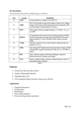
![Page | 11
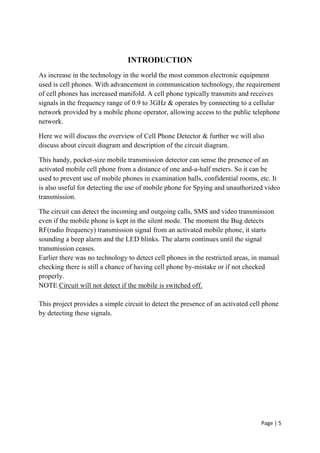
BLOCK DIAGRAM
Fig 3. Block diagram of circuit
There are four major blocks in the case of the cell phone detector. They are
○ Antenna ○ Current to voltage to converter
○ Monostable IC 555 ○ Output stage
Block Diagram and Working of Cell Phone Detector:
Ordinary LC (Coil-Capacitor) circuits are used to detect low frequency radiation in the AM
and FM bands. The tuned tank c1rcuit having 3 cm] and a variable capacitor retrieve the
signal from the carrier wave. But such LC circuits cannot detect high frequency waves near
the microwave region. Hence in the circuit a capacitor is used to detect RF from mobile
phone considering that a capacitor can store energy even from an outside source and oscillate
like LC circuit.](https://image.slidesharecdn.com/cpd-170131010509/85/MOBILE-BUG-ACTIVE-CELL-PHONE-DETECTOR-USING-CMOS-BIPOLAR-TRANSISTORS-11-320.jpg)
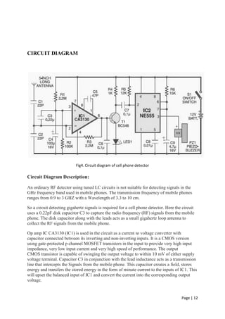

This document provides information about a project to build an active cell phone detector circuit. It includes a circuit diagram and descriptions of the major components used, including the CA3130 and NE555 integrated circuits. The circuit works by using a capacitor to detect radio frequency signals from nearby cell phones, converting this to a voltage that triggers a monostable multivibrator to activate an alarm. The detector is able to identify incoming/outgoing calls and video transmission from phones within 1-1.5 meters.


