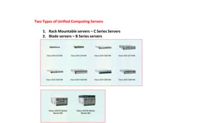
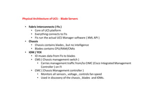
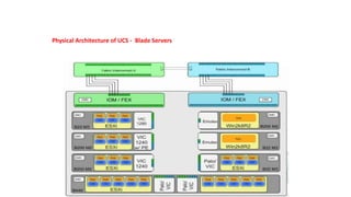
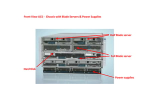
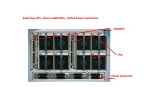
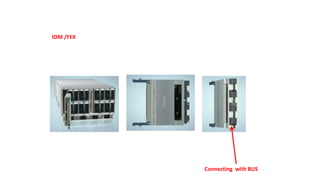
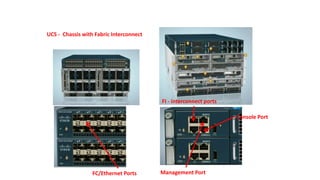
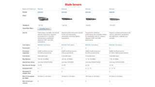
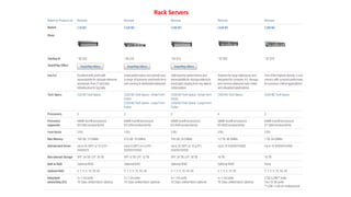
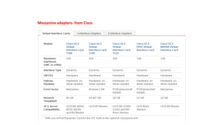
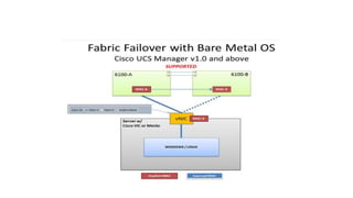
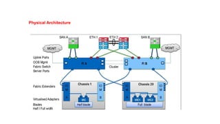
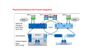
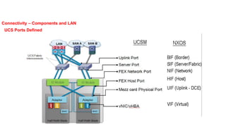
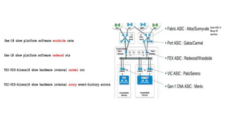
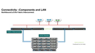
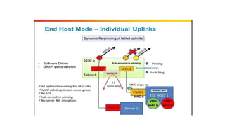
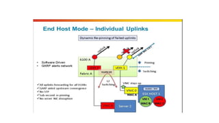
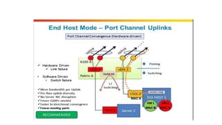
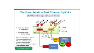
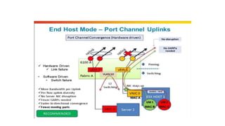
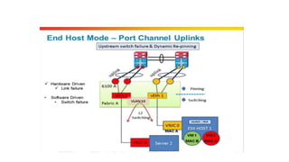
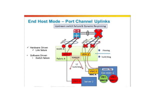
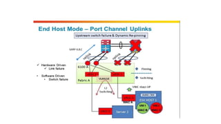
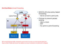
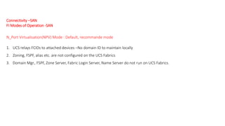
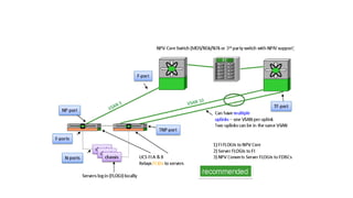
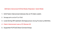
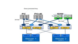
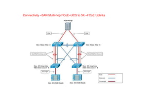
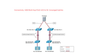
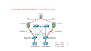
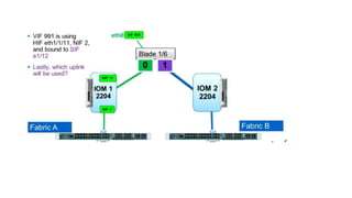
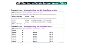
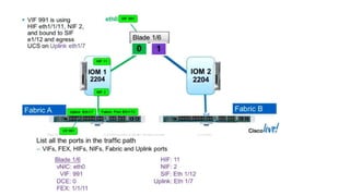
Two Types of Unified Computing Servers
1. Rack Mountable servers – C Series Servers
2. Blade servers – B Series servers
Physical Architecture of UCS - Blade Servers
• Fabric Interconnects ( FIs )
• Core of UCS platform
• Everything connects to FIs
• FIs run the actual UCS Manager software ( XML API )
• Chassis
• Chassis contains blades , but no intelligence
• Blades contains CPU/RAM/CNAs
• IOM / FEX
• IO muxes data from FIs to blades
• CMS ( Chassis management switch )
• Carries management traffic from/to CIMC (Cisco Integrated Management
Controller ) on FI
• CMC ( Chassis Management controller )
• Monitors all sensors , voltage , controls fan speed
• Used in discovery of the chassis , blades and IOMs.
Physical Architecture of UCS - Blade Servers
Front View UCS - Chassis with Blade Servers & Power Supplies
Half Blade server
Full Blade server
Power supplies
Hard Disk
Back View UCS - Chassis with IOMs , FANs & Power Connectors
IOM/FEX
FAN
Power Connector
IOM /FEX
Connecting with BUS
UCS - Chassis with Fabric Interconnect
Management PortFC/Ethernet Ports
Console Port
FI - interconnect ports
Half Blade Server
NIC/CAN Mezzanine Card
Hard Disk
Console
CPU Slots DIM Slots
Full Blade Server
Hard Disk
CPU Slots
DIM Slots
NIC/CAN Mezzanine Card
• FI – A connects with FI-B with a pair of cables – not for data , but only for
management purpose.
CMS CMS
• CMS are inbuilt in IOM/FEX. CMC on both the IOM/FEX are internally connected
to CMC of each and every blade.
• From each VIC/Emulex/CNA card ( mezzanine card ) on the blade a set of links
goes to IOM-A and other set of links goes to IOM-B. No. of Links depends upon
the card type.
• Uplinks from VIC to IOM are port channeled by default. The size of the port
channel depends upon the number of ports available on a particular card.
• Traffic from particular Application on VM/ESXi ( through vNIC) can select the
path towards the IOM-A or IOM-B with the concept of vPC Host Mode or MAC
Pinning ( based on source MAC address).
• In IOM/FEX ( 2208 XP ) there will be 8 ports facing the FI and 32 ports facing the
blades. Because we have max 8 half blades or 4 full blades in a chassis. On any
card we can have max 8 ports ( 4 towards IOM-A and 4 towards IOM-B ). So 8
blades x 4 ports on each blade = 32 Ports.
• It means that we do have oversubscription ratio of 8:32.
Selection of ports for traffic flow from IOM to Fabric Interconnect – Dynamic
Pinning
• If only one link exist than all the blades will send traffic towards that link shown
by red colour.
• If two link exist than all the odd number blades will send traffic towards link-1
shown by red colour and the even number blades will send traffic towards link-2
shown by green colour.
• If four link exist than the blades 1&5 will send traffic towards link-1 shown by
red colour and the blades 2&6 will send traffic towards link-2 shown by green
colour. Blades 3&7 will send traffic towards link-3 shown by blue colour and the
blades 4&8 will send traffic towards link-4 shown by yellow colour.
• If eight link exist than each blade will take as per the below diagram.
Selection of ports for traffic flow from IOM to Fabric Interconnect – Port Channel
• In case of port channel the load will be distributed using hash algorithm. No
mapping of particular port with particular blade. This is most recommended
method of deployment. Port channel can be of 2/4/8 ports.
Connecting IOM with Fabric Interconnect
Benefits Of UCS
1.Stateless computing: server does not have any MAC,WWN,NIC’s,UUID
address,Firmware and BIOS setting all abstracted from UCSM s/w running on FI.
2. Rapid Provisioning of Server: All identity installed from UCSM thus hundred of serevrs can be deploy
with in a days by creating templates.
3. Simplified troubleshooting: As stateless computing thus installing new server abstract all details of old
server from UCSM.
4.Virtualization readiness: Support all major hypervisor platform including VMware
ESXi, Microsoft hyper-V and citrix Xen Server.
5. Choice Of industry Form Factor: Both B-series and C-series server are designed using Intel Xeon CPU.
UCS hardware options
Fabric Interconnects
• Provides network connectivity (both LAN and SAN) and management of connected server.
• UCSM lies inside fabric interconnect can access through management interface.
• Core component of UCS Solution.
• Support all FCoE,FC and ethernet ports.
• FI are deployed in clustered pairs to provide high availability(Active-Active topology)
6100 series FI
1.UCS 6120XP: -20 10GE/FCoE ports in 1 RU.
-One expansion slots
2.UCS 6140XP: -40 10GE/FCoE ports in 2 RU.
-Two expansion slots
6200 series FI
1.UCS 6248UP: -32 fixed Unified ports w and 1 RU space.
-One expansion slots
-Support 20 blade chassis per FI
1.UCS 6296UP: -48 fixed Unified ports w and 1 RU space.
-Three expansion slots
-Support 20 blade chassis per FI
2204XP IOM/FEX
2208XP IOM/FEX
2104XP IOM/FEX
• Older Model
• 4 10 Gbps to FI
• 8 10 Gbps to Server
• 40 Gbps through put
• 2nd generation
• 4 10 Gbps fabric port to FI.
• 16 10 Gbps server facing ports with FCoE.
• 40 Gbps through put
• 2nd generation
• 8 10 Gbps fabric port to FI.
• 32 10 Gbps server facing ports with FCoE.
• 80 Gbps through put
Blade Servers
Rack Servers
Mezzanine adapters- from Cisco
Mezzanine adapters – from other Vendors
IOM/FEX Comparison with Mezzanine adapters (VIC)
Physical Architecture
Physical Architecture-with C-series Integration
LAN Connectivity
Connectivity – Components and LAN
UCS Ports Defined
Connectivity –Components and LAN
Northbound of the Fabric Interconnect
1. No spanning-tree protocol (STP); no blocked ports.—Simplified Upstream Connectivity.
2. Admin differentiates between server and network ports.
3. Using dynamic (or static) server to uplink pinning.
4. No MAC address learning except on the server ports; no unknown unicast flooding.
5. Fabric failover (FF) for Ethernet vNICs (not available in switch mode).
End-host mode (EHM): Default mode
Fabric interconnect
Fabric Interconnect –Ethernet EHM -Unicast Forwarding
GARP A,B,C
End Host Mode Unicast Forwarding
RPF:unicast/multicast traffic is forward to server only if it arrives on correct pinned uplink port.
Deja-vu-check: Packet with source mac-address to a server received on an uplink port is dropped.
1. Fabric Interconnects behave like regular ethernet switches.
2. STP configured for loop avoidance.
3. The uplinks ports are configured as forwarding or blocking as per the STP algorithm.
4. Not a default mode of operation.
Fabric Interconnect – Ethernet Switch Mode - Overview
Northbound of the Fabric Interconnect – Ethernet Switch
Mode - Overview
Designated Broadcast/Multicast Uplink Ports
• For any Broadcast/Multicast southbound traffic from N5K moving downward toward UCS Fabric Interconnects ,there
has to be a designated port on FI-A and FI-B.
• Suppose UCS FI-A chooses Po1 as its designated Broadcast/Multicast traffic receiver Port.
• Suppose UCS FI-B chooses Port 1/19 as its designated Broadcast/Multicast traffic receiver Port.
• Any Broadcast/Multicast traffic coming from N5K to UCS FI , but not on the defined as designated
Broadcast/Multicast ports will be dropped.
• Outgoing Broadcast/Multicast traffic is allowed on all the ports.
Blade server-1
   
Broadcast/Multicast Traffic
• Any incoming Broadcast/Multicast traffic is allowed only on designated Broadcast/Multicast ports only
and will be dropped on any other ports. This is to avoid loops as no STP is running .
• Outgoing Broadcast/Multicast traffic is allowed on all the ports.
Blade server-2
• Suppose UCS FI-B chooses Port 1/19 as its designated Broadcast/Multicast traffic receiver Port.
• vNIC2 ( having mac 00B1 ) is pinned to UCS FI-A uplink 1/17
• Any Broadcast/Multicast outgoing traffic coming from Server -1 vNIC 2 to UCS-F1-A will be blocked at all the ports on UCS FI-B except
1/19 .
• Any Broadcast/Multicast outgoing traffic coming from Server -1 vNIC 2 to UCS-F1-A and then again coming back to UCS FI-A via N5K1
to Po1 will also be dropped. This is called Deja-Vu Check (If I have seen that traffic(src-mac address) before ……drop it). This prevents
the loop.
Blade server-1

Blade server-2
1/191/17
OOB1

Po1
Key Points
1. Server vNIC pinned to an uplink port.
2. NO STP Protocol.
3. Maintains Mac table for server only not entire data center.
4. Prevent loops by preventing Uplink-to-uplink switching.
5. Upstream VPC/VSS optional(Best practice).
6. Server-to-Server traffic on the same vlan switched locally.
Recommended Topology for Upstream Connectivity
Always dual-attach each fabric interconnect to two Cisco Nexus 7000 Series Switches for high availability and redundancy whether
using vPC uplinks or individual uplinks without vPC.
Connectivity –SAN
Connectivity –SAN
FI Modes of Operation -SAN
N_Port Virtualisation(NPV) Mode : Default, recommande mode
1. UCS relays FCIDs to attached devices –No domain ID to maintain locally
2. Zoning, FSPF, alias etc. are not configured on the UCS Fabrics
3. Domain Mgr., FSPF, Zone Server, Fabric Login Server, Name Server do not run on UCS Fabrics.
SAN Fabric Interconnect FC/FCoE Mode of Operation –Switch Mode
1. UCS Fabric Interconnect behaves like an FC fabric switch.
2. Storage ports can be FC or FCoE.
3. Local Zoning OR Upstream Zoning(Upstream Zoning Provided by MDS/N5k).
4. Fabric Interconnect uses a FC Domain ID.
5. Supported FC/FCoE Direct Connect Arrays.
Direct connected Array
Connectivity –SAN Multi-hop FCoE–UCS to 5K –FCoE Uplinks
Connectivity –SAN Multi-hop FCoE–UCS to 5K -Converged Uplinks
Connectivity –SAN Multi-Hop FCoE–UCS to MDS –FCoE Uplinks
NETWORKERS HOME Cisco UCS PPT .

NETWORKERS HOME Cisco UCS PPT .

  • 2.
    Two Types ofUnified Computing Servers 1. Rack Mountable servers – C Series Servers 2. Blade servers – B Series servers
  • 3.
    Physical Architecture ofUCS - Blade Servers • Fabric Interconnects ( FIs ) • Core of UCS platform • Everything connects to FIs • FIs run the actual UCS Manager software ( XML API ) • Chassis • Chassis contains blades , but no intelligence • Blades contains CPU/RAM/CNAs • IOM / FEX • IO muxes data from FIs to blades • CMS ( Chassis management switch ) • Carries management traffic from/to CIMC (Cisco Integrated Management Controller ) on FI • CMC ( Chassis Management controller ) • Monitors all sensors , voltage , controls fan speed • Used in discovery of the chassis , blades and IOMs.
  • 4.
    Physical Architecture ofUCS - Blade Servers
  • 5.
    Front View UCS- Chassis with Blade Servers & Power Supplies Half Blade server Full Blade server Power supplies Hard Disk
  • 6.
    Back View UCS- Chassis with IOMs , FANs & Power Connectors IOM/FEX FAN Power Connector
  • 7.
  • 8.
    UCS - Chassiswith Fabric Interconnect Management PortFC/Ethernet Ports Console Port FI - interconnect ports
  • 9.
    Half Blade Server NIC/CANMezzanine Card Hard Disk Console CPU Slots DIM Slots
  • 10.
    Full Blade Server HardDisk CPU Slots DIM Slots NIC/CAN Mezzanine Card
  • 11.
    • FI –A connects with FI-B with a pair of cables – not for data , but only for management purpose. CMS CMS • CMS are inbuilt in IOM/FEX. CMC on both the IOM/FEX are internally connected to CMC of each and every blade.
  • 12.
    • From eachVIC/Emulex/CNA card ( mezzanine card ) on the blade a set of links goes to IOM-A and other set of links goes to IOM-B. No. of Links depends upon the card type.
  • 13.
    • Uplinks fromVIC to IOM are port channeled by default. The size of the port channel depends upon the number of ports available on a particular card. • Traffic from particular Application on VM/ESXi ( through vNIC) can select the path towards the IOM-A or IOM-B with the concept of vPC Host Mode or MAC Pinning ( based on source MAC address).
  • 14.
    • In IOM/FEX( 2208 XP ) there will be 8 ports facing the FI and 32 ports facing the blades. Because we have max 8 half blades or 4 full blades in a chassis. On any card we can have max 8 ports ( 4 towards IOM-A and 4 towards IOM-B ). So 8 blades x 4 ports on each blade = 32 Ports. • It means that we do have oversubscription ratio of 8:32.
  • 15.
    Selection of portsfor traffic flow from IOM to Fabric Interconnect – Dynamic Pinning • If only one link exist than all the blades will send traffic towards that link shown by red colour.
  • 16.
    • If twolink exist than all the odd number blades will send traffic towards link-1 shown by red colour and the even number blades will send traffic towards link-2 shown by green colour.
  • 17.
    • If fourlink exist than the blades 1&5 will send traffic towards link-1 shown by red colour and the blades 2&6 will send traffic towards link-2 shown by green colour. Blades 3&7 will send traffic towards link-3 shown by blue colour and the blades 4&8 will send traffic towards link-4 shown by yellow colour.
  • 18.
    • If eightlink exist than each blade will take as per the below diagram.
  • 19.
    Selection of portsfor traffic flow from IOM to Fabric Interconnect – Port Channel • In case of port channel the load will be distributed using hash algorithm. No mapping of particular port with particular blade. This is most recommended method of deployment. Port channel can be of 2/4/8 ports.
  • 20.
    Connecting IOM withFabric Interconnect
  • 21.
    Benefits Of UCS 1.Statelesscomputing: server does not have any MAC,WWN,NIC’s,UUID address,Firmware and BIOS setting all abstracted from UCSM s/w running on FI. 2. Rapid Provisioning of Server: All identity installed from UCSM thus hundred of serevrs can be deploy with in a days by creating templates. 3. Simplified troubleshooting: As stateless computing thus installing new server abstract all details of old server from UCSM. 4.Virtualization readiness: Support all major hypervisor platform including VMware ESXi, Microsoft hyper-V and citrix Xen Server. 5. Choice Of industry Form Factor: Both B-series and C-series server are designed using Intel Xeon CPU.
  • 22.
    UCS hardware options FabricInterconnects • Provides network connectivity (both LAN and SAN) and management of connected server. • UCSM lies inside fabric interconnect can access through management interface. • Core component of UCS Solution. • Support all FCoE,FC and ethernet ports. • FI are deployed in clustered pairs to provide high availability(Active-Active topology) 6100 series FI 1.UCS 6120XP: -20 10GE/FCoE ports in 1 RU. -One expansion slots 2.UCS 6140XP: -40 10GE/FCoE ports in 2 RU. -Two expansion slots
  • 23.
    6200 series FI 1.UCS6248UP: -32 fixed Unified ports w and 1 RU space. -One expansion slots -Support 20 blade chassis per FI 1.UCS 6296UP: -48 fixed Unified ports w and 1 RU space. -Three expansion slots -Support 20 blade chassis per FI
  • 24.
    2204XP IOM/FEX 2208XP IOM/FEX 2104XPIOM/FEX • Older Model • 4 10 Gbps to FI • 8 10 Gbps to Server • 40 Gbps through put • 2nd generation • 4 10 Gbps fabric port to FI. • 16 10 Gbps server facing ports with FCoE. • 40 Gbps through put • 2nd generation • 8 10 Gbps fabric port to FI. • 32 10 Gbps server facing ports with FCoE. • 80 Gbps through put
  • 25.
  • 26.
  • 27.
  • 30.
    Mezzanine adapters –from other Vendors
  • 31.
    IOM/FEX Comparison withMezzanine adapters (VIC)
  • 32.
  • 33.
  • 34.
  • 35.
    Connectivity – Componentsand LAN UCS Ports Defined
  • 37.
    Connectivity –Components andLAN Northbound of the Fabric Interconnect
  • 38.
    1. No spanning-treeprotocol (STP); no blocked ports.—Simplified Upstream Connectivity. 2. Admin differentiates between server and network ports. 3. Using dynamic (or static) server to uplink pinning. 4. No MAC address learning except on the server ports; no unknown unicast flooding. 5. Fabric failover (FF) for Ethernet vNICs (not available in switch mode). End-host mode (EHM): Default mode Fabric interconnect
  • 40.
    Fabric Interconnect –EthernetEHM -Unicast Forwarding
  • 48.
  • 52.
    End Host ModeUnicast Forwarding RPF:unicast/multicast traffic is forward to server only if it arrives on correct pinned uplink port. Deja-vu-check: Packet with source mac-address to a server received on an uplink port is dropped.
  • 53.
    1. Fabric Interconnectsbehave like regular ethernet switches. 2. STP configured for loop avoidance. 3. The uplinks ports are configured as forwarding or blocking as per the STP algorithm. 4. Not a default mode of operation. Fabric Interconnect – Ethernet Switch Mode - Overview
  • 54.
    Northbound of theFabric Interconnect – Ethernet Switch Mode - Overview
  • 55.
    Designated Broadcast/Multicast UplinkPorts • For any Broadcast/Multicast southbound traffic from N5K moving downward toward UCS Fabric Interconnects ,there has to be a designated port on FI-A and FI-B. • Suppose UCS FI-A chooses Po1 as its designated Broadcast/Multicast traffic receiver Port. • Suppose UCS FI-B chooses Port 1/19 as its designated Broadcast/Multicast traffic receiver Port. • Any Broadcast/Multicast traffic coming from N5K to UCS FI , but not on the defined as designated Broadcast/Multicast ports will be dropped. • Outgoing Broadcast/Multicast traffic is allowed on all the ports.
  • 56.
    Blade server-1    Broadcast/Multicast Traffic • Any incoming Broadcast/Multicast traffic is allowed only on designated Broadcast/Multicast ports only and will be dropped on any other ports. This is to avoid loops as no STP is running . • Outgoing Broadcast/Multicast traffic is allowed on all the ports. Blade server-2
  • 57.
    • Suppose UCSFI-B chooses Port 1/19 as its designated Broadcast/Multicast traffic receiver Port. • vNIC2 ( having mac 00B1 ) is pinned to UCS FI-A uplink 1/17 • Any Broadcast/Multicast outgoing traffic coming from Server -1 vNIC 2 to UCS-F1-A will be blocked at all the ports on UCS FI-B except 1/19 . • Any Broadcast/Multicast outgoing traffic coming from Server -1 vNIC 2 to UCS-F1-A and then again coming back to UCS FI-A via N5K1 to Po1 will also be dropped. This is called Deja-Vu Check (If I have seen that traffic(src-mac address) before ……drop it). This prevents the loop.
  • 58.
  • 59.
    Key Points 1. ServervNIC pinned to an uplink port. 2. NO STP Protocol. 3. Maintains Mac table for server only not entire data center. 4. Prevent loops by preventing Uplink-to-uplink switching. 5. Upstream VPC/VSS optional(Best practice). 6. Server-to-Server traffic on the same vlan switched locally.
  • 60.
    Recommended Topology forUpstream Connectivity Always dual-attach each fabric interconnect to two Cisco Nexus 7000 Series Switches for high availability and redundancy whether using vPC uplinks or individual uplinks without vPC.
  • 61.
  • 62.
    Connectivity –SAN FI Modesof Operation -SAN N_Port Virtualisation(NPV) Mode : Default, recommande mode 1. UCS relays FCIDs to attached devices –No domain ID to maintain locally 2. Zoning, FSPF, alias etc. are not configured on the UCS Fabrics 3. Domain Mgr., FSPF, Zone Server, Fabric Login Server, Name Server do not run on UCS Fabrics.
  • 64.
    SAN Fabric InterconnectFC/FCoE Mode of Operation –Switch Mode 1. UCS Fabric Interconnect behaves like an FC fabric switch. 2. Storage ports can be FC or FCoE. 3. Local Zoning OR Upstream Zoning(Upstream Zoning Provided by MDS/N5k). 4. Fabric Interconnect uses a FC Domain ID. 5. Supported FC/FCoE Direct Connect Arrays.
  • 65.
  • 66.
    Connectivity –SAN Multi-hopFCoE–UCS to 5K –FCoE Uplinks
  • 67.
    Connectivity –SAN Multi-hopFCoE–UCS to 5K -Converged Uplinks
  • 68.
    Connectivity –SAN Multi-HopFCoE–UCS to MDS –FCoE Uplinks