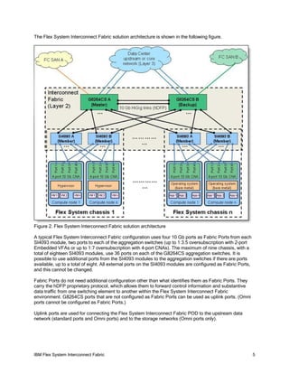
The IBM Flex System Interconnect Fabric provides a scalable network fabric for connecting compute nodes and storage within a Flex System POD using a single IP management approach. Key components include the SI4093 System Interconnect module for connecting nodes within a chassis and G8264CS aggregation switches. The fabric reduces latency and simplifies management by representing the POD as a single network element to upstream networks while providing a loop-free Layer 2 network internally.
IBM Flex System Interconnect Fabric Simplifies Networking
1. IBM Flex System Interconnect Fabric 1
®
IBM Flex System Interconnect Fabric
IBM Redbooks Solution Guide
IBM® Flex System® Interconnect Fabric offers a solid foundation of compute, network, storage, and
software resources in a Flex System point of delivery (POD). The entire POD integrates a seamless
network fabric for compute node and storage under single IP management, and it attaches to the
upstream data center network as a loop-free Layer 2 network fabric with a single Ethernet uplink
connection or aggregation group to each layer 2 network, as shown in the following figure. The POD
requires only network provisioning for uplink connections to a data center network, downlink connections
to compute nodes, and storage connections to storage nodes.
Figure 1. IBM Flex System Interconnect Fabric
Did you know?
Flex System Interconnect Fabric reduces communication latency and improves application response time
with support for local switching within the chassis, and it reduces networking management complexity
without compromising performance by lowering the number of devices that must be managed by 95%
(managing one device instead of 20).
Flex System Interconnect Fabric simplifies POD integration into an upstream network by transparently
interconnecting hosts to a data center network and representing the POD as a large compute element
isolating the POD's internal connectivity topology and protocols from the rest of the network.
2. IBM Flex System Interconnect Fabric 2
Business value
The Flex System Interconnect Fabric solution offers the following benefits:
Network simplification
Provisions a seamless network fabric for compute node and storage connectivity in the datao
center.
Offers a loop-free network fabric without STP complexity for fast network convergence.o
Minimizes network latency by local Layer 2 switching at every interconnect component ando
minimizes loss of data during network failover within the fabric.
Converges Ethernet for lossless storage traffic.o
Integrates FCF to provide end-to-end FCoE storage functionality within the POD without needingo
an expensive Fibre Channel switch.
Supports single fabric mode topology and dual fabric mode topology.o
Management simplification
Offers high availability with master and backup Top of Rack (TOR) switches in the fabric ando
hitless upgrade with no downtime for services.
Minimizes managed network elements with single point of management of the entire fabric at theo
master TOR switch.
Establishes a clear administrative boundary in data center by pushing traditional networkingo
configuration outside of the POD.
Integrates physical and virtual infrastructure management for compute, network, storage, ando
software elements.
Storage integration
Simplifies integration of storage and storage virtualization with IBM Flex System V7000 Storageo
Node.
Provides access to an external SAN storage infrastructure, such as IBM Storwize® V7000.o
Scalable POD design
Enables the size of the POD to grow without adding management complexity.o
Adds chassis resources up to the maximum configuration under the single IP management of theo
POD.
3. IBM Flex System Interconnect Fabric 3
Solution overview
The Flex System Interconnect Fabric solution has the following key elements:
Hardware elements
IBM RackSwitch™ G8264CS (10/40 GbE, 4/8 Gb FC uplink) as Aggregation
Flex System Fabric SI4093 System Interconnect Module (10 GbE to compute node) as Access
Embedded VFA, CN4054, or CN4058 adapters
Flex System V7000 Storage Node or Storwize V7000
Software elements
Single IP managed multi-rack cluster (hDFP)
Automated rolling (staggered) upgrades of individual switches
Per-server link redundancy (LAG or active/passive teaming)
Dynamic bandwidth within and out of the POD
Multi-rack Flex System Interconnect mode
Integration of UFP and IBM VMready®
Management elements
IBM System Networking Switch Center management application (fabric management)
Flex System Manager configuration patterns (compute node NIC configuration)
Flex System Interconnect Fabric supports the following networking software features:
Single IP managed cluster
1024 VLANs
Layer 2 loop-free solution with upstream data center core
FCoE and native Fibre Channel support
Eight unicast traffic classes and four multicast traffic classes with configurable bandwidth
Priority flow control for maximum of two priorities
UFP virtual port support (four per 10 Gb physical port)
VMready
VMready/FCoE interoperability with UFP
Tunneled VLAN domain (Q-in-Q) for multi-tenant customer VLAN isolation
IGMPv2 Snooping for multicast optimization
256 access lists and 128 VLAN maps for security and rate limiting policing
Static/LACP portchannel
L2 Failover (Manual Monitor - MMON)
Hotlinks
VLAN-based load distribution in hotlinks (for active/active connectivity with non-vPC uplink)
Industry-standard command-line interface (isCLI)
SNMP
IPv6 support for management
Staggered upgrade
HiGig trunk
Local preference for unicast traffic
Port mirroring
4. IBM Flex System Interconnect Fabric 4
Solution architecture
The SI4093, an embedded module, has 42 10GBASE-KR ports that connect to the compute nodes in the
Flex System chassis through the midplane; there are three 10 Gb ports that connect to each of the 14
slots in the chassis.
The G8264CS has 12 Omni ports, which can be configured to operate either as 4/8 Gb Fibre Channel
ports or as 10 Gb Ethernet ports. It also has an internal hardware module with a dedicated ASIC, which
provides the FC gateway functionality (FCF and NPV).
Both the SI4093 and G8264CS have PHY interfaces for SFP+ transceivers and QSFP+ transceivers that
can run either as a single 40 Gb port or as a set of four 10 Gb ports using a breakout cable. The
interconnection between the SI4093 modules and the G8264CS aggregation switches is configured to run
over standard 10 Gb connections. Similar connections are used between the pair of G8264CS
aggregation switches, although it is possible to use 40 Gb links here. A Broadcom proprietary protocol,
hDFP, is used over these links, which are referred to in the diagrams in this solution guide as HiGig links.
This protocol carries proprietary control information and the content of the network traffic, and it enables
the multiple switching processors in the different switches to operate as though they are part of a single
switch.
In the Flex System Interconnect Fabric, one of the G8264CS aggregation switches is the master and the
other is a backup for purposes of managing the environment. If the master switch fails, the backup
G8264CS aggregation switch takes on this task.
The links between switching elements in an Flex System Interconnect Fabric configuration are known as
Fabric Ports. Fabric Ports must be explicitly configured on both sides, and assigned to a reserved VLAN.
If two or more Fabric Ports are connected between the same two devices, then all of them are used as the
aggregated link that forms automatically.
5. IBM Flex System Interconnect Fabric 5
The Flex System Interconnect Fabric solution architecture is shown in the following figure.
Figure 2. Flex System Interconnect Fabric solution architecture
A typical Flex System Interconnect Fabric configuration uses four 10 Gb ports as Fabric Ports from each
SI4093 module, two ports to each of the aggregation switches (up to 1:3.5 oversubscription with 2-port
Embedded VFAs or up to 1:7 oversubscription with 4-port CNAs). The maximum of nine chassis, with a
total of eighteen SI4093 modules, use 36 ports on each of the G8264CS aggregation switches. It is
possible to use additional ports from the SI4093 modules to the aggregation switches if there are ports
available, up to a total of eight. All external ports on the SI4093 modules are configured as Fabric Ports,
and this cannot be changed.
Fabric Ports do not need additional configuration other than what identifies them as Fabric Ports. They
carry the hDFP proprietary protocol, which allows them to forward control information and substantive
data traffic from one switching element to another within the Flex System Interconnect Fabric
environment. G8264CS ports that are not configured as Fabric Ports can be used as uplink ports. (Omni
ports cannot be configured as Fabric Ports.)
Uplink ports are used for connecting the Flex System Interconnect Fabric POD to the upstream data
network (standard ports and Omni ports) and to the storage networks (Omni ports only).
6. IBM Flex System Interconnect Fabric 6
Flex System Interconnect Fabric is formed on its own by establishing HiGig links using the configured
Fabric Ports. All HiGig links are active, and they carry network traffic. The actual traffic flow path between
the different members in the fabric is established when a member joins the fabric or other topology
change occurs. The data path should be balanced as well as possible.
Usage scenarios
The Flex System Interconnect Fabric can be VLAN-aware or VLAN-agnostic depending on specific client
requirements.
In VLAN-aware mode (shown in the following figure), client VLAN isolation is extended to the fabric by
filtering and forwarding VLAN tagged frames that are based on the client VLAN tag, and client VLANs
from the upstream network are configured within the Flex System Interconnect Fabric and on virtual
switches (vSwitches) in hypervisors.
Figure 3. VLAN-aware Flex System Interconnect Fabric
7. IBM Flex System Interconnect Fabric 7
In VLAN-agnostic mode (shown in the following figure), the Flex System Interconnect Fabric transparently
forwards VLAN tagged frames without filtering on the client VLAN tag, providing an end host view to the
upstream network, where client VLANs are configured on vSwitches only. This is achieved by the use of a
Q-in-Q type operation to hide user VLANs from the switch fabric in the POD so that the Flex System
Interconnect Fabric acts as more of a port aggregator and is user VLAN-independent.
The VLAN-agnostic mode of the Flex System Interconnect Fabric can be implemented through the
tagpvid-ingress feature or UFP vPort tunnel mode. If no storage access is required for the compute nodes
in the POD, then the tagpvid-ingress mode is the simplest way to configure the fabric. However, if you
want to use FCoE storage, you cannot use the tagpvid-ingress feature and must switch to UFP tunnel
mode.
Figure 4. VLAN-agnostic Flex System Interconnect Fabric
All VMs that are connected to the same client VLAN can communicate with each other within the POD
and with other endpoints that are attached to this VLAN in the upstream network. VMs and endpoints that
are connected to different VLANs cannot communicate with each other in the Layer 2 network.
vSwitches are connected to Flex System Interconnect Fabric through a teamed NIC interface that is
configured on the compute node. The compute node’s CNA NIC ports (either physical (pNIC) or virtual
(UFP vPort) ports) are configured in a load-balancing pair (static or LACP aggregation) using the
hypervisor’s teaming/bonding feature. Respective compute node-facing ports on the SI4093 modules are
also configured for static or dynamic aggregation, and VLAN tagging (802.1Q) is enabled on the
aggregated link.
8. IBM Flex System Interconnect Fabric 8
If the upstream network supports distributed (also called virtual) link aggregation, this type of aggregation
can be used to connect Flex System Interconnect Fabric to the core. Flex System Interconnect Fabric
sees the upstream network as one logical switch, and the upstream network sees Flex System
Interconnect Fabric as one logical switch. A single aggregated port channel (static or dynamic) is
configured between these two logical switches using all connected uplinks, and all these links in the
aggregation carry traffic from all client VLANs.
If virtual link aggregation is not supported on the upstream network switches (that is, the upstream
network operates in a standard STP domain), then Hot Link interfaces are used. Flex System
Interconnect Fabric sees the upstream network as two separate switches, and the upstream network sees
Flex System Interconnect Fabric as one logical switch.
This logical switch is connected to the upstream switches using two aggregated port channels (static or
dynamic):
One port channel is configured between the first upstream switch and the Flex System Interconnect
Fabric logical switch.
Another port channel is configured between the second upstream switch and the Flex System
Interconnect Fabric logical switch.
One port channel is designated as the master hot link, and the second port channel is configured as the
backup hot link. The master port channel carries traffic from all client VLANs, and the backup port channel
is in the blocking state. If there is a master port channel failure, the backup port channel becomes active
and all traffic flows through it. The downside of this approach is that only half of the available uplink
bandwidth is used. Flex System Interconnect Fabric supports VLAN load distribution over Hot Links to
maximize bandwidth usage, and both hot links are masters and backups for different VLANs at the same
time.
Integration
The Flex System Interconnect Fabric converged network design enables shared access to the full
capabilities of the FCoE-based V7000 Storage Node and Storwize V7000 storage systems while
simultaneously providing connectivity to the client’s enterprise FC SAN storage environment.
Flex System Interconnect Fabric introduces a new storage fabric capability that is called Hybrid Fabric, in
which there are two types of SANs, internal and external, on separate SAN fabrics. The internal SAN is
used for the POD-wide V7000 Storage Node or Storwize V7000 connectivity in Full Fabric mode, and the
external SAN is used for the data center-wide storage connectivity in NPV Gateway mode. Both internal
and external SANs are dual-fabric SANs, and the total number of fabrics in the hybrid storage
configuration is four.
Hybrid mode requires dual initiators per compute node connection to each SI4093 module so that each
initiator can discover one FC fabric. Each initiator can communicate only with one FCF VLAN and FC
fabric. The 4-port and 8-port CNAs offer the required number of ports to support dual switch path storage
access. Dual-port CNAs (such as embedded VFA LOM) can also be used for storage connectivity, but
only one type of dual-fabric SAN can be used, either internal or external but not both. Each HBA port on
the CNA that is installed in the compute node is connected to the dedicated fabric. Path redundancy is
provided with the usage of MPIO software that is installed on the compute node (in the bare-metal
operating system or in the hypervisor).
9. IBM Flex System Interconnect Fabric 9
The hybrid storage configuration, which uses both internal IBM Flex System V7000 Storage Node and the
client's external storage, is shown in the following figure.
Figure 5. Flex System Interconnect Fabric storage integration
The compute node’s HBA ports 1 and 2 are used to connect to the internal storage in the Full Fabric
mode, and HBA ports 3 and 4 provide connectivity to the external FC SAN storage in the NPV mode.
Supported platforms
Flex System Interconnect Fabric is supported by the following network devices:
IBM RackSwitch G8264CS
IBM Flex System Fabric SI4093 System Interconnect Module
Note: Two G8264CS switches and from two to 18 SI4093 modules are supported in a POD. G8264CS
switches and SI4093 modules in a POD run a special Flex System Interconnect Fabric software image of
IBM Networking OS V7.8 or later.
10. IBM Flex System Interconnect Fabric 10
The following adapters are supported:
IBM Flex System Embedded Virtual Fabric LOM
IBM Flex System CN4054/CN4054R 10Gb Virtual Fabric Adapter
IBM Flex System CN4058 10Gb Converged Adapter
Ordering information
The following table shows example bill of materials (BOM) for a 3-chassis Flex System Interconnect
Fabric POD consisting of the following items:
Six SI4093 modules
Two G8264CS switches with the required SFP+ DAC cables
Required rack and PDU infrastructure
Optional IBM System Networking Switch Center management application
Note: Up to 42 half-wide or 84 high-density compute nodes can be used in this example, but they are not
included in the table.
Table 1. Ordering part numbers
Part number Description Quantity
Rack and PDU infrastructure
93604PX IBM 42U 1200mm Deep Dynamic Rack 1
46M4143 IBM 0U 12 C19/12 C13 32A 3 Phase PDU 2
25R5559 1U Quick Install Filler Panel Kit 2
Top of Rack switches
7309DRX IBM System Networking RackSwitch G8264CS (Rear-to-Front) 2
90Y9430 3m IBM Passive DAC SFP+ Cable 16
90Y9427 1m IBM Passive DAC SFP+ Cable 10
Flex System Enterprise Chassis with SI4093 modules
8721A1G IBM Flex System Enterprise Chassis with 2x2500W PSU 3
43W9049 IBM Flex System Enterprise Chassis 2500W Power Module 12
95Y3313 IBM Flex System Fabric SI4093 System Interconnect Module 6
68Y7030 IBM Flex System Chassis Management Module 3
43W9078 IBM Flex System Enterprise Chassis 80mm Fan Module Pair 6
Management application (optional)
00AE226 IBM System Networking Switch Center, per installation with 1-year software
subscription and support for 20 switches
1
Note: Cables or SFP+ modules for the upstream network connectivity are not included.
11. IBM Flex System Interconnect Fabric 11
Related information
For more information, see the following documents:
IBM Flex System Interconnect Fabric: Technical Overview and Planning Considerations, REDP-5106
http://www.redbooks.ibm.com/abstracts/redp5106.html
NIC Virtualization on IBM Flex System, SG24-8223
http://www.redbooks.ibm.com/abstracts/sg248223.html
IBM Flex System Fabric SI4093 System Interconnect Module Product Guide
http://www.redbooks.ibm.com/abstracts/tips1045.html
IBM RackSwitch G8264CS Product Guide
http://www.redbooks.ibm.com/abstracts/tips0970.html
IBM Flex System Interconnect Fabric offering page:
http://www-03.ibm.com/systems/flex/networking/bto/fabric/interconnect_fabric/index.html
13. IBM Flex System Interconnect Fabric 13
This document was created or updated on May 18, 2014.
Send us your comments in one of the following ways:
Use the online Contact us review form found at:
ibm.com/redbooks
Send your comments in an e-mail to:
redbook@us.ibm.com
Mail your comments to:
IBM Corporation, International Technical Support Organization
Dept. HYTD Mail Station P099
2455 South Road
Poughkeepsie, NY 12601-5400 U.S.A.
This document is available online at http://www.ibm.com/redbooks/abstracts/tips1183.html .
Trademarks
IBM, the IBM logo, and ibm.com are trademarks or registered trademarks of International Business
Machines Corporation in the United States, other countries, or both. These and other IBM trademarked
terms are marked on their first occurrence in this information with the appropriate symbol (® or ™),
indicating US registered or common law trademarks owned by IBM at the time this information was
published. Such trademarks may also be registered or common law trademarks in other countries. A
current list of IBM trademarks is available on the web at http://www.ibm.com/legal/copytrade.shtml.
The following terms are trademarks of the International Business Machines Corporation in the United
States, other countries, or both:
IBM®
IBM Flex System®
RackSwitch™
Redbooks (logo)®
Storwize®
VMready®
Other company, product, or service names may be trademarks or service marks of others.