Download as PDF, PPTX
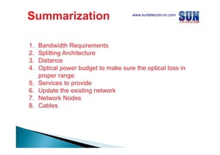
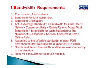
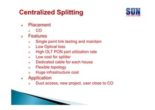
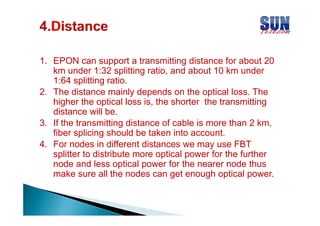
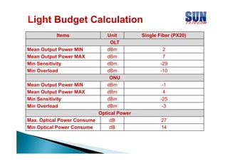
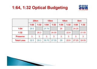
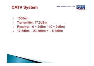
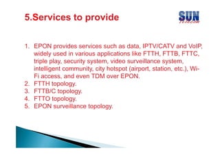
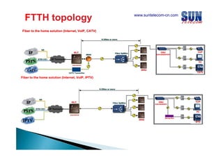
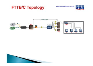
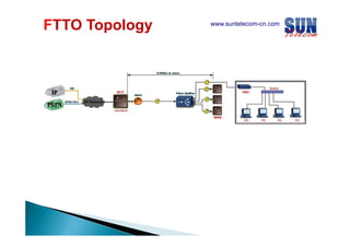
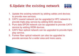
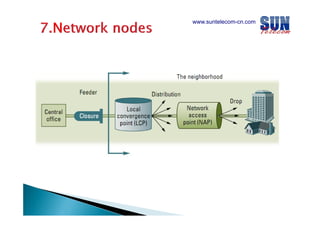
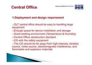
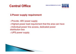
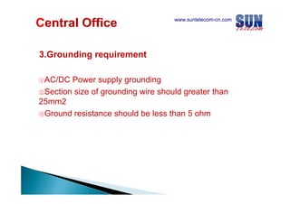


The document discusses considerations for designing an EPON network. It covers bandwidth requirements, splitting architecture options including 1-stage and 2-stage splitting, maximum transmission distances depending on splitting ratios, calculating the optical power budget, services that can be provided over EPON including FTTH and FTTB/C, upgrading existing networks, required network nodes and equipment, and cable types.


![Getting Started with Apache Spark: Big Data Made Simple [Free Meetup]](https://cdn.slidesharecdn.com/ss_thumbnails/apachesparkgettingstarted-260203175547-8361bcc3-thumbnail.jpg?width=640&height=640&fit=bounds)


