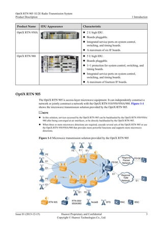
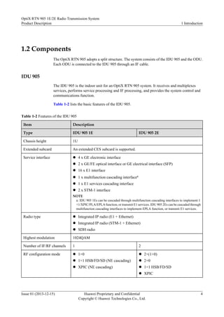
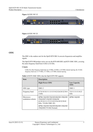
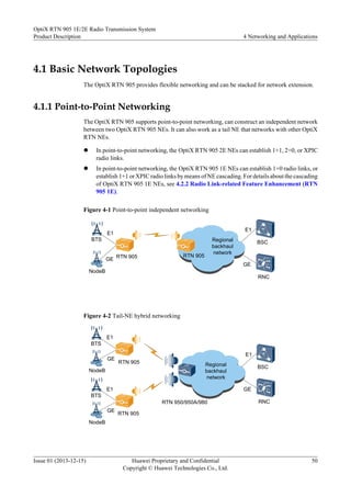
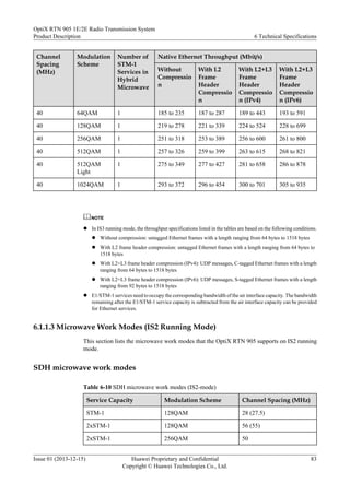
OptiX RTN 905 1E/2E Radio Transmission System
V100R006C10
Product Description
Issue 01
Date 2013-12-15
HUAWEI TECHNOLOGIES CO., LTD.
Copyright © Huawei Technologies Co., Ltd. 2013. All rights reserved.
No part of this document may be reproduced or transmitted in any form or by any means without prior written
consent of Huawei Technologies Co., Ltd.
Trademarks and Permissions
and other Huawei trademarks are trademarks of Huawei Technologies Co., Ltd.
All other trademarks and trade names mentioned in this document are the property of their respective holders.
Notice
The purchased products, services and features are stipulated by the contract made between Huawei and the
customer. All or part of the products, services and features described in this document may not be within the
purchase scope or the usage scope. Unless otherwise specified in the contract, all statements, information,
and recommendations in this document are provided "AS IS" without warranties, guarantees or representations
of any kind, either express or implied.
The information in this document is subject to change without notice. Every effort has been made in the
preparation of this document to ensure accuracy of the contents, but all statements, information, and
recommendations in this document do not constitute a warranty of any kind, express or implied.
Huawei Technologies Co., Ltd.
Address: Huawei Industrial Base
Bantian, Longgang
Shenzhen 518129
People's Republic of China
Website: http://www.huawei.com
Email: support@huawei.com
Issue 01 (2013-12-15) Huawei Proprietary and Confidential
Copyright © Huawei Technologies Co., Ltd.
i
About This Document
Related Versions
The following table lists the product versions related to this document.
Product Name Version
OptiX RTN 905 V100R006C10
iManager U2000 V200R001C00
Intended Audience
This document is intended for network planning engineers.
Familiarity with the basic knowledge related to digital microwave communication technology
will help you apply the information in this document.
Symbol Conventions
The symbols that may be found in this document are defined as follows.
Symbol Description
Indicates a hazard with a high level of risk,
which if not avoided, will result in death or
serious injury.
Indicates a hazard with a medium or low level
of risk, which if not avoided, could result in
minor or moderate injury.
OptiX RTN 905 1E/2E Radio Transmission System
Product Description About This Document
Issue 01 (2013-12-15) Huawei Proprietary and Confidential
Copyright © Huawei Technologies Co., Ltd.
ii
Symbol Description
Indicates a potentially hazardous situation,
which if not avoided, could result in
equipment damage, data loss, performance
degradation, or unexpected results.
Indicates a tip that may help you solve a
problem or save time.
Provides additional information to emphasize
or supplement important points of the main
text.
General Conventions
The general conventions that may be found in this document are defined as follows.
Convention Description
Times New Roman Normal paragraphs are in Times New Roman.
Boldface Names of files, directories, folders, and users are in
boldface. For example, log in as user root.
Italic Book titles are in italics.
Courier New Examples of information displayed on the screen are in
Courier New.
Update History
Updates between document issues are cumulative. Therefore, the latest document issue contains
all updates made in previous issues.
Updates in Issue 01 (2013-12-15) Based on Product Version V100R006C10
This document is the first release for the V100R006C10 product version.
OptiX RTN 905 1E/2E Radio Transmission System
Product Description About This Document
Issue 01 (2013-12-15) Huawei Proprietary and Confidential
Copyright © Huawei Technologies Co., Ltd.
iii
Contents
About This Document.....................................................................................................................ii
1 Introduction....................................................................................................................................1
1.1 Network Application......................................................................................................................................................2
1.2 Components....................................................................................................................................................................4
2 Functions and Features.................................................................................................................8
2.1 Microwave Types.........................................................................................................................................................10
2.1.1 Integrated IP Microwave...........................................................................................................................................10
2.1.2 SDH Microwave........................................................................................................................................................10
2.2 Modulation Strategy.....................................................................................................................................................11
2.2.1 Fixed Modulation......................................................................................................................................................11
2.2.2 Adaptive Modulation.................................................................................................................................................11
2.3 RF Configuration Modes..............................................................................................................................................14
2.4 Capacity........................................................................................................................................................................14
2.4.1 Air Interface Capacity...............................................................................................................................................14
2.4.2 Cross-Connect Capacity............................................................................................................................................15
2.4.3 Switching Capacity....................................................................................................................................................15
2.5 Interfaces......................................................................................................................................................................15
2.5.1 Service Interfaces......................................................................................................................................................15
2.5.2 Management and Auxiliary Ports..............................................................................................................................16
2.6 Cross-Polarization Interference Cancellation...............................................................................................................17
2.7 Automatic Transmit Power Control.............................................................................................................................18
2.8 MPLS/PWE3 Functions...............................................................................................................................................18
2.9 Ethernet Service Processing Capability........................................................................................................................19
2.10 QoS.............................................................................................................................................................................22
2.11 Clock Features............................................................................................................................................................23
2.12 Protection Capability..................................................................................................................................................24
2.13 Network Management................................................................................................................................................25
2.14 Easy Installation.........................................................................................................................................................26
2.15 Easy Maintenance.......................................................................................................................................................26
2.15.1 Equipment-level OAM............................................................................................................................................26
2.15.2 Packet Services OAM (TP-Assist)..........................................................................................................................28
2.16 Security Management.................................................................................................................................................30
OptiX RTN 905 1E/2E Radio Transmission System
Product Description Contents
Issue 01 (2013-12-15) Huawei Proprietary and Confidential
Copyright © Huawei Technologies Co., Ltd.
iv
2.17 Energy Saving.............................................................................................................................................................32
2.18 Environmental Protection...........................................................................................................................................32
3 Product Structure.........................................................................................................................33
3.1 System Architecture.....................................................................................................................................................34
3.2 Hardware Structure.......................................................................................................................................................35
3.2.1 IDU 905 1E/2E..........................................................................................................................................................35
3.2.2 ODU...........................................................................................................................................................................38
3.3 Software Structure........................................................................................................................................................39
3.4 Service Signal Processing Flow...................................................................................................................................40
3.4.1 Integrated IP radio.....................................................................................................................................................41
3.4.2 SDH Microwave........................................................................................................................................................43
3.4.3 Packet Microwave.....................................................................................................................................................46
4 Networking and Applications..................................................................................................49
4.1 Basic Network Topologies...........................................................................................................................................50
4.1.1 Point-to-Point Networking........................................................................................................................................50
4.1.2 Chain Networking......................................................................................................................................................51
4.1.3 Ring Networking.......................................................................................................................................................51
4.2 NE Cascading...............................................................................................................................................................52
4.2.1 Radio Link Direction Extension................................................................................................................................52
4.2.2 Radio Link-related Feature Enhancement (RTN 905 1E).........................................................................................54
4.2.3 Radio Link-related Feature Enhancement (RTN 905 2E).........................................................................................57
4.3 Feature Application (MPLS Packet Service)................................................................................................................59
4.3.1 CES Services.............................................................................................................................................................59
4.3.2 Ethernet Services.......................................................................................................................................................62
5 Network Management System..................................................................................................66
5.1 Network Management Solution....................................................................................................................................67
5.2 Web LCT......................................................................................................................................................................67
5.3 U2000...........................................................................................................................................................................69
6 Technical Specifications.............................................................................................................72
6.1 RF Performance............................................................................................................................................................73
6.1.1 Microwave Work Modes...........................................................................................................................................73
6.1.1.1 IF Running Modes and Microwave Work Modes..................................................................................................73
6.1.1.2 Microwave Work Modes (IS3 Running Mode)......................................................................................................75
6.1.1.3 Microwave Work Modes (IS2 Running Mode)......................................................................................................83
6.1.1.4 Throughput of an EPLA Group..............................................................................................................................88
6.1.2 Frequency Band.........................................................................................................................................................89
6.1.3 Receiver Sensitivity...................................................................................................................................................93
6.1.3.1 Receiver Sensitivity (IS3-mode)............................................................................................................................93
6.1.3.2 Receiver Sensitivity (IS2-mode)..........................................................................................................................108
6.1.4 Transceiver Performance.........................................................................................................................................118
OptiX RTN 905 1E/2E Radio Transmission System
Product Description Contents
Issue 01 (2013-12-15) Huawei Proprietary and Confidential
Copyright © Huawei Technologies Co., Ltd.
v
6.1.5 IF Performance........................................................................................................................................................127
6.1.6 Baseband Signal Processing Performance of the Modem.......................................................................................128
6.2 Predicted Equipment Reliability.................................................................................................................................128
6.2.1 Predicted Component Reliability.............................................................................................................................128
6.2.2 Predicted Link Reliability........................................................................................................................................129
6.3 Interface Performance.................................................................................................................................................129
6.3.1 SDH Interface Performance.....................................................................................................................................130
6.3.2 E1 Interface Performance........................................................................................................................................131
6.3.3 Ethernet Interface Performance...............................................................................................................................131
6.3.4 Auxiliary Interface Performance.............................................................................................................................135
6.4 Clock Timing and Synchronization Performance......................................................................................................136
6.5 Integrated System Performance..................................................................................................................................136
A Typical Configuration.............................................................................................................139
A.1 Typical RF Configuration Modes..............................................................................................................................140
B Compliance Standards.............................................................................................................141
B.1 ITU-R Standards........................................................................................................................................................142
B.2 ETSI Standards..........................................................................................................................................................143
B.3 IEC Standards............................................................................................................................................................144
B.4 ITU-T Standards........................................................................................................................................................145
B.5 IETF Standards..........................................................................................................................................................149
B.6 IEEE Standards..........................................................................................................................................................151
B.7 MEF Standards...........................................................................................................................................................152
B.8 AF Standards..............................................................................................................................................................152
B.9 Environmental Standards...........................................................................................................................................153
C Glossary......................................................................................................................................156
OptiX RTN 905 1E/2E Radio Transmission System
Product Description Contents
Issue 01 (2013-12-15) Huawei Proprietary and Confidential
Copyright © Huawei Technologies Co., Ltd.
vi
1Introduction
About This Chapter
The OptiX RTN 905 is a product in the OptiX RTN 900 radio transmission system series.
1.1 Network Application
The OptiX RTN 900 is a new generation TDM/Hybrid/Packet integrated microwave
transmission system developed by Huawei. It provides a seamless microwave transmission
solution for mobile communication network or private networks.
1.2 Components
The OptiX RTN 905 adopts a split structure. The system consists of the IDU 905 and the ODU.
Each ODU is connected to the IDU 905 through an IF cable.
OptiX RTN 905 1E/2E Radio Transmission System
Product Description 1 Introduction
Issue 01 (2013-12-15) Huawei Proprietary and Confidential
Copyright © Huawei Technologies Co., Ltd.
1
1.1 Network Application
The OptiX RTN 900 is a new generation TDM/Hybrid/Packet integrated microwave
transmission system developed by Huawei. It provides a seamless microwave transmission
solution for mobile communication network or private networks.
OptiX RTN 900 Product Family
The OptiX RTN 900 series provide a variety of service interfaces and can be installed easily and
configured flexibly. The OptiX RTN 900 series provide a solution that can integrate TDM
microwave, Hybrid microwave, and Packet microwave technologies according to the
networking scheme for the sites, achieving smooth upgrade from TDM microwave to Hybrid
microwave, and from Hybrid microwave to Packet microwave. This solution meets the
transmission requirements of 2G, 3G, and LTE services while also allowing for future network
evolution and convergence.
There are four types of OptiX RTN 900 V100R006C10 products: OptiX RTN 905, OptiX RTN
950, OptiX RTN 950A, and OptiX RTN 980. Users can choose the product best suited for their
site.
NOTE
Unless otherwise specified, OptiX RTN 905 mentioned in this document refers to OptiX RTN 905 1E/2E
newly released in V100R006C10. For details about OptiX RTN 905 1A/2A/1C, see OptiX RTN 905 1A/
2A/1C Product Description.
The OptiX RTN 910 does not provides V100R006C10 version.
Table 1-1 OptiX RTN 900 product family
Product Name IDU Appearance Characteristic
OptiX RTN 905 l 1 U high IDU.
l Five types of integrated chassis (1A/2A/1C/1E/2E).
l One or two microwave links.
OptiX RTN 910 l 1 U high IDU.
l Boards pluggable.
l Integrated service ports on system control,
switching, and timing boards.
l One or two IF boards.
OptiX RTN 950 l 2 U high IDU.
l Boards pluggable.
l 1+1 protection for system control, switching, and
timing boards.
l A maximum of six IF boards.
OptiX RTN 905 1E/2E Radio Transmission System
Product Description 1 Introduction
Issue 01 (2013-12-15) Huawei Proprietary and Confidential
Copyright © Huawei Technologies Co., Ltd.
2
Product Name IDU Appearance Characteristic
OptiX RTN 950A l 2 U high IDU.
l Boards pluggable.
l Integrated service ports on system control,
switching, and timing boards.
l A maximum of six IF boards.
OptiX RTN 980 l 5 U high IDU.
l Boards pluggable.
l 1+1 protection for system control, switching, and
timing boards.
l Integrated service ports on system control,
switching, and timing boards.
l A maximum of fourteen IF boards.
OptiX RTN 905
The OptiX RTN 905 is access-layer microwave equipment. It can independently construct a
network or jointly construct a network with the OptiX RTN 910/950/950A/980. Figure 1-1
shows the microwave transmission solution provided by the OptiX RTN 905.
NOTE
l In this solution, services accessed by the OptiX RTN 905 can be backhauled by the OptiX RTN 950/950A/
980 after being converged at air interfaces, or be directly backhauled by the OptiX RTN 905.
l When three or more microwave directions are required, cascade several sets of the OptiX RTN 905 or use
the OptiX RTN 950/950A/980 that provides more powerful functions and supports more microwave
directions.
Figure 1-1 Microwave transmission solution provided by the OptiX RTN 905
RTN 905 BTS
NodeB BSC
RNC
FE
E1
FE E1
E1
E1 FE
E1
E1
FE
FE/GE
E1
E1
FE/GE
RTN 950/
950A/980
Regional
TDM
Network
Regional
Packet
Network
OptiX RTN 905 1E/2E Radio Transmission System
Product Description 1 Introduction
Issue 01 (2013-12-15) Huawei Proprietary and Confidential
Copyright © Huawei Technologies Co., Ltd.
3
1.2 Components
The OptiX RTN 905 adopts a split structure. The system consists of the IDU 905 and the ODU.
Each ODU is connected to the IDU 905 through an IF cable.
IDU 905
The IDU 905 is the indoor unit for an OptiX RTN 905 system. It receives and multiplexes
services, performs service processing and IF processing, and provides the system control and
communications function.
Table 1-2 lists the basic features of the IDU 905.
Table 1-2 Features of the IDU 905
Item Description
Type IDU 905 1E IDU 905 2E
Chassis height 1U
Extended subcard An extended CES subcard is supported.
Service interface l 4 x GE electronic interface
l 2 x GE/FE optical interface or GE electrical interface (SFP)
l 16 x E1 interface
l 1 x multifunction cascading interfacea
l 1 x E1 services cascading interface
l 2 x STM-1 interface
NOTE
a: IDU 905 1Es can be cascaded through multifunction cascading interfaces to implement 1
+1/XPIC/PLA/EPLA function, or transmit E1 services. IDU 905 2Es can be cascaded through
multifunction cascading interfaces to implement EPLA function, or transmit E1 services.
Radio type l Integrated IP radio (E1 + Ethernet)
l Integrated IP radio (STM-1 + Ethernet)
l SDH radio
Highest modulation 1024QAM
Number of IF/RF channels 1 2
RF configuration mode l 1+0
l 1+1 HSB/FD/SD (NE cascading)
l XPIC (NE cascading)
l 2×(1+0)
l 2+0
l 1+1 HSB/FD/SD
l XPIC
OptiX RTN 905 1E/2E Radio Transmission System
Product Description 1 Introduction
Issue 01 (2013-12-15) Huawei Proprietary and Confidential
Copyright © Huawei Technologies Co., Ltd.
4
Figure 1-2 IDU 905 1E
Figure 1-3 IDU 905 2E
ODU
The ODU is the outdoor unit for the OptiX RTN 900. It converts frequencies and amplifies
signals.
The OptiX RTN 900 product series can use the RTN 600 ODU and RTN XMC ODU, covering
the entire frequency band from 6 GHz to 42 GHz.
NOTE
Unlike the other frequency bands that use 14 MHz, 28 MHz, or 56 MHz channel spacing, the 18 GHz
frequency band uses 13.75 MHz, 27.5 MHz, or 55 MHz channel spacing.
Table 1-3 RTN XMC ODUs that the OptiX RTN 905 supports
Item Description
High-Power ODU Low Capacity
ODU
ODU type XMC-2 XMC-1
Frequency band 6/7/8/10/10.5/11/13/15/18/23/26/28/32/38/4
2 GHz
7/8/11/13/15/18/23
GHz
Microwave
modulation scheme
QPSK/16QAM/32QAM/64QAM/128QAM/
256QAM/512QAM/1024QAM
(6/10/10.5/11/13/15/18/23/26/28/32/38/42
GHz, 7/8 GHz XMC-2E)
QPSK/16QAM/32QAM/64QAM/128QAM/
256QAM (7/8 GHz Normal)
QPSK/16QAM
OptiX RTN 905 1E/2E Radio Transmission System
Product Description 1 Introduction
Issue 01 (2013-12-15) Huawei Proprietary and Confidential
Copyright © Huawei Technologies Co., Ltd.
5
Item Description
High-Power ODU Low Capacity
ODU
Channel spacing 7/14/28/40/50/56 MHz
(6/7/8/10/11/13/15/18/23/26/28/32/38/42
GHz)
7/14/28 MHz (10.5 GHz)
3.5/7/14/28 MHz
Table 1-4 RTN 600 ODUs that the OptiX RTN 905 supports
Item Description
High-Power ODU Standard Power ODU
ODU type HP, HPA SP, SPA
Frequency band 6/7/8/10/10.5/11/13/15/18/2
3/26/28/32/38 GHz (HP)
6/7/8/11/13/15/18/23 GHz
(HPA)
7/8/11/13/15/18/23/26/38
GHz (SP ODU)
6/7/8/11/13/15/18/23 GHz
(SPA ODU)
Microwave modulation
scheme
QPSK/16QAM/32QAM/
64QAM/128QAM/256QAM
QPSK/16QAM/32QAM/
64QAM/128QAM/256QAM
Channel spacing 7/14/28/40/56 MHz
(6/7/8/10/11/13/15/18/23/26
/28/32/38 GHz)
7/14/28 MHz (10.5 GHz)
3.5/7/14/28 MHz
There are two methods for mounting the ODU and the antenna: direct mounting and separate
mounting.
l The direct mounting method is generally adopted when a small- or medium-diameter and
single-polarized antenna is used. In this situation, if one ODU is configured for one antenna,
the ODU is directly mounted at the back of the antenna. If two ODUs are configured for
one antenna, an RF signal combiner/splitter (hence referred to as a hybrid coupler) must
be mounted to connect the ODUs to the antenna. Figure 1-4 illustrates the direct mounting
method.
The direct mounting method can also be adopted when a small- or medium-diameter and
dual-polarized antenna is used. Two ODUs are mounted onto an antenna using an
orthomode transducer (OMT). The method for installing an OMT is similar to that for
installing a hybrid coupler.
OptiX RTN 905 1E/2E Radio Transmission System
Product Description 1 Introduction
Issue 01 (2013-12-15) Huawei Proprietary and Confidential
Copyright © Huawei Technologies Co., Ltd.
6
Figure 1-4 Direct mounting
l The separate mounting method is adopted when a large- or medium-diameter and single-
or dual-polarized antenna is used. Figure 1-5 shows the separate mounting method. In this
situation, a hybrid coupler can be mounted (two ODUs share one feed boom).
Figure 1-5 Separate mounting
NOTE
The OptiX RTN 905 provides an antenna solution that covers the entire frequency band, and supports
single-polarized antennas and dual-polarized antennas with diameters of 0.3 m to 3.7 m along with the
corresponding feeder system.
OptiX RTN 905 1E/2E Radio Transmission System
Product Description 1 Introduction
Issue 01 (2013-12-15) Huawei Proprietary and Confidential
Copyright © Huawei Technologies Co., Ltd.
7
2Functions and Features
About This Chapter
The OptiX RTN 905 provides a wide assortment of functions and features to ensure the quality
and efficiency of service transmission.
2.1 Microwave Types
The OptiX RTN 905 supports Integrated IP radio microwave and SDH microwave.
2.2 Modulation Strategy
OptiX RTN 905 supports fixed modulation and adaptive modulation.
2.3 RF Configuration Modes
The OptiX RTN 905 supports multiple RF configuration modes.
2.4 Capacity
The OptiX RTN 905 is a high-capacity device.
2.5 Interfaces
The OptiX RTN 905 provides a variety of interfaces.
2.6 Cross-Polarization Interference Cancellation
Cross-polarization interference cancellation (XPIC) technology is used together with co-channel
dual-polarization (CCDP). The application of the two technologies doubles the wireless link
capacity over the same channel. The OptiX RTN 905 2E supports XPIC function. The OptiX
RTN 905 1E supports XPIC function by means of NE cascading.
2.7 Automatic Transmit Power Control
Automatic transmit power control (ATPC) enables the output power of the transmitter to
automatically trace the level fluctuation at the receive end within the ATPC control range. This
feature reduces the interference with neighboring systems and residual BER.
2.8 MPLS/PWE3 Functions
The OptiX RTN 905 supports MPLS switching and Ethernet PWE3 function, therefore to
implement packet transmission of carrier-class services.
2.9 Ethernet Service Processing Capability
The OptiX RTN 905 has powerful Ethernet service processing capability.
OptiX RTN 905 1E/2E Radio Transmission System
Product Description 2 Functions and Features
Issue 01 (2013-12-15) Huawei Proprietary and Confidential
Copyright © Huawei Technologies Co., Ltd.
8
2.10 QoS
The OptiX RTN 905 provides improved quality of service (QoS) and supports the following
eight types of per-hop behaviors (PHBs): BE, AF1, AF2, AF3, AF4, EF, CS6, and CS7.
Therefore, network carriers can offer various QoS levels of service guarantees and build
networks that carry data, voice, and video services.
2.11 Clock Features
The OptiX RTN 905 supports physical-layer clock synchronization, time synchronization over
packet networks, and IEEE 1588v2 time synchronization, meeting the clock and time
synchronization requirements of mobile networks. In addition, the OptiX RTN 905 provides an
advanced clock protection mechanism.
2.12 Protection Capability
The OptiX RTN 905 provides a variety of protection schemes.
2.13 Network Management
The OptiX RTN 905 supports multiple network management (NM) modes and provides
comprehensive NM information exchange schemes.
2.14 Easy Installation
The OptiX RTN 905 supports several installation modes. That is, the installation is flexible and
convenient.
2.15 Easy Maintenance
The OptiX RTN 905 provides plentiful maintenance features.
2.16 Security Management
The OptiX RTN 905 can prevent unauthorized logins and operations, ensuring equipment
management security.
2.17 Energy Saving
The OptiX RTN 905 uses various types of technologies to reduce the amount of energy that the
device consumes. The device:
2.18 Environmental Protection
The OptiX RTN 905 is designed to meet or exceed environmental protection requirements. The
product complies with the RoHS directive and WEEE directive.
OptiX RTN 905 1E/2E Radio Transmission System
Product Description 2 Functions and Features
Issue 01 (2013-12-15) Huawei Proprietary and Confidential
Copyright © Huawei Technologies Co., Ltd.
9
2.1 Microwave Types
The OptiX RTN 905 supports Integrated IP radio microwave and SDH microwave.
2.1.1 Integrated IP Microwave
OptiX RTN 905 supports Integrated IP radio. Native TDM and Ethernet services can be
transmitted over the same microwave link. Ethernet services include Native Ethernet and ETH
PWE3 services.
Shown as Figure 2-1,the Integrated IP radio supported by OptiX RTN 905 has the following
features:
l Air interfaces can transmit E1/STM-1 services and Ethernet services simultaneously. E1/
STM-1 services are transmitted as Native TDM services. Ethernet services are transmitted
as Native Ethernet or ETH PWE3 services.
l Supports the AM function. E1 services and packet services can be configured with priority.
When AM is switched to the reference mode, the services with higher priority are
transmitted with preference.
Figure 2-1 Integrated IP radio
ODU
IDU
TDM
cross-connect
matrix
E1
Packet
switching
Layer2
Proccess
The Integrated IP radio
FE/GE
M
U
X
MPLS tunnel
Native E1/STM-1
Native Ethernet
(STM-1)
NOTE
The OptiX RTN 905 supports VLAN sub-interfaces, therefore transmitting MPLS Ethernet services and
Native Ethernet services over one port.
2.1.2 SDH Microwave
The OptiX RTN 905 can transmit 1xSTM-1 or 2xSTM-1 services over SDH microwave links.
The OptiX RTN 905 has a built-in MADM. The MADM grooms services to the microwave port
through cross-connections, maps the services into the STM-1-based or 2xSTM-1-based
microwave frames, and then transmits the frames. With this capability, services are flexibly
groomed and the optical network and the microwave network are seamlessly converged.
OptiX RTN 905 1E/2E Radio Transmission System
Product Description 2 Functions and Features
Issue 01 (2013-12-15) Huawei Proprietary and Confidential
Copyright © Huawei Technologies Co., Ltd.
10
Figure 2-2 SDH microwave
ODU
E1
IDU
MADM
SDH radio
SDH
OH
……
OH
……
2.2 Modulation Strategy
OptiX RTN 905 supports fixed modulation and adaptive modulation.
2.2.1 Fixed Modulation
Fixed modulation refers to a modulation policy in which a modulation scheme is adopted
invariably to provide constant air interface bandwidth for a running radio link.
When the OptiX RTN 905 uses fixed modulation, the modulation scheme and the channel
spacing can be set by using software.
l The SDH radio link uses fixed modulation.
l The Integrated IP radio link supports fixed modulation. Various combinations of
modulation schemes and channel spacings can be set.
2.2.2 Adaptive Modulation
The adaptive modulation (AM) technology adjusts the modulation scheme automatically based
on channel quality.
Modulation Scheme and Air-interface Capacity
When the AM technology is adopted, in the case of the same channel spacing, the microwave
service bandwidth varies according to the modulation scheme; the higher the modulation
efficiency, the higher the bandwidth of the transmitted services.
l When the channel quality is good (such as on days when weather conditions are favorable),
the equipment adopts a high-efficiency modulation scheme to transmit more user services.
This improves transmission efficiency and spectrum utilization of the system.
l When the channel quality deteriorates (such as on days with adverse weather), the
equipment adopts a low-efficiency modulation scheme to transmit only higher-priority
services within the available bandwidth while discarding lower-priority services. This
OptiX RTN 905 1E/2E Radio Transmission System
Product Description 2 Functions and Features
Issue 01 (2013-12-15) Huawei Proprietary and Confidential
Copyright © Huawei Technologies Co., Ltd.
11
method improves anti-interference capabilities of the radio link, which helps ensure the
link availability for higher-priority services.
Figure 2-3 Throughput at air interfaces of integrated IP radio (56 MHz channel)
Modulation Scheme Shift and Service Priorities
In Integrated IP radio mode, the equipment supports the AM technology. With configurable
priorities for E1 services and packet services, the transmission is controlled based on the service
bandwidth and QoS policies corresponding to the current modulation scheme. The highest-
priority services are transmitted with precedence.
l Priorities of E1 services
The priorities of E1 services are assigned based on the number of E1 services that each
modulation scheme can transmit. When modulation scheme switching occurs, only the E1
services whose number is specified in the new modulation scheme can be transmitted and
the excess E1 services are discarded.
l Priorities of packet services
With the QoS technology, packet services are scheduled to queues with different priorities.
The services in different queues are transmitted to the microwave port after running the
queue scheduling algorithm. When modulation scheme switching occurs, certain queues
may be congested due to insufficient capacity at the air interface. As a result, certain services
or all the services in these queues are discarded.
Adaptive Modulation
Figure 2-4 shows the service changes caused by shifts among six modulation schemes as an
example. The orange part indicates E1 services. The blue part indicates packet services. The
closer the service is to the outside of the cylinder in the figure, the lower the service priority.
Under all channel conditions, the service capacity varies according to the modulation scheme.
OptiX RTN 905 1E/2E Radio Transmission System
Product Description 2 Functions and Features
Issue 01 (2013-12-15) Huawei Proprietary and Confidential
Copyright © Huawei Technologies Co., Ltd.
12
When the channel conditions are unfavorable (during adverse weather conditions), lower-
priority services are discarded.
Figure 2-4 Adaptive modulation
Channel
Capability
E1 Services Ethernet Services
AM dowm-shift AM up-shift
Characteristics
The AM technology used by the OptiX RTN 905 has the following characteristics:
l The lowest-efficiency modulation scheme (also called reference scheme or modulation
scheme of guaranteed capacity) and the highest-efficiency modulation scheme (also called
nominal scheme or modulation scheme of full capacity) used by the AM can be configured.
– The OptiX RTN 905 supports 12 levels modulation schemes, including QPSK Strong,
QPSK, 16QAM Strong, 16QAM, 32QAM, 64QAM, 128QAM, 256QAM, 512QAM,
512QAM Light, 1024QAM, and 1024QAM Light. Strong and light indicate FEC coding
strength. Strong FEC improves receiver sensitivity by increasing error-correcting codes.
Light FEC expands service capacity by reducing error-correcting codes.
– The OptiX RTN 905 can work in IS2 running mode. When interconnect with an ISU2
or ISX2 board of RTN 910/950/950A/980, the OptiX RTN 905 works in IS2 running
mode and supports only six levels modulation schemes, including QPSK, 16QAM,
32QAM, 64QAM, 128QAM, and 256QAM.
l In AM, when modulation schemes are switched, the transmit frequency, receive frequency,
and channel spacing remain unchanged.
l In AM, modulation schemes are switched step-by-step.
l In AM, modulation scheme switching is hitless. When the modulation scheme is
downshifted, high-priority services will not be affected when low-priority services are
discarded. The switching is successful even when 100 dB/s channel fast fading occurs.
OptiX RTN 905 1E/2E Radio Transmission System
Product Description 2 Functions and Features
Issue 01 (2013-12-15) Huawei Proprietary and Confidential
Copyright © Huawei Technologies Co., Ltd.
13
2.3 RF Configuration Modes
The OptiX RTN 905 supports multiple RF configuration modes.
Table 2-1 shows the RF configuration modes supported by the OptiX RTN 905. For detail, refer
to Typical RF Configuration Modes.
Table 2-1 RF configuration modes
Equipment Type Configuration Mode
OptiX RTN 905 2E 2x(1+0) non-protection configuration
2+0 non-protection configuration
1+1 protection configuration (1+1 HSB/FD/SD)
XPIC configuration
OptiX RTN 905 1E 1+0 non-protection configuration
1+1 protection configuration (1+1 HSB/FD/SD, NE
cascading)
XPIC configuration (NE cascading)
2.4 Capacity
The OptiX RTN 905 is a high-capacity device.
2.4.1 Air Interface Capacity
The microwave air interface capacity depends on the microwave working mode.
Table 2-2 and Table 2-3 lists the microwave air interface capacities that the OptiX RTN 905
supports.
Table 2-2 Air interface capacities (Integrated IP radio)
Equipment Type Maximum Number of
E1s (E1 + Ethernet)
Maximum Number of
STM-1 (STM-1 +
Ethernet)
Maximum Ethernet
Throughput at Air
Interfaces (Mbit/s)
OptiX RTN 905 63 1 480 to 609 (none-XPIC)
450 to 575 (XPIC)
NOTE
l OptiX RTN 905 support frame header compression at air interfaces, and their equivalent throughout of Ethernet services at
air interfaces can reach up to 1000 Mbit/s. For details, see Microwave Work Modes.
l The XPIC function doubles the service capacity of the microwave channel at the same frequency bandwidth.
OptiX RTN 905 1E/2E Radio Transmission System
Product Description 2 Functions and Features
Issue 01 (2013-12-15) Huawei Proprietary and Confidential
Copyright © Huawei Technologies Co., Ltd.
14
Table 2-3 Air interface capacities (SDH radio)
Equipment Type Maximum Air Interface Capacity
OptiX RTN 905 2×STM-1
NOTE
The XPIC function doubles the service capacity of the microwave channel at the same frequency bandwidth.
2.4.2 Cross-Connect Capacity
The OptiX RTN 905 provides a maximum of VC-12/VC-3/VC-4 cross-connections equivalent
to 8x8 VC-4s.
2.4.3 Switching Capacity
The OptiX RTN 905 has a built-in packet switching platform with the switching capacity of
8Gbit/s.
2.5 Interfaces
The OptiX RTN 905 provides a variety of interfaces.
2.5.1 Service Interfaces
OptiX RTN 905 provides Ethernet interfaces, PDH/SDH interfaces, and service cascading
interfaces.
Table 2-4 lists the the types and quantity of service interfaces that the OptiX RTN 905provides.
Table 2-4 Types and quantity of service interfaces
Service Interface Quantity
IDU 905 1E/2E
GE electrical interface (RJ45): 10/100/1000BASE-T(X) 4
GE/FE optical interface (SFP) or GE electrical interface
(SFP):
l GE optical interface: 1000BASE-SX/LX/VX/ZX/BX
l FE optical interface: 100BASE-FX/LX/VX/ZX/BX
l GE electrical interface: 10/100/1000BASE-T(X)
2
75-ohm or 120-ohm E1 interface 16
STM-1 electrical interface (SFP) or
STM-1 optical interface (SFP): Ie-1, S-1.1, L-1.1, L-1.2
2
OptiX RTN 905 1E/2E Radio Transmission System
Product Description 2 Functions and Features
Issue 01 (2013-12-15) Huawei Proprietary and Confidential
Copyright © Huawei Technologies Co., Ltd.
15
Service Interface Quantity
IDU 905 1E/2E
Service cascading interface (SFP) 2
NOTE
The first and second GE electrical interfaces on the IDU 905 2E support P&E power over Ethernet.
2.5.2 Management and Auxiliary Ports
OptiX RTN 905 provides various management and auxiliary ports.
Management and Auxiliary Ports
Table 2-5 Types and number of management and auxiliary ports
Port Description Quantity
External clock
port
2,048 kbit/s or 2048 kHz external clock input/output
port
1
External time
port
External time input or output port (RS-422 level,
1PPS+TOD or DCLS format)
1
Management
port
10/100BASE-T(X) NM port 1
NM serial port 1
10/100BASE-T(X) NM cascading port 1
Auxiliary port RS-232 asynchronous data port 1
Alarm port Alarm input port 3
Alarm output port 1
Outdoor
cabinet
monitoring port
RS-485 outdoor cabinet monitoring port 1
Type-A USB
port
USB port for USB flash drive, supporting database
backup, database restoration, and NE software
upgrades using a USB flash drive
1
Mini USB port USB port for NMS, supporting NE management when
the Web LCT is connected.
1
NOTE
The external clock port, external time port, and outdoor cabinet monitoring port share one RJ45 connector.
The external clock and outdoor cabinet monitoring functions can be enabled simultaneously, but the
external time function must be enabled alone. This external clock port can also transparently transmit the
overhead bytes (DCC bytes and asynchronous data byte) or wayside E1, however, this port can implement
only one function at a time.
OptiX RTN 905 1E/2E Radio Transmission System
Product Description 2 Functions and Features
Issue 01 (2013-12-15) Huawei Proprietary and Confidential
Copyright © Huawei Technologies Co., Ltd.
16
Auxiliary Service Channel
Auxiliary services and NM messages are transmitted by overhead bytes over a radio link. For
details, see Table 2-6.
Table 2-6 Auxiliary services channels provided by each microwave port
Service/Message Type Microwave Frame Overhead
Quantity of
Paths
Path Rate
Asynchronous data service 1 ≤ 19.2 kbit/s
DCC channel 1 192 kbit/s
Wayside E1 service 1 2048 kbit/s (in the SDH radio link)
2.6 Cross-Polarization Interference Cancellation
Cross-polarization interference cancellation (XPIC) technology is used together with co-channel
dual-polarization (CCDP). The application of the two technologies doubles the wireless link
capacity over the same channel. The OptiX RTN 905 2E supports XPIC function. The OptiX
RTN 905 1E supports XPIC function by means of NE cascading.
CCDP transmission adopts a horizontally polarized wave and a vertically polarized wave on one
channel to transmit two channels of signals. Ideally, for CCDP transmissions, there will not be
any interference between the two orthogonal signals although they are on the same frequency.
In actual practice, despite the orthogonality of the two signals, interference between the signals
inevitably occurs due to cross-polarization discrimination (XPD) of the antenna and channel
degradation. To cancel the interference, XPIC technology is used to receive signals horizontally
and vertically. The signals in the two directions are then processed and the original signals are
recovered from interfered signals.
Figure 2-5 CCDP channel configuration , used when XPIC is used
H
V
Modem
ODU 1
ODU 2
f1
f1
ODU 1
ODU 2
f1
f1
Site A Site B
f1
Modem
Modem
Modem
Service
Service
Service
Service
V: vertical polarization direction
H: horizontal polarization direction
Service singnal
OptiX RTN 905 1E/2E Radio Transmission System
Product Description 2 Functions and Features
Issue 01 (2013-12-15) Huawei Proprietary and Confidential
Copyright © Huawei Technologies Co., Ltd.
17
2.7 Automatic Transmit Power Control
Automatic transmit power control (ATPC) enables the output power of the transmitter to
automatically trace the level fluctuation at the receive end within the ATPC control range. This
feature reduces the interference with neighboring systems and residual BER.
Figure 2-6 Relationship between the RSL and TSL
T
Up-fading
Down-fading
2 dB
TSL/RSL
TSL
RSL
2 dB
Central value of the ATPC
upper threshold and the
ATPC lower threshold
2.8 MPLS/PWE3 Functions
The OptiX RTN 905 supports MPLS switching and Ethernet PWE3 function, therefore to
implement packet transmission of carrier-class services.
Table 2-7 MPLS/PWE3 functions
Function and Feature Description
MPLS
tunnel
Setup mode Static LSPs
Bearer mode l Ethernet port
l IP microwave port
l MLPPP link
Protection 1:1 MPLS tunnel APS
OAM l MPLS OAM that complies with ITU-T Y.
1710 and ITU-T Y.1711
l MPLS-TP LSP OAM that complies with
ITU-T Y.1731
l LSP ping and LSP traceroute functions
OptiX RTN 905 1E/2E Radio Transmission System
Product Description 2 Functions and Features
Issue 01 (2013-12-15) Huawei Proprietary and Confidential
Copyright © Huawei Technologies Co., Ltd.
18
Function and Feature Description
PWE3 ETH PWE3 Encapsulation
mode
l Raw mode
l Tagged mode
Service type l E-Line
l E-Aggr
l E-LAN (VPLS)
TDM PWE3 Emulation
mode
l SAToP
l CESoPSN
Packet loading
time
125 μs to 5000 μs
Jitter
compensation
buffering time
375 μs to 16000 μs
Setup mode Static PWs
Control Word supported
Numbers of PWs Supports a maximum of 1024 PWs.
Protection 1:1 PW APS
OAM l PW OAM that complies with ITU-T Y.
1710 and ITU-T Y.1711
l MPLS-TP PW OAM that complies with
ITU-T Y.1731
l VCCV
l PW ping and PW traceroute functions
l ITU-T Y.1731-compliant packet loss
measurement, delay measurement, and
delay variation measurement
l Intelligent service fault diagnosis
MS-PW Supported
Configurable bandwidth Supported
2.9 Ethernet Service Processing Capability
The OptiX RTN 905 has powerful Ethernet service processing capability.
OptiX RTN 905 1E/2E Radio Transmission System
Product Description 2 Functions and Features
Issue 01 (2013-12-15) Huawei Proprietary and Confidential
Copyright © Huawei Technologies Co., Ltd.
19
Table 2-8 Ethernet service processing capability
Item Description
Ethernet service
type
l Native Ethernet services: E-Line service and E-LAN service
l PW-carried Ethernet services: E-Line service, E-Aggr service, and
E-LAN (VPLS) service
Range of
maximum frame
length
1518 bytes to 9600 bytes
VLAN l Adds, deletes, and switches VLAN tags that comply with IEEE
802.1q/p, and forwards packets based on VLAN tags.
l Processes packets based on the port tag attribute (Tag/Hybrid/
Access).
l The VLAN ID ranges from 1 to 4094.
MAC address l The E-LAN service supports the MAC address self learning
capability in two learning modes: SVL and IVL.
l MAC addresses can be filtered; that is, MAC addresses can be
blacklisted.
l Static MAC address entries can be set.
l The capacity of the MAC address table is 16 k (including static
entities and blacklist entities).
l The MAC address aging time can be configured.
Spanning tree Supports the MSTP protocol, and generates only the Common and
Internal Spanning Tree (CIST). The functions of the MSTP protocol are
equal to those of the RSTP protocol.
IGMP Snooping Supported
Link aggregation
(LAG)
The OptiX RTN 905 1E provides LAG protection for Ethernet ports. The
OptiX RTN 905 2E provides LAG protection for Ethernet ports and radio
ports.
l Supports manual aggregation and static aggregation
l Supports load sharing and non-load sharing.
l The load sharing hash algorithm is implemented based on MAC
addresses, IP addresses, or MPLS labels, and supports the specified
mode and automatic mode.
Physical link
aggregation
(PLA)
The OptiX RTN 905 2E supports the PLA/EPLA function. The OptiX
RTN 905 1E supports the PLA/EPLA function by NE cascading.
PLA and EPLA are Layer 1 link aggregation group (L1 LAG)
technology, which shares load based on the bandwidth at the physical
layer to achieve link aggregation.
A PLA group supports a maximum of two member links. An EPLA
group supports a maximum of four member links.
OptiX RTN 905 1E/2E Radio Transmission System
Product Description 2 Functions and Features
Issue 01 (2013-12-15) Huawei Proprietary and Confidential
Copyright © Huawei Technologies Co., Ltd.
20
Item Description
ERPS Supports ITU-T G.8032v1/v2-compliant single-ring or multi-ring
network protection for Ethernet services.
LPT Disables the remote Ethernet port that is connected to the user equipment
when the transmission network or local port fails.
QoS Supports QoS. For details, see 2.10 QoS.
Traffic control
function
Supports the IEEE 802.3x-compliant traffic control function.
ETH-OAM l Supports IEEE 802.1ag- and IEEE 802.3ah-compliant ETH-OAM
functions.
l Supports ITU-T Y.1731-compliant ETH-OAM functions, supports
packet loss measurement, delay measurement, and delay variation
measurement.
Ethernet
performance
monitoring
l Supports IETF RFC2819-compliant RMON performance
monitoring.
l Measures real-time and historical traffic and bandwidth utilization
for ports.
l Measures real-time and historical performance events for DS
domains, flows, VLANs, traffics on UNI side, PWs, and egress
queues.
l Measures packet loss due to congestion for flows.
l Measures packet loss due to congestion for PWs and egress queues.
Synchronous
Ethernet
Supports ITU-T G.8261- and ITU-T G.8262-compliant synchronous
Ethernet.
NOTE
l The E-Line service is an Ethernet private line service. The OptiX RTN 905 supports a maximum of 1024
E-Line services.
l For Native Ethernet services, the OptiX RTN 905 supports E-Line services based on the port, port
+VLAN, and port+QinQ.
l For PW-carried Ethernet services, the OptiX RTN 905 supports E-Line services based on the port, and
port+VLAN.
l The E-Aggr service is an Ethernet aggregation service. The OptiX RTN 905 supports E-Aggr services from
multiple UNIs to one PW and E-Aggr services from multiple PWs to one UNI. The OptiX RTN 905supports
a maximum of 128 E-Aggr services.
l The E-LAN service is an Ethernet local area network (LAN) service.
l For Native Ethernet services, the OptiX RTN 905 supports the E-LAN service based on the 802.1d
bridge, 802.1q bridge, and 802.1ad bridge. The bridge supports a maximum of 1024 logical ports.
l For PW-carried Ethernet services, the OptiX RTN 905 supports virtual private LAN services (VPLS)
based on virtual switch instances (VSI). The OptiX RTN 905 supports a maximum of 16 VSIs and 512
logical ports.
OptiX RTN 905 1E/2E Radio Transmission System
Product Description 2 Functions and Features
Issue 01 (2013-12-15) Huawei Proprietary and Confidential
Copyright © Huawei Technologies Co., Ltd.
21
2.10 QoS
The OptiX RTN 905 provides improved quality of service (QoS) and supports the following
eight types of per-hop behaviors (PHBs): BE, AF1, AF2, AF3, AF4, EF, CS6, and CS7.
Therefore, network carriers can offer various QoS levels of service guarantees and build
networks that carry data, voice, and video services.
Table 2-9 QoS features
Feature Performance
DiffServ For Ethernet services, supports mapping the Ethernet service into
different PHB service levels based on the C-VLAN priority, S-VLAN
priority, IP DSCP value, and MPLS EXP value.
Traffic
classification
Supports port traffic classification based on MAC address, VLAN ID,
VLAN priority, IP address, DSCP, protocol type, Port number and ICMP
type.
Traffic policing Supports flow-based traffic policing and the setting of PIR and CIR in
steps of 64 kbit/s.
Queue scheduling l Each Ethernet port or Integrated IP radio port supports eight levels
of priority scheduling.
l Flexibly sets the queue scheduling scheme for each Ethernet port and
Integrated IP radio port. The queue scheduling modes include SP, SP
+WRR, and WRR.
Congestion
avoidance
Drops packets in tail drop mode or weighted random early detection
(WRED) mode.
Traffic shaping l Supports the shaping for the specified port, priority queue, or service
flow.
l Supports a step of 64 kbit/s for the PIR and CIR.
Figure 2-7 Typical QoS application (Native Ethernet services)
Fowarding
Queues Scheduling
Classifing
Ingress Egress
Packet
Switching
CS7
CS6
EF
AF4
AF3
AF2
AF1
BE
Policing
CAR
Flow
Mapping
DiffServ
Shaping
Shaping
OptiX RTN 905 1E/2E Radio Transmission System
Product Description 2 Functions and Features
Issue 01 (2013-12-15) Huawei Proprietary and Confidential
Copyright © Huawei Technologies Co., Ltd.
22
2.11 Clock Features
The OptiX RTN 905 supports physical-layer clock synchronization, time synchronization over
packet networks, and IEEE 1588v2 time synchronization, meeting the clock and time
synchronization requirements of mobile networks. In addition, the OptiX RTN 905 provides an
advanced clock protection mechanism.
Clock synchronization
Table 2-10 Clock synchronization features
Item Description
Equipment clock Supports tracing mode and free-run mode. In addition, it
supports the holdover mode when an MN1 subcard is
equipped.
Clock synchronization Supports the following clock sources:
l SDH line clock
l E1 tributary clock
l Radio link clock
l Synchronous Ethernet clock
l Service cascading interface clock
l 2048 kbit/s or 2048 kHz external clock
l IEEE 1588v2 clock
l IEEE 1588 ACR clock (when an MN1 subcard is
equipped)
SSM protocol/Extended
SSM protocol
Supported. SSM information can be transmitted in the
following interfaces:
l SDH line
l Radio link
l Synchronization Ethernet interface
l Service cascading interface
l 2048 kbit/s external clock interface, supporting the SSM
protocol and not supporting the extended SSM protocol
Tributary clock l Supports retiming for E1 services.
l Supports the transparent transmission of E1 clocks.
l Supports CES ACR clocks (when an MN1 subcard is
equipped).
Output of the external clock Supported (2048 kbit/s or 2048 kHz mode)
OptiX RTN 905 1E/2E Radio Transmission System
Product Description 2 Functions and Features
Issue 01 (2013-12-15) Huawei Proprietary and Confidential
Copyright © Huawei Technologies Co., Ltd.
23
Time synchronization
Table 2-11 Time synchronization features
Item Description
Clock Model OC, BC, TC, TC+BC
Input of the external
time
Supported
Time source
selection and
protection
l BMC algorithm
l Static selection for time sources
Time
synchronization
Supports the following time sources:
l IEEE 1588v2 clock
l External time interface
Time transparent
transmission
Transparent transmission of IEEE 1588v2 time signals
Output of the
external time
Supported
2.12 Protection Capability
The OptiX RTN 905 provides a variety of protection schemes.
Table 2-12 Protection schemes
Item Description
Equipment-
level protection
Power input 1+1 hot backup
Radio link 1+1 HSB/SD/FD protection
Network-level
protection
MPLS MPLS tunnel 1:1 protection
PW PW 1:1 Protection
Ethernet LAG protection
ERPS protection
MSTP protection
PLA/EPLA protection
E1 SNCP protection
STM-1 1+1 or 1:1 linear multiplex section protection
OptiX RTN 905 1E/2E Radio Transmission System
Product Description 2 Functions and Features
Issue 01 (2013-12-15) Huawei Proprietary and Confidential
Copyright © Huawei Technologies Co., Ltd.
24
Item Description
NOTE
OptiX RTN 950 1Es support 1+1 HSB/SD/FD protection and PLA/EPLA protection through NE
cascading.
2.13 Network Management
The OptiX RTN 905 supports multiple network management (NM) modes and provides
comprehensive NM information exchange schemes.
NM Mode
The OptiX RTN 905 supports the following NM modes:
l Per-NE management (for example, management of a local NE or a remote NE) by the
iManager Web LCT
l Central management of OptiX RTN NEs and other OptiX NEs by the iManager U2000
l SNMP agent-based management, which allows operators to query alarms, performance
events, NE parameters and service parameters by performing SNMP GET operations, and
to configure NE parameters and service parameters by performing SNMP SET operations
LLDP Function
The OptiX RTN 905 and another device (such as a base station) that are both enabled with the
Link Layer Discovery Protocol (LLDP) can discover each other. The LLDP function helps to
archive:
l Display of the topology of a network that comprises different types of equipment on an
NMS.
l Simplified fault diagnosis.
NM Information Exchange Schemes
The OptiX RTN 905 supports inband DCN and outband DCN.
Table 2-13 DCN information exchange schemes
Item Specifications
DCN
channe
l
DCC
bytes
Integrated IP
radio
Three DCC bytes that are defined by Huawei
SDH
microwave
D1-D3, D4-D12, or D1-D12 bytes
SDH line D1-D3, D4-D12, or D1-D12 bytes
Cascading port Supports the transmission of DCC bytes
OptiX RTN 905 1E/2E Radio Transmission System
Product Description 2 Functions and Features
Issue 01 (2013-12-15) Huawei Proprietary and Confidential
Copyright © Huawei Technologies Co., Ltd.
25
Item Specifications
External clock
port
Supports the transmission of DCC bytes
Network management port Supports one network management Ethernet port or
one network management Ethernet cascade port.
Inband
DCN
Radio link The inband DCN channel is marked with the VLAN
tag and its bandwidth is configurable.
FE/GE port The inband DCN channel is marked with the VLAN
tag and its bandwidth is configurable.
Networ
k
manag
ement
protoc
ol
HWECC protocol Supported
IP protocols Supported
L2 DCN Supported
2.14 Easy Installation
The OptiX RTN 905 supports several installation modes. That is, the installation is flexible and
convenient.
The IDU can be installed on the following types of cabinets and surfaces:
l In a 300 mm or 600 mm ETSI cabinet
l In a 450 mm or 600 mm 19-inch cabinet
l In an open cabinet
l In an outdoor cabinet
l On a wall
l On a table
The ODU supports two installation modes: direct mounting and separate mounting.
2.15 Easy Maintenance
The OptiX RTN 905 provides plentiful maintenance features.
2.15.1 Equipment-level OAM
The OptiX RTN 905 provides several maintenance features that effectively reduce the costs
associated with maintaining the equipment.
Table 2-14 describes the OAM functions supported by the OptiX RTN 905.
OptiX RTN 905 1E/2E Radio Transmission System
Product Description 2 Functions and Features
Issue 01 (2013-12-15) Huawei Proprietary and Confidential
Copyright © Huawei Technologies Co., Ltd.
26
Table 2-14 Equipment-level OAM
Function Description
Management and
monitoring
l The OptiX RTN 905 can be managed together with optical
transmission equipment by the U2000.
l Supports various alarms and performance events.
l Supports RMON performance statistics on various types of
objects.
l Supports the monitoring and graphic display of key radio
transmission performance indicators such as microwave transmit
power, received power, signal to noise ratio (SNR), and air-
interface BER.
l Supports the monitoring and graphic display of Ethernet
performance specifications such as port traffic and bandwidth
utilization.
Hardware
maintenance
l All the indicators and cable interfaces are available on the front
panel of the IDU.
Diagnosis and
Testing
l Supports PRBS tests by IF ports.
l Supports PRBS tests by E1 ports.
l Simulates Ethernet meters to test packet loss, delay, and
throughput.
l Supports various loopback types over service ports and IF ports.
Packet service OAM l Supports IEEE 802.1ag- and IEEE 802.3ah-compliant ETH OAM
functions.
l Supports ITU-T Y.1731-compliant packet loss measurement,
delay measurement, and delay variation measurement for Ethernet
services.
l Supports the ITUT-T Y.1711-compliant MPLS OAM function
and LSP ping/traceroute.
l Supports the ITUT-T Y.1711-compliant PW OAM function and
PW ping/traceroute.
l Supports the ITU-T Y.1731-compliant MPLS-TP LSP OAM and
PW OAM functions.
Database
management
l Remotely backs up and restores the NE database by using the
U2000.
l Supports database backup and restoration from a USB flash drive.
l Two copies of software and data are stored in the flash memory
of the system control, switching, and timing board to meet the
smooth upgrade requirements.
OptiX RTN 905 1E/2E Radio Transmission System
Product Description 2 Functions and Features
Issue 01 (2013-12-15) Huawei Proprietary and Confidential
Copyright © Huawei Technologies Co., Ltd.
27
Function Description
Software
management
l Remotely loads NE software and data by using the U2000 and
provides a quick NE upgrade solution.
l Upgrades NE software from a USB flash drive.
l Supports the NSF function. E1 services and Ethernet E-Line
services are not interrupted during warm resets on NE software.
l Supports hot patch loading. Users can upgrade software without
interrupting services.
l Supports software version rollback so that original system services
are restored despite software upgrade failures.
2.15.2 Packet Services OAM (TP-Assist)
The OptiX RTN 905 works with the iManager U2000 to allow hierarchy OAM of packet
services. Packet OAM supports end-to-end service configuration, acceptance tests, and fault
locating, therefore simplifying operation and maintenance of packet services.
Table 2-15 describes the packet OAM functions supported by the OptiX RTN 905.
Table 2-15 Packet OAM (TP-Assist)
OAM Stage Subitem Description
End-to-end
service
configuration
End-to-end packet
service
configuration
l Supports end-to-end configuration of Native E-
Line/E-LAN services.
l Supports end-to-end configuration of MPLS
tunnel and ETH PWE3.
Automatic
deployment of
alarm
management
l Automatically configures end-to-end ETH
OAM during Native Ethernet service
configuration and supports connectivity tests
and alarm reporting.
l Automatically configures end-to-end MPLS-
TP OAM during MPLS tunnel service
configuration and supports connectivity tests
and alarm reporting.
l Automatically configures end-to-end ETH-
OAM during ETH PWE3 service configuration
and supports connectivity tests and alarm
reporting.
Acceptance tests Service
connectivity tests
l Supports one-click connectivity test of Native
E-Line and E-LAN services.
l Supports one-click connectivity test of the E-
Line services carried by MPLS tunnels.
OptiX RTN 905 1E/2E Radio Transmission System
Product Description 2 Functions and Features
Issue 01 (2013-12-15) Huawei Proprietary and Confidential
Copyright © Huawei Technologies Co., Ltd.
28
OAM Stage Subitem Description
Service
performance tests
l Supports one-click test on packet loss, delay,
and delay jitter of Native E-Line and E-LAN
services.
l Supports one-click test on packet loss, delay,
and delay jitter of the E-Line services carried
by MPLS tunnels.
l Simulates Ethernet meters to test packet loss,
delay, and throughput.
Fault locating Port IP ping l Supports local ping at UNI ports.
l Supports remote ping at UNI ports.
Port monitoring l Reports alarms indicating Ethernet signal loss.
l Reports alarms indicating Ethernet port auto-
negotiation failures (half-duplex alarm).
Service loopback
detecting
l Detects loopbacks in E-Line services.
l Automatically disables the service ports
involved in a loop.
Intelligent fault
diagnosis
l Checks the integrity of hardware, software, and
configuration along a service path.
l Detects zero traffic and packet loss along a
service path.
Performance
statistics
l Measures real-time and historical performance
events for Ports, DS domains, flows, VLANs,
UNI-side services, PWs, tunnel, and egress
queues.
l Measures packet loss due to congestion for
flows, PWs bandwidth, and egress queues.
Performance
monitoring
l Reports packet loss threshold-crossing alarms
by DS domain, traffic classification, VLAN, V-
UNI, PW, and egress queue.
l Reports port bandwidth utilization threshold-
crossing alarms.
l Reports packet loss threshold-crossing alarms
for flows, PWs bandwidth, and egress queues.
l Reports zero-traffic alarms for Ports, DS
domains, flows, VLANs, UNI-side services,
PWs, and egress queues.
OptiX RTN 905 1E/2E Radio Transmission System
Product Description 2 Functions and Features
Issue 01 (2013-12-15) Huawei Proprietary and Confidential
Copyright © Huawei Technologies Co., Ltd.
29
2.16 Security Management
The OptiX RTN 905 can prevent unauthorized logins and operations, ensuring equipment
management security.
Hardware Security
The OptiX RTN 905 adopts high-reliability hardware design to ensure that the system runs
properly under security threats.
The following hardware preventive measures are provided:
l Microwave interfaces: The FEC encoding mode is adopted and the adaptive time-domain
equalizer for baseband signals is used. This enables the microwave interfaces to tolerate
strong interference. Therefore, an interceptor cannot restore the contents in a data frame if
coding details and service configurations are not obtained.
l Modular design: Control units are separated from service units and service units are
separated from each other. In this manner, a fault on any unit can be properly isolated,
minimizing the impact of the fault on other units in the system.
l CPU flow control: Data flow sent to the CPU for processing is classified and controlled to
prevent the CPU from being attacked by a large number of packets. This ensures that the
CPU operates properly under attacks.
Software Security
The OptiX RTN 905 processes two categories of data: O&M data and service data. The preceding
data is transmitted over independent paths and does not affect each other. Therefore, services
on the OptiX RTN 950 are processed on two planes:
l Management plane
The management plane provides access to the required equipment and management
functions, such as managing accounts and passwords, communication protocols, and alarm
reporting. The security feature of the management plane enables secure device access,
concentrated management, and thorough security audit.
l Data plane
The data plane processes service data that enters the devices and forwards service data
packets according to hardware forwarding entries. On one hand, the data plane prevents
user service packets from being intercepted, modified, or deleted, which endangers the
confidentiality and completeness of user data. On the other hand, the data plane ensures
the control of hardware forwarding actions, preventing forwarding entries from being
attacked or modified. In this manner, the forwarding plane of the devices can function stably
and reliably.
Table 2-16lists the security functions provided by the OptiX RTN 905.
OptiX RTN 905 1E/2E Radio Transmission System
Product Description 2 Functions and Features
Issue 01 (2013-12-15) Huawei Proprietary and Confidential
Copyright © Huawei Technologies Co., Ltd.
30
Table 2-16 Security functions of the three planes
Plane Function Description
Managemen
t plane
Account and
password
management
Manages and saves device maintenance accounts.
Local
authentication and
authorization
Checks account validity and performs authorization.
RADIUS
authorization and
authentication
Checks account validity and remotely performs
authorization in the concentrated mode, reducing the
maintenance cost.
Security log Records actions about account management.
Operation log Records non-query operations.
SYSLOG
Management
Functions as a standard solution for saving logs offline,
effectively resolving the deficient saving space
problem.
TCP/IP protocol
stack attack
prevention
Provides basic TCP/IP attack prevention capability,
such as attacks from incorrect IP packets, ICMP ping/
jolt, and DoS.
Access Control List
(ACL)
Provides ACL based on IP addresses and port numbers.
SSL/TLS
encryption
communication
Supports SSL3.0/TLS1.0 and provides secure
encrypted tunnels based on security certifications.
SSH security
communication
Provides the SSHv2 server and SFTP client service.
OSPF route
protocol
Provides OSPFv2, capable of standard MD5
authentication.
NTP protocol Provides NTPv3, capable of MD5 authentication and
authorization control.
SNMP management
protocol
Provides SNMPv3, capable of security authentication
and data encryption functions.
Data plane Flow control Monitors port traffic. Suppresses multicast packets,
discards unknown unicast/multicast packets, and uses
QoS to control service traffic.
Discarding of error
packets
Discards invalid error packets. For example, a packet
whose size is smaller than 46 bytes.
OptiX RTN 905 1E/2E Radio Transmission System
Product Description 2 Functions and Features
Issue 01 (2013-12-15) Huawei Proprietary and Confidential
Copyright © Huawei Technologies Co., Ltd.
31
Plane Function Description
Loop avoidance Detects loopback at services ports, blocks loopback,
and supports service loopback detection of Ethernet
ports.
Layer 2 service
access control
Provides the access control capabilities: filtering of
static MAC addresses, blacklist, learning and
forbidding of MAC addresses, and filtering based on
complex traffic classification.
Service isolation Provides three isolation methods: Layer 2 logical
isolation, horizontal isolation, and physical isolation.
Strict isolation of
user services
Strictly isolates MPLS services within the carrier
networks and from client-side services.
2.17 Energy Saving
The OptiX RTN 905 uses various types of technologies to reduce the amount of energy that the
device consumes. The device:
l Uses a streamlined scheme for board design.
l Replaces ordinary chips with ASIC chips that consume less power.
l Uses high-efficiency power modules.
l Supports intelligent adjustment of the fan speed that dissipates heat in a timely manner,
reduces power consumption, and minimizes noise.
l Shuts down idle FE/GE ports and SFP optical modules.
2.18 Environmental Protection
The OptiX RTN 905 is designed to meet or exceed environmental protection requirements. The
product complies with the RoHS directive and WEEE directive.
l The OptiX RTN 905 undergoes a compulsory packing process that limits the size of the
package containing the equipment and accessories to three times that of the equipment
dimensions.
l The product is designed for easy unpacking. In addition, all hazardous substances contained
in the packaging decompose quickly.
l Every plastic component that weighs over 25 g is labeled according to the standards of ISO
11469 and ISO 1043-1 to ISO 1043-4. All components and packages of the equipment are
provided with standard labels for recycling.
l Plugs and connectors are easy to find and the associated operations can be performed using
standard tools.
l All the accompanying materials (such as labels) are easy to remove. Certain types of
identifying information (such as silkscreens) are printed on the front panel or chassis.
OptiX RTN 905 1E/2E Radio Transmission System
Product Description 2 Functions and Features
Issue 01 (2013-12-15) Huawei Proprietary and Confidential
Copyright © Huawei Technologies Co., Ltd.
32
3Product Structure
About This Chapter
This chapter describes the system architecture, hardware architecture, and software architecture
of the product, in addition to how the system processes service signals.
3.1 System Architecture
The OptiX RTN 905 consists of a series of functional units, including the service interface unit,
timeslot cross-connect unit, packet switching unit, IF unit, control unit, clock unit, auxiliary
interface unit, fan unit, power unit, and ODU.
3.2 Hardware Structure
The OptiX RTN 905 adopts a split structure. The system consists of the IDU 905 and the ODU.
An ODU is connected to the IDU 905 through an IF cable. The IF cable transmits IF service
signals and the O&M signals of the ODU and also supplies -48 V DC power to the ODU.
3.3 Software Structure
The OptiX RTN 905 software consists of the NMS software, IDU software, and ODU software.
3.4 Service Signal Processing Flow
The signal processing flows for the IP microwave and SDH microwave are different.
OptiX RTN 905 1E/2E Radio Transmission System
Product Description 3 Product Structure
Issue 01 (2013-12-15) Huawei Proprietary and Confidential
Copyright © Huawei Technologies Co., Ltd.
33
3.1 System Architecture
The OptiX RTN 905 consists of a series of functional units, including the service interface unit,
timeslot cross-connect unit, packet switching unit, IF unit, control unit, clock unit, auxiliary
interface unit, fan unit, power unit, and ODU.
Figure 3-1 Block diagram
Async data
External alarm
Packet
switching
unit
IF unit
ODU
STM-1
-48V DC
IDU
FE/GE
Ethernet
signal
Timeslot
cross-
connect
unit
TDM
signal
Service
interface
unit
Control and
overhead bus
Fan
unit
Clock
unit
Control
unit
Auxiliary
interface
unit
Power
unit
External time
NM interface
Ethernet
signal
TDM
signal
IF signal
RF
signal
Antenna
TDM cascading
External clock
E1
Table 3-1 Functional units
Functional Unit Function
Service interface
unit
l Accesses FE/GE signals.
l Accesses TDM E1 signals.
l Accesses STM-1 signals.
l Accesses TDM cascading signals.
Timeslot cross-
connect unit
Provides the cross-connect function and grooms TDM services.
OptiX RTN 905 1E/2E Radio Transmission System
Product Description 3 Product Structure
Issue 01 (2013-12-15) Huawei Proprietary and Confidential
Copyright © Huawei Technologies Co., Ltd.
34
Functional Unit Function
Packet switching
unit
l Processes Ethernet services and forwards packets.
l Processes MPLS labels and forwards packets.
l Processes PW labels and forwards packets.
IF unit l Maps service signals to microwave frame signals and demaps
microwave frame signals to service signals.
l Performs conversion between microwave frame signals and IF
analog signals.
l Provides the O&M channel between the IDU and the ODU.
l Supports FEC.
Control unit l Provides the system communications and control.
l Provides the system configuration and management.
l Collects alarms and monitors performance.
l Processes overheads.
Clock unit l Traces the clock source signal and provides various clock signals
for the system.
l Supports input and output of external clock.
l Supports input or output of external time signal.
l Provides the time synchronization function.
Auxiliary interface
unit
l Provides the asynchronous data interface.
l Provides the external alarm input/output interface.
Power unit l Accesses -48 V V DC power.
l Provides DC power for the IDU.
l Provides -48 V DC power for the ODU.
Fan unit Provides air cooling for the IDU.
3.2 Hardware Structure
The OptiX RTN 905 adopts a split structure. The system consists of the IDU 905 and the ODU.
An ODU is connected to the IDU 905 through an IF cable. The IF cable transmits IF service
signals and the O&M signals of the ODU and also supplies -48 V DC power to the ODU.
3.2.1 IDU 905 1E/2E
The IDU 905 is the indoor unit of the OptiX RTN 905.
The IDU 905, integrated and case-shaped equipment, physically comprises an integrated system
board, with an optional extended subcard (MN1) provided.
OptiX RTN 905 1E/2E Radio Transmission System
Product Description 3 Product Structure
Issue 01 (2013-12-15) Huawei Proprietary and Confidential
Copyright © Huawei Technologies Co., Ltd.
35
Each functional unit on the physical board of the IDU 905 corresponds to a logical board and is
allocated with a logical slot. Therefore, the network management system (NMS) can manage
these functional units as independent objects.
Figure 3-2 Logical board configuration for the IDU 905 1E/2E
IDU 905 1E
CD1
PIU MN1
Slot 5 Slot 3
EG6
AUX
Slot 7
CSHP
Slot 1
MP1
VS2
Slot 10 Slot 8 Slot 9 Slot 15
FAN
Slot 6
ISV3
Slot 16
IDU 905 2E
CD1
ISV3
PIU MN1
Slot 5 Slot 3
EG6
AUX
Slot 7
CSHP
Slot 1
MP1
VS2
Slot 10 Slot 8 Slot 9 Slot 15
FAN
Slot 6
ISV3
Slot 16
Slot 4
Table 3-2 List of logical boards for the IDU 905 1E/2E
Board
Acronym
Board Name Logical Slot Description
CSHP Hybrid system
control,
switching, and
timing board
Slot 1 l Supports the 8 Gbit/s packet switching.
l Supports a maximum of VC-12/VC-3/VC-4s cross-
connections equivalent to 8x8 VC-4s.
l Performs system communication and control.
l Processes clock and time signals. Provides one
external clock input/output interfaces and one
external time input or output interface. The external
clock interface shares a port with the external time
interface.
l Provides one asynchronous data interface, and
three-input and one-output external alarm
interfaces.
l Provides one Ethernet NM interface, one NM serial
interface, and one NM cascading interface.
l Provides one Huawei outdoor cabinet monitoring
interface that shares a port with the external time
interface.
l Provides a Type A USB port that supports software
upgrades, data backup, and command script loading
using a USB flash drive.
l Provides a Mini USB port to connect to a local
maintenance terminal.
OptiX RTN 905 1E/2E Radio Transmission System
Product Description 3 Product Structure
Issue 01 (2013-12-15) Huawei Proprietary and Confidential
Copyright © Huawei Technologies Co., Ltd.
36
Board
Acronym
Board Name Logical Slot Description
ISV3 Versatile IF
board
Slot 3 (IDU 905
1E)
Slot 3/4 (IDU
905 2E)
l Provides one IF interface.
l Supports QPSK to 1024QAM modulation with
QPSK/16QAM strong FEC and 512QAM/
1024QAM light FEC when interconnected with the
OptiX RTN 905 or ISV3 boards of the OptiX RTN
910/950/950A/980.
l Supports QPSK to 256QAM modulation when
interconnected with ISU2/ISX2 boards of the OptiX
RTN 910/950/950A/980.
l Supports integrated IP microwave and SDH
microwave. The supported service modes are
Native E1+Ethernet, Native STM-1+Ethernet or
SDH.
l Supports the XPIC function.
l Supports the AM function.
l Supports Ethernet frame header compression.
l Supports the PLA function.
EG6 4-port RJ45 + 2-
port SFP Gigabit
Ethernet
interface board
Slot 7 l Provides six GE interfaces, of which four can be
only RJ45 GE electrical interfaces, and the other
two can be GE/FE optical interfaces or GE electrical
interfaces provided by SFP module. The GE
electrical interfaces are compatible with the FE
electrical interfaces.
l The first and second GE electrical interfaces on the
IDU 905 2E support power over Ethernet.
VS2 2-port versatile
cascading
interface board
Slot 8 l Provides two cascading ports for transmitting
service signals, DCN signals, and clock signals. On
two interconnected OptiX RTN 905 NEs, cascading
ports are connected with an SFP cable.
l The first cascading port is multifunctional
cascading port. IDU 905 1Es can be cascaded
through multifunction cascading interfaces to
implement 1+1/XPIC/PLA/EPLA, or transmit
TDM/CES services. IDU 905 2Es can be cascaded
through multifunction cascading interfaces to
implement EPLA, or transmit TDM/CES services.
l The second cascading port is a TDM/CES cascading
port (transmitting 46xE1 signals).
l Supports CES and ML-PPP functions when
working with an MN1 subcard.
OptiX RTN 905 1E/2E Radio Transmission System
Product Description 3 Product Structure
Issue 01 (2013-12-15) Huawei Proprietary and Confidential
Copyright © Huawei Technologies Co., Ltd.
37
Board
Acronym
Board Name Logical Slot Description
MP1 16xE1 tributary
board
Slot 9 l Provides sixteen 75-ohm or 120-ohm E1 interfaces,
which currently support TDM E1 services.
l Supports CES and ML-PPP functions when
working with an MN1 subcard.
CD1 2xSTM-1
interface board
slot 15 l Uses SFP modules to provide two STM-1 optical/
electrical interfaces.
l Supports CES and ML-PPP functions when
working with an MN1 subcard.
MN1 CES extension
board
slot 16 l Optional extension subcard.
l When an MN1 subcard is configured, an MP1 or
VS2 board supports CES and ML-PPP functions
and a CD1 board can provides c-STM-1 interfaces
and supports CES E1 and ML-PPP functions .
l No ports on its front panel
AUX Auxiliary
interface board
Slot 10 l Provides one asynchronous data interface.
l Provides three-input and one-output external alarm
interfaces.
PIU Power board Slot 5 l Provides two -48 V DC power inputs.
FAN Fan board Slot 6 l Cools and ventilates the IDU.
3.2.2 ODU
The ODU is an integrated system that is available in several models. The architectures and
working principles of the various ODU models are similar.
Block Diagram
Figure 3-3 Block diagram of the ODU
Antenna port
CTRL
Tx IF
Rx IF
Cable port
PWR
Up-conversion
Multiplexer
O&M
uplink
O&M
downlink
DC
Down-conversion
AMP
LNA
Synthesizers
Duplexer
Rx RF
Tx RF
OptiX RTN 905 1E/2E Radio Transmission System
Product Description 3 Product Structure
Issue 01 (2013-12-15) Huawei Proprietary and Confidential
Copyright © Huawei Technologies Co., Ltd.
38
Signal Processing in the Transmit Direction
The multiplexer splits the signal from the IF cable into a 350 MHz IF signal, a 5.5 MHz O&M
uplink signal, and a -48 V DC power signal.
In the transmit direction, the IF signal is processed as follows:
1. After the up-conversion, filtering, and amplification are completed, the IF signal is
converted into the RF signal and then is sent to the AMP amplifier unit.
2. The AMP amplifies the RF signal (the output power of the signal can be controlled by the
IDU software).
3. After the amplification, the RF signal is sent to the antenna through the duplexer.
The O&M uplink signal is a 5.5 MHz ASK-modulated signal and is demodulated in the CTRL
control unit.
The -48 V DC power signal is sent to the PWR power unit where the secondary power supply
that uses a different voltage is generated and provided to the modules of the ODU.
Signal Processing in the Receive Direction
The duplexer separates the RF signal from the antenna signal. The RF signal is amplified in the
low noise amplifier (LNA). After the down-conversion, filtering, and amplification are
completed, the RF signal is converted into the 140 MHz IF signal and then is sent to the
multiplexer.
The O&M downlink signal is modulated under the ASK scheme in the CTRL unit. The 10 MHz
signal is generated through the modulation and is sent to the multiplexer. The CTRL unit also
detects the received signal power through the RSSI detection circuit and provides the RSSI
interface.
The IF signal and the O&M downlink signal are combined in the multiplexer and then are sent
to the IDU through the IF cable.
3.3 Software Structure
The OptiX RTN 905 software consists of the NMS software, IDU software, and ODU software.
Functional Block Diagram
The OptiX RTN 905 software consists of IDU software and ODU software, as shown in Figure
3-4.
l The OptiX RTN 905 uses Qx interfaces to communicate with the iManager U2000 or Web
LCT. The Qx interfaces are management protocol interfaces designed for Huawei's OptiX
equipment. The protocol stack and messages used by Qx interfaces are developed based
on ITU-T G.773, ITU-T Q.811, and ITU-T Q.812.
l The OptiX RTN 905 provides a Simple Network Management Protocol (SNMP) agent, so
a third-party centralized NMS can query alarms, performance events, and many
configuration data through SNMP interfaces.
OptiX RTN 905 1E/2E Radio Transmission System
Product Description 3 Product Structure
Issue 01 (2013-12-15) Huawei Proprietary and Confidential
Copyright © Huawei Technologies Co., Ltd.
39
l OptiX NEs send network management messages with each other using the HWECC
protocol or IP protocol.
Figure 3-4 Software architecture
ODU软件
Qx
interface
ODU software
IDU
software
NE software
Board software
SNMP
iManager U2000,
or Web LCT
Other NEs
HWECC/IP/
L2 DCN
NMS side
NE side
Centralized
monitoring
(OSS)
IDU Software
The IDU software consists of NE software and board software.
l The NE software manages, monitors, and controls the running status of the IDU. Through
the NE software, the NMS communicates with boards, and manages the NE. The NE
software communicates with the ODU software to manage and control the operation of the
ODU.
l The board software manages and controls the running status of other boards of the IDU
except the system control, switching, and timing board. Currently, the OptiX RTN 905 does
not provide the independent board software. The board software is integrated as software
modules with the NE software and runs in the CPU of the system control, switching and
timing board.
ODU Software
The ODU software manages and controls the running status of the ODU. The ODU software
controls the running of the ODU based on the parameters transmitted by the IDU software. The
ODU running status is reported to the IDU software.
3.4 Service Signal Processing Flow
The signal processing flows for the IP microwave and SDH microwave are different.
OptiX RTN 905 1E/2E Radio Transmission System
Product Description 3 Product Structure
Issue 01 (2013-12-15) Huawei Proprietary and Confidential
Copyright © Huawei Technologies Co., Ltd.
40
3.4.1 Integrated IP radio
This section describes the signal processing flow of E1 and Ethernet services when they are
simultaneously carried by the Integrated IP radio.
Figure 3-5 Service signal processing flow
CSHP ODU
RF
Signal
IF
Signal
IDU
Antenna
E1 E1 Signal
FE/GE
Ethernet
signal
MP1
E1 Signal
Ethernet
signal
ISV3
EG6
Table 3-3 Service signal processing flow in the transmit direction
NO. Component Signal Processing Description
1 MP1 l Receives E1 signals.
l Performs HDB3 decoding.
l Transmits E1 signals to the timeslot cross-connect unit on
the CSHP.
EG6 l Receives FE/GE signals.
l Performs decoding.
l Aligns frames, strips the preamble code, and processes the
CRC check code.
l Forwards Ethernet frames to the packet switching unit on
the CSHP.
2 CSHP l The timeslot cross-connect unit transmits E1 signals to the
ISV3 based on service configurations.
l The packet switching unit processes Ethernet frames
based on service configurations and Layer 2 protocols and
forwards the Ethernet services to the ISV3.
NOTE
The packet switching unit can also encapsulate Ethernet services
into PWE3 services to form Ethernet frames carrying PW
packets.
OptiX RTN 905 1E/2E Radio Transmission System
Product Description 3 Product Structure
Issue 01 (2013-12-15) Huawei Proprietary and Confidential
Copyright © Huawei Technologies Co., Ltd.
41
NO. Component Signal Processing Description
3 ISV3 l Selects the correct modulation scheme based on the
current channel quality.
l Maps E1 service signals and Ethernet frames into the
microwave frame payload area and adds microwave frame
overheads to form complete microwave frames.
l Performs FEC coding.
l Performs digital modulation.
l Performs D/A conversion.
l Performs analog modulation.
l Combines the analog IF signals and ODU O&M signals.
l Transmits the combined signals and -48 V power to the
ODU through the IF cable.
4 ODU l Splits the analog IF signals, ODU O&M signals, and -48
V power.
l Converts the analog IF signals into RF signals through up
conversions and amplification.
l Transmits the RF signals to the antenna through the
waveguide.
Table 3-4 Service signal processing flow in the receive direction
NO. Component Signal Processing Description
1 ODU l Isolates and filters RF signals.
l Converts the RF signals into analog IF signals through
down conversions and amplification.
l Combines the IF signals and the ODU O&M signals.
l Transmits the combined signals to the IF board through
the IF cable.
OptiX RTN 905 1E/2E Radio Transmission System
Product Description 3 Product Structure
Issue 01 (2013-12-15) Huawei Proprietary and Confidential
Copyright © Huawei Technologies Co., Ltd.
42
NO. Component Signal Processing Description
2 ISV3 l Splits the received analog IF signals and ODU O&M
signals.
l Performs A/D conversion.
l Performs digital demodulation.
l Performs time domain adaptive equalization.
l Performs FEC decoding.
l Synchronizes and descrambles the frames.
l Extracts overheads from microwave frames.
l Extracts E1 service signals from microwave frames and
transmit the signals to the timeslot cross-connect unit on
the CSHP.
l Extracts Ethernet service signals from microwave frames
and transmits the signals to the packet switching unit of
the CSHP.
3 CSHP l The timeslot cross-connect unit transmits E1 signals to the
MP1 based on data configuration.
l The packet switching unit processes Ethernet frames
based on service configuration and Layer 2 protocols and
forwards the Ethernet services to the EG6.
NOTE
Ethernet services encapsulated in PWE3 mode are decapsulated
and forwarded to the EG6.
4 MP1 l Performs HDB3 coding.
l Outputs E1 signals.
EG6 l Aligns frames, adds the preamble code, and processes the
CRC check code.
l Performs coding.
l Outputs FE/GE signals.
3.4.2 SDH Microwave
The OptiX RTN 905 supports SDH microwave. This section describes the processing flow for
SDH microwave service signals, including STM-1 and E1 service signals.
OptiX RTN 905 1E/2E Radio Transmission System
Product Description 3 Product Structure
Issue 01 (2013-12-15) Huawei Proprietary and Confidential
Copyright © Huawei Technologies Co., Ltd.
43
Figure 3-6 Service signal processing flow of the SDH microwave
CSHP ODU
RF
signal
IF
signal
IDU
Antenna
E1
VC-4
signal
STM-1
CD1
MP1 E1
signal
VC-4
signal
ISV3
Table 3-5 Service signal processing flow of the SDH microwave in the transmit direction
NO. Component Signal Processing Description
1 CD1 l Receives STM-1 signals and performs descrambling.
l Processes overheads and pointers.
l Demultiplexes VC-4 signals.
l Transmits the VC-4 signals to the timeslot cross-connect
unit of the CSHP.
MP1 l Receives E1 signals.
l Performs HDB3 decoding.
l Maps E1 service signals into VC-12 signals.
l Multiplexes the VC-12 signals into VC-4 signals.
l Transmits the VC-4 signals to the timeslot cross-connect
unit of the CSHP.
2 CSHP The timeslot cross-connect unit grooms service signals to the
VC-4 signals of the ISV3 board.
3 ISV3 l Maps VC-4 signals into STM-1 microwave frame
payload, and adds microwave frame overheads and
pointers to form complete microwave frames.
l Performs FEC coding.
l Performs digital modulation.
l Performs D/A conversion.
l Performs analog modulation.
l Combines the analog IF signals and ODU O&M signals.
l Transmits the combined signals and -48 V power to the
ODU through the IF cable.
OptiX RTN 905 1E/2E Radio Transmission System
Product Description 3 Product Structure
Issue 01 (2013-12-15) Huawei Proprietary and Confidential
Copyright © Huawei Technologies Co., Ltd.
44
NO. Component Signal Processing Description
4 ODU l Splits the analog IF signals, ODU O&M signals, and -48
V power.
l Converts the analog IF signals into RF signals through up
conversions and amplification.
l Transmits the RF signals to the antenna through the
waveguide.
Table 3-6 Service signal processing flow of the SDH microwave in the receive direction
NO. Component Signal Processing Description
1 ODU l Isolates and filters RF signals.
l Converts the RF signals into analog IF signals through
down conversions and amplification.
l Combines the IF signals and the ODU O&M signals.
l Transmits the combined signals to the IF board through
the IF cable.
2 ISV3 l Splits the received analog IF signals and ODU O&M
signals.
l Performs A/D conversion for the IF signals.
l Performs digital demodulation.
l Performs time domain adaptive equalization.
l Performs FEC decoding.
l Synchronizes and descrambles the frames.
l Extracts overheads from microwave frames.
l Extracts VC-4 signals from the microwave frames, and
transmits the VC-4 signals to the timeslot cross-connect
unit of the CSHP.
3 CSHP The timeslot cross-connect unit grooms service signals to the
VC-4 signals of the CD1 and MP1 boards.
4 CD1 l Adds overheads and pointers, and maps VC-4 signals into
STM-1 signals.
l Performs scrambling and outputs STM-1 signals.
MP1 l Demultiplexes VC-12 signals from VC-4 signals.
l Demaps E1 service signals from the VC-12 signals.
l Performs HDB3 coding.
l Outputs E1 signals.
OptiX RTN 905 1E/2E Radio Transmission System
Product Description 3 Product Structure
Issue 01 (2013-12-15) Huawei Proprietary and Confidential
Copyright © Huawei Technologies Co., Ltd.
45
3.4.3 Packet Microwave
It serves as an example to illustrate the processing flow for Packet microwave service signals.
Figure 3-7 Flow of service signal processing
MP1
ISV3 ODU
RF
signal
IF
signal
IDU
Antenna
E1
FE/GE
Service
bus
CSHP
Service
bus
EG6 Service
bus
MN1
E1
Table 3-7 Service signal processing in the transmit direction
NO. Component Signal Processing Description
1 MP1 l Receives TDM E1 signals and ATM/IMA E1 signals.
l HDB3 decoding.
l Transmits the E1 signals to MN1.
MN1 l Extracts service payloads from TDM E1 signals and
performs the PWE3 encapsulation to form the Ethernet
frames that carry PW packets.
l Forwards Ethernet frames to the packet switching unit of
the CSHP.
EG6 l Receives FE/GE signals.
l Performs decoding.
l Delimits frames, strips preambles, and processes cyclic
redundancy check (CRC) codes.
l Forwards Ethernet frames to the packet switching unit of
the CSHP.
2 CSHP l Performs Layer 2 processing for the Ethernet signals that
are transmitted from the EG6 based on the configuration
and the Layer 2 protocol, and then performs PWE3
encapsulation to form the Ethernet frames that carry PW
packets.
l Processes and switches labels for PW-carried CES E1
services and PW-carried Ethernet services based on
service configurations, and transmits Ethernet frames to
ISV3.
OptiX RTN 905 1E/2E Radio Transmission System
Product Description 3 Product Structure
Issue 01 (2013-12-15) Huawei Proprietary and Confidential
Copyright © Huawei Technologies Co., Ltd.
46
NO. Component Signal Processing Description
3 ISV3 l Selects the proper modulation scheme based on the quality
of the channel.
l Receives the Ethernet signals transmitted from the CSHP.
l Forms Ethernet service signals and microwave frame
overheads into microwave frames.
l Performs FEC coding.
l Performs digital modulation.
l Performs D/A conversion.
l Performs analog modulation
l Combines the analog IF signals and ODU O&M signals.
l Transmits the combined signals and -48 V power to the
ODU through the IF cable.
4 ODU l Splits the analog IF signals, ODU O&M signals, and -48
V power.
l Converts the analog IF signals into RF signals through up
conversions and amplification.
l Transmits the RF signals to the antenna through the
waveguide.
Table 3-8 Service signal processing flow in the receive direction
NO. Component Signal Processing Description
1 ODU l Isolates and filters RF signals.
l Converts the RF signals into analog IF signals through
down conversions and amplification.
l Combines the IF signals and the ODU O&M signals.
l Transmits the combined signals to the IF boards.
2 ISV3 l Splits the received analog IF signals and ODU O&M
signals.
l Performs A/D conversion.
l Performs digital demodulation.
l Performs time domain adaptive equalization.
l Performs FEC decoding.
l Synchronizes and descrambles the frames.
l Extracts overheads from microwave frames.
l Extracts Ethernet frames from microwave frames, and
transmits the Ethernet frames to the packet switching unit
of the CSHP.
OptiX RTN 905 1E/2E Radio Transmission System
Product Description 3 Product Structure
Issue 01 (2013-12-15) Huawei Proprietary and Confidential
Copyright © Huawei Technologies Co., Ltd.
47
NO. Component Signal Processing Description
3 CSHP l Processes labels for the Ethernet frames carrying PW
packets based on service configurations.
l Directly forwards the Ethernet frames carrying CES
services to MN1.
l Extracts the Ethernet frames carrying ETH PWE3 services
from PW packets, performs layer 2 processing based on
the configuration and the Layer 2 protocol, and then
forwards the Ethernet frames to the EG6.
4 MN1 l Extracts TDM E1 service payloads from PW packets.
l Transmits the E1 signals to MP1.
MP1 l Performs HDB3 coding.
l Outputs E1 signals.
EG6 l Delimits frames, adds preambles, and processes CRC
codes.
l Performs coding.
l Outputs FE/GE signals.
OptiX RTN 905 1E/2E Radio Transmission System
Product Description 3 Product Structure
Issue 01 (2013-12-15) Huawei Proprietary and Confidential
Copyright © Huawei Technologies Co., Ltd.
48
4Networking and Applications
About This Chapter
The OptiX RTN 905 provides complete microwave transmission solutions and supports various
types of networking solutions to meet the diverse customer requirements.
4.1 Basic Network Topologies
The OptiX RTN 905 provides flexible networking and can be stacked for network extension.
4.2 NE Cascading
The OptiX RTN 905 NEs can be flexibly cascaded to increase microwave directions and
converge services. In additional, when being cascaded, the OptiX RTN 905 NEs provide
enhanced radio link-related features.
4.3 Feature Application (MPLS Packet Service)
The MPLS/PWE3 technology allows for the transmission of multiple types of services in packet
switching networks. The OptiX RTN 905 can transmit three types of packet services: CES
services, ATM services, and Ethernet services.
OptiX RTN 905 1E/2E Radio Transmission System
Product Description 4 Networking and Applications
Issue 01 (2013-12-15) Huawei Proprietary and Confidential
Copyright © Huawei Technologies Co., Ltd.
49
4.1 Basic Network Topologies
The OptiX RTN 905 provides flexible networking and can be stacked for network extension.
4.1.1 Point-to-Point Networking
The OptiX RTN 905 supports point-to-point networking, can construct an independent network
between two OptiX RTN 905 NEs. It can also work as a tail NE that networks with other OptiX
RTN NEs.
l In point-to-point networking, the OptiX RTN 905 2E NEs can establish 1+1, 2+0, or XPIC
radio links.
l In point-to-point networking, the OptiX RTN 905 1E NEs can establish 1+0 radio links, or
establish 1+1 or XPIC radio links by means of NE cascading. For details about the cascading
of OptiX RTN 905 1E NEs, see 4.2.2 Radio Link-related Feature Enhancement (RTN
905 1E).
Figure 4-1 Point-to-point independent networking
BSC
E1
E1
BTS Regional
backhaul
network
NodeB
GE
GE
RNC
RTN 905 RTN 905
Figure 4-2 Tail-NE hybrid networking
BSC
E1
E1
BTS
Regional
backhaul
network
NodeB
GE
GE
RNC
E1
BTS
NodeB
GE
RTN 905
RTN 905
RTN 950/950A/980
OptiX RTN 905 1E/2E Radio Transmission System
Product Description 4 Networking and Applications
Issue 01 (2013-12-15) Huawei Proprietary and Confidential
Copyright © Huawei Technologies Co., Ltd.
50
4.1.2 Chain Networking
The OptiX RTN 905 2E provides two IF/RF channels and supports chain networking. Cascaded
OptiX RTN 905 1Es support chain networking.
Figure 4-3 Chain networking
BSC
E1
RNC
E1
BTS
NodeB
GE
1+0 1+0
E1
BTS
NodeB
GE
RTN 905 2E
1+0
GE
Regional
backhaul network
RTN 950/950A/980
E1
BTS
NodeB
GE
1+0
E1
BTS
NodeB
GE
RTN 905 1E
4.1.3 Ring Networking
The OptiX RTN 905 2E provides two IF/RF signals, and supports ring networking. The OptiX
RTN 905 1E supports ring networking by mean of NE cascading.
In ring networking, the OptiX RTN 905 provides the following types of protection for services
on the ring (this ring may be constructed by only OptiX RTN 905s or by OptiX RTN 905s and
OptiX RTN 910s/950s/980s):
l Subnetwork connection protection (SNCP) protects E1 services.
l Ethernet ring protection switching (ERPS) protects Ethernet services.
l MPLS 1:1 APS or PW 1:1 APS protects packet services.
OptiX RTN 905 1E/2E Radio Transmission System
Product Description 4 Networking and Applications
Issue 01 (2013-12-15) Huawei Proprietary and Confidential
Copyright © Huawei Technologies Co., Ltd.
51
Figure 4-4 Ring networking
BSC
E1
E1
BTS
1+0
NodeB
GE
GE
RNC
1+0
1+0
1+0
1+0
E1
BTS
NodeB
GE
Regional
backhaul
network
RTN 905 2E
E1
BTS
NodeB
GE
RTN 905 1E
4.2 NE Cascading
The OptiX RTN 905 NEs can be flexibly cascaded to increase microwave directions and
converge services. In additional, when being cascaded, the OptiX RTN 905 NEs provide
enhanced radio link-related features.
4.2.1 Radio Link Direction Extension
In the initial network deployment phase, select an appropriate type of OptiX RTN 905 equipment
based on the site type. In the network evolution phase, NE cascading can be used to increase
radio link directions and converge services.
The OptiX RTN 905 provides two dedicated cascading ports to transmit and receive E1 services,
network management data, and clock signals. Packet services can be cascaded by vacant GE
interfaces. Therefore, two NEs are stacked using two cables. And OptiX RTN 905s can be
cascaded through STM-1 ports to carry more E1s.
Figure 4-5 shows two-NE cascading and Figure 4-6 shows three-NE cascading. More NEs can
be cascaded in the same manner.
OptiX RTN 905 1E/2E Radio Transmission System
Product Description 4 Networking and Applications
Issue 01 (2013-12-15) Huawei Proprietary and Confidential
Copyright © Huawei Technologies Co., Ltd.
52
Figure 4-5 Two-NE cascading
IF GE Cascading ports
RTN 905
RTN 905
Figure 4-6 Three-NE cascading
IF GE Cascading ports
RTN 905
RTN 905
RTN 905
OptiX RTN 905 1E/2E Radio Transmission System
Product Description 4 Networking and Applications
Issue 01 (2013-12-15) Huawei Proprietary and Confidential
Copyright © Huawei Technologies Co., Ltd.
53
4.2.2 Radio Link-related Feature Enhancement (RTN 905 1E)
The OptiX RTN 905 1E provides an XPIC port and a versatile cascading port. When being
cascaded, the OptiX RTN 905 1E NEs can support XPIC, 1+1 protection, and PLA/EPLA.
XPIC Configuration
In the XPIC configuration, two OptiX RTN 905 1Es are interconnected through XPIC cables
and are enabled with the XPIC function.
Figure 4-7 shows the XPIC configuration, which can transmit two separate services.
l At the transmit end, the two NEs respectively receive a service.
l At the receive end, the two NEs respectively send a service out.
Figure 4-7 XPIC configuration
NOTE
In the XPIC configuration, the multifunctional cascading port is used to transmit configuration data.
1+1 Protection
In the 1+1 protection configuration, two OptiX RTN 905 1Es are interconnected through the
multifunctional cascading ports (with an SFP cable) and are enabled with 1+1 HSB/FD/SD
function.
Figure 4-8 shows the 1+1 HSB protection configuration.
OptiX RTN 905 1E/2E Radio Transmission System
Product Description 4 Networking and Applications
Issue 01 (2013-12-15) Huawei Proprietary and Confidential
Copyright © Huawei Technologies Co., Ltd.
54
l At the transmit end, service are dual fed and the main NE receives and transmits services.
In addition, it transmits multiplexed IF services to the standby NE through the cascading
port connection.
l At the receive end, the main NE selects between the services received from the main NE
at the transmit end and the multiplexed IF services received from the standby NE through
the cascading port connection. 1+1 HSB can provide protection for IF units and ODUs.
In 1+1 FD/SD protection configuration for OptiX RTN 905 1Es, multiplexed IF services are
also transmitted through cascading ports. 1+1 FD/SD can provide protection for IF units, ODUs,
and radio links.
Figure 4-8 1+1 HSB protection
PLA/EPLA Configuration
In the PLA configuration, two OptiX RTN 905 1Es are interconnected through the
multifunctional cascading ports (with an SFP cable) and are enabled with the PLA/EPLA
function.
Figure 4-9 shows the PLA/EPLA configuration without XPIC.
l At the transmit end, a service is received by the master NE and divided into two flows
whose traffic volume depends on the two link bandwidth. One flow is transmitted to the IF
unit of the master NE, and the other flow is transmitted to the IF unit of the slave NE through
the cascading port connection.
l At the receive end, the two service flows are converged on the master NE and are then
output.
OptiX RTN 905 1E/2E Radio Transmission System
Product Description 4 Networking and Applications
Issue 01 (2013-12-15) Huawei Proprietary and Confidential
Copyright © Huawei Technologies Co., Ltd.
55
Figure 4-9 PLA/EPLA configuration (without XPIC)
PLA/EPLA can couple with XPIC, increasing service bandwidth and improving frequency
utilization. See Figure 4-10.
Figure 4-10 PLA/EPLA configuration (with XPIC)
OptiX RTN 905 1E/2E Radio Transmission System
Product Description 4 Networking and Applications
Issue 01 (2013-12-15) Huawei Proprietary and Confidential
Copyright © Huawei Technologies Co., Ltd.
56
4.2.3 Radio Link-related Feature Enhancement (RTN 905 2E)
OptiX RTN 905 2Es can be cascaded through multifunction cascading interfaces to provide
enhanced radio link features, including (4+0)&EPLA, (2xXPIC)&EPLA, and 2x(1+1)&EPLA.
(4+0)&EPLA Configuration
If two OptiX RTN 905s are enabled with EPLA and connected through multifunction cascading
interfaces by an SFP cable, EPLA can be implemented on four member links.
Figure 4-11 shows the EPLA configuration without XPIC.
l At the transmit end, a service is received by the master NE and divided into four flows
based on the bandwidth of each link. Two flows are transmitted to two IF units of the master
NE, and the other two flows are transmitted to two IF units of the slave NE through the
multifunction cascading interface.
l At the receive end, the four flows are aggregated at the master NE before being sent.
Figure 4-11 (4+0)&EPLA configuration
(2xXPIC)&EPLA Configuration
As shown in Figure 4-12, EPLA can work with XPIC to implement EPLA on four member
links. This improves service bandwidth and spectrum efficiency. Each OptiX RTN 905 2E is
configured with an XPIC group and no XPIC cable is needed to connect NEs.
OptiX RTN 905 1E/2E Radio Transmission System
Product Description 4 Networking and Applications
Issue 01 (2013-12-15) Huawei Proprietary and Confidential
Copyright © Huawei Technologies Co., Ltd.
57
Figure 4-12 (2xXPIC)&EPLA configuration
2x(1+1)&EPLA Configuration
As shown in Figure 4-13, EPLA can work with 1+1 protection to implement EPLA on two
member links. This improves service bandwidth and link reliability. Each OptiX RTN 905 2E
is configured with a 1+1 protection group, which transmits a service flow for EPLA.
OptiX RTN 905 1E/2E Radio Transmission System
Product Description 4 Networking and Applications
Issue 01 (2013-12-15) Huawei Proprietary and Confidential
Copyright © Huawei Technologies Co., Ltd.
58
Figure 4-13 2x(1+1)&EPLA configuration
4.3 Feature Application (MPLS Packet Service)
The MPLS/PWE3 technology allows for the transmission of multiple types of services in packet
switching networks. The OptiX RTN 905 can transmit three types of packet services: CES
services, ATM services, and Ethernet services.
4.3.1 CES Services
On the OptiX RTN 905, CES services are constructed using the TDM PWE3 technology. That
is, TDM E1 services are encapsulated into PW packets, and the PW packets are transmitted
through a PW on the PSN.
Application Example
Circuit emulation service (CES) is mainly used to transmit mobile backhauled services and
enterprise private line services. As shown in Figure 4-14, a 2G base station or an enterprise
private line connects to the OptiX RTN 905 through a TDM line. The OptiX RTN 905
encapsulates the TDM signals into packets, and then transmits the packets to the opposite end
through a PW on the PSN.
OptiX RTN 905 1E/2E Radio Transmission System
Product Description 4 Networking and Applications
Issue 01 (2013-12-15) Huawei Proprietary and Confidential
Copyright © Huawei Technologies Co., Ltd.
59
Figure 4-14 Example of CES services
IP/MPLS Backebone
Network
BTS BTS
Backebone
layer
Convergence
layer
Access
layer
BSC
BSC
CES services OptiX packet
transmission product
OptiX RTN 900
BTS BTS
Corporation Corporation
Emulation Modes
The OptiX RTN 905 supports CES services in structured emulation mode and non-structured
emulation mode.
l The structured emulation mode is the CESoPSN mode. The equipment is aware of the frame
structure, framing mode, and timeslot information in the TDM circuit.
l The non-structured emulation mode is the SAToP mode. The equipment is not aware of
the frame structure. Instead, the equipment considers the TDM signals as consecutive bit
streams, and then emulates and transparently transmits the TDM signals.
As shown in Figure 4-15, the OptiX RTN 905 in CESoPSN mode supports the compression of
idle 64 kbit/s timeslots in TDM E1 signals to save transmission bandwidth.
OptiX RTN 905 1E/2E Radio Transmission System
Product Description 4 Networking and Applications
Issue 01 (2013-12-15) Huawei Proprietary and Confidential
Copyright © Huawei Technologies Co., Ltd.
60
Figure 4-15 Compression of idle 64 kbit/s timeslots in TDM E1 signals
BSC
...
0 1
29
2 3
30 31
...
0 1
29
2 3
30 31
BTS
BTS
BTS
...
0 1 29
2 3 30 31
...
0 1 29
2 3 30 31 Timeslots in the E1 frame
...
0 1 29
2 3 30 31
...
0 1 29
2 3 30 31
...
0 1 29
2 3 30 31
PW
1 2 29
PW
1 3 30 31
PW
1 2 3
Service Clocks
Clock information is an important feature of TDM services. The OptiX RTN 905 supports the
retiming clocks and CES ACR clocks of CES services.
In retiming synchronization mode, the system clocks of all PEs on the network are synchronized.
The system clock of a PE is considered as the service transmit clock (retiming). As shown in
Figure 4-16, the system clock of BTS synchronizes itself with the service clock of PE. In this
manner, all PEs and CEs are synchronous, and the transmit clocks of TDM services on all CEs
and PEs are synchronous.
Figure 4-16 Retiming synchronization mode of CES service clocks
BTS BSC
PE PE
CES
E1
Clock synchronization
E1
Synchronizes with
the E1 signal clock.
Synchronizes with
the radio link clock.
Transmits E1
signals according to
the system clock.
In ACR mode, the clock is extracted from the TDM interface on the PE on the ingress side. On
the PE on the egress side, the clock of the emulated TDM service is recovered based on the clock
information in the CES service. Figure 4-17 shows the retiming synchronization mode of CES
service clocks.
OptiX RTN 905 1E/2E Radio Transmission System
Product Description 4 Networking and Applications
Issue 01 (2013-12-15) Huawei Proprietary and Confidential
Copyright © Huawei Technologies Co., Ltd.
61
Figure 4-17 Adaptive synchronization mode of CES service clocks
BTS BSC
PE PE
CES
E1 E1
Extracts the clock from the
E1 signal and add the
clock information to the
CES service.
Recovers the E1 signal
clock from the CES
service.
Clock synchronization
Channelized STM-1 Emulation
The OptiX RTN 905 supports the transparent transmission of STM-1 services in packet networks
through CES emulation of channelized STM-1 services. As shown in Figure 4-18, section
overhead bytes and 63xE1 signals in STM-1 frames can be encapsulated into CES services for
transmission in packet networks.
Figure 4-18 Channelized STM-1 emulation
Packet
MW Network
SDH SDH
E1 E1
E1
PW
E1x
PW
...
OH
PW
E1
E1x
...
E1
E1x
...
E1
PW
E1x
PW
...
OH
PW
STM-1
OH
E1
E1x
...
STM-1
OH
E1
E1x
...
4.3.2 Ethernet Services
The OptiX RTN 905 supports Ethernet PWE3 services. Therefore, PWs can be used to transmit
E-Line services and E-Aggr services.
OptiX RTN 905 1E/2E Radio Transmission System
Product Description 4 Networking and Applications
Issue 01 (2013-12-15) Huawei Proprietary and Confidential
Copyright © Huawei Technologies Co., Ltd.
62
E-Line Services
The E-Line technology is used to transmit isolated Ethernet private line services.
Figure 4-19 illustrates an example of how E-Line services are applied on the OptiX RTN 905.
Company A has branches in City 1 and City 3; Company B has branches in City 2 and City 3;
Company C has branches in City 1 and City 2. The branches of Company A, Company B, and
Company C each have specific data communication requirements. In this application scenario,
the OptiX RTN 905 can provide E-Line services for Company A, Company B, and Company C
that can meet each of their respective needs while ensuring that the service data of each company
is separated.
Figure 4-19 Example of E-Line services
Nationwide/Global
carrier Ethernet
Company A
Company B
City 3
Company C
City 1
Company A
Company C
Company B
City 2
E-Line1
E-Line2
E-Line3
OptiX RTN 900
OptiX packet
transmission product
E-Aggr Services
The E-Aggr technology is used to transmit multipoint-to-point bidirectional aggregation
services. An E-Aggr service has multiple aggregation sources and one aggregation sink. The
aggregation sources can communicate with the aggregation sink, but the aggregation sources
are isolated from each other.
E-Aggr services are distinguished based on VLAN tag switching. E-ARRG services simplify
service configuration, and QoS processing can be performed at aggregation points.
Figure 4-19 shows the application of E-Aggr services on a mobile bearer network. On the base
station side, services from different base stations are aggregated to a PW; on the RNC side,
services on multiple PWs are aggregated at an interface and then transmitted to the RNC.
OptiX RTN 905 1E/2E Radio Transmission System
Product Description 4 Networking and Applications
Issue 01 (2013-12-15) Huawei Proprietary and Confidential
Copyright © Huawei Technologies Co., Ltd.
63
Figure 4-20 Example of E-Aggr services
FE
NodeB1
RTN
RTN
RTN
GE
LSP1/PW1
LSP2/PW2
MPLS
network
RNC
NodeB 2
NodeB 3
NodeB 4
FE
FE
FE
GE
UNIs-NNI
aggregation
NNIs-UNI
aggregation
UNIs-NNI
aggregation
VPLS Services
Virtual private LAN service (VPLS) is a Layer 2 virtual private network (VPN) technology that
provides multipoint connectivity over a Multiprotocol Label Switching (MPLS) network.
VPLS uses virtual switch instances (VSIs) to enable Layer 2 forwarding. One VPN corresponds
to one VSI to which PWs and UNI ports can be mounted. Each VSI maintains a forwarding table
that includes MAC addresses and their associated PWs or V-UNIs, and forwards traffic based
on table entries. The OptiX RTN 905 can be configured with multiple VSIs to support
coexistence of multiple VPNs.
Figure 4-21 shows a mobile backhaul network. The NodeBs that belong to the same RNC use
VLAN IDs to differentiate services, and they use the same group of VLAN IDs. To isolate
services between the two RNCs (as well as their NodeBs) while enabling VPN communication
between each RNC and their NodeBs, you can create two VSIs on the convergence RTN node.
OptiX RTN 905 1E/2E Radio Transmission System
Product Description 4 Networking and Applications
Issue 01 (2013-12-15) Huawei Proprietary and Confidential
Copyright © Huawei Technologies Co., Ltd.
64
Figure 4-21 Example of VPLS services
FE
NodeB
A01
RTN
GE
LSP1
LSP2
MPLS
network
RNC A
NodeB
A02
FE
FE
FE
GE
RNC B
NodeB
B01
NodeB
B02
GE
RTN
RTN
Router
VSI
OptiX RTN 905 1E/2E Radio Transmission System
Product Description 4 Networking and Applications
Issue 01 (2013-12-15) Huawei Proprietary and Confidential
Copyright © Huawei Technologies Co., Ltd.
65
5Network Management System
About This Chapter
This chapter describes the network management solution and the NMS software that constitutes
this solution.
5.1 Network Management Solution
Huawei offers a complete transmission network management solution compliant with TMN for
different function domains and customer groups on telecommunication networks.
5.2 Web LCT
The Web LCT is a local maintenance terminal. The Web LCT provides the following
management functions at the NE layer: NE management, alarm management, performance
management, configuration management, communication management, and security
management.
5.3 U2000
The U2000 is a network-level network management system. A user can access the U2000 server
through a U2000 client to manage Huawei transport subnets in a unified manner. The U2000
can provide NE-level and network-level management functions.
OptiX RTN 905 1E/2E Radio Transmission System
Product Description 5 Network Management System
Issue 01 (2013-12-15) Huawei Proprietary and Confidential
Copyright © Huawei Technologies Co., Ltd.
66
5.1 Network Management Solution
Huawei offers a complete transmission network management solution compliant with TMN for
different function domains and customer groups on telecommunication networks.
The NM solutions consist of the following:
l iManager U2000 Web LCT local maintenance terminal
The Web LCT, a Web-based local maintenance terminal, is used to manage local and remote
NEs on a per-site or hop basis.
l iManager U2000 unified network management system
The iManager U2000, a network-level management system, is used to manage Huawei
transmission equipment such as the OptiX RTN, PTN, MSTP, and WDM equipment.
Figure 5-1 Network management solution for transmission networks
WAN/LAN
iManager U2000
Web LCT Web LCT
Access
layer
Aggregation
layer
Backbone
layer
5.2 Web LCT
The Web LCT is a local maintenance terminal. The Web LCT provides the following
management functions at the NE layer: NE management, alarm management, performance
OptiX RTN 905 1E/2E Radio Transmission System
Product Description 5 Network Management System
Issue 01 (2013-12-15) Huawei Proprietary and Confidential
Copyright © Huawei Technologies Co., Ltd.
67
management, configuration management, communication management, and security
management.
Function Overview
Table 5-1 Management functions of Web LCT
Function Description
NE Management l Search of NEs
l Addition/Deletion of NEs
l Login or logout of NEs
l NE time management
Alarm Management l Setting of alarm monitoring strategies
l Viewing of alarms
l Deletion of alarms
Performance Management l Setting of performance monitoring strategies
l Viewing of performance events
l Resetting of performance registers
Configuration Management l Basic NE information configuration
l Radio link configuration
l Protection configuration
l Interface configuration
l Service configuration
l Clock configuration
Communication
Management
l Communication parameter management
l DCC management
l Inband DCN management
l L2DCN management
l HWECC protocol management
l IP protocol management
Security Management l NE user management
l NE user group management
l LCT access control
l Online user management
l NE security parameters
l NE security log
l NMS user management
l NMS log management
l File transmission protocol management (FTP or sFTP)
OptiX RTN 905 1E/2E Radio Transmission System
Product Description 5 Network Management System
Issue 01 (2013-12-15) Huawei Proprietary and Confidential
Copyright © Huawei Technologies Co., Ltd.
68
Function Description
HOP Management l Parameters on both ends of a hop can be set on the same
interface.
l After the parameters on one end of a hop are set, the
parameters on the other end are assigned values
accordingly.
5.3 U2000
The U2000 is a network-level network management system. A user can access the U2000 server
through a U2000 client to manage Huawei transport subnets in a unified manner. The U2000
can provide NE-level and network-level management functions.
Function Overview
Table 5-2 Management Functions of U2000
Functional Module Description
NE level management l NE panel browsing
l Built-in NE manager implementing all-around
network-level management
Network
level
management
Topology
management
l Physical topology view
l End-to-end topology management of services
l Clock view
l Automatic topology discovery
l Customized topology view
l Backup gateway configuration
Network-level alarm
management
l Networkwide alarm monitoring, statistics, and
management
l Customized alarm query templates
l Alarm correlation analysis
l Alarm time localization
l Alarm notification
l Alarm dumping
OptiX RTN 905 1E/2E Radio Transmission System
Product Description 5 Network Management System
Issue 01 (2013-12-15) Huawei Proprietary and Confidential
Copyright © Huawei Technologies Co., Ltd.
69
Functional Module Description
Network-level
performance
management
l Creation of performance monitoring templates
l Scheduled monitoring and real-time monitoring
l Browsing of historical performance data
l Graphic display of performance data
l Comparison of performance data in different
periods or based on different resources
l Historical performance data dump
Network-level
configuration
management
l End-to-end configuration of TDM services
l End-to-end configuration of MPLS tunnels and
PWE3 services
l End-to-end configuration of Native E-Line/E-
LAN services
Network-level
diagnosis and test
l One-click connectivity test of packet services
l One-click performance test of packet services
l One-click smart diagnosis of packet service faults
Network-level
communication
management
l DCC view management
l Inter-NE Ping and Traceroute tests
Network-level
security management
l Account policy management
l User group management
l Rights management
l RADIUS authentication on user rights
l SSLv3 encrypted communication between U2000
server and U2000 client
l SSLv3 encrypted communication between U2000
server and gateway NE
l Access Control List (ACL) management of the
U2000 server
l Access Control List (ACL) management of the
gateway NE
Inventory management l Inventory management of equipment such as NEs,
boards, and ports
l Inventory management of fibers and links
Log management l Management of NMS operation logs, system logs,
and security logs
l NE Security Log management
l NE Syslog management
OptiX RTN 905 1E/2E Radio Transmission System
Product Description 5 Network Management System
Issue 01 (2013-12-15) Huawei Proprietary and Confidential
Copyright © Huawei Technologies Co., Ltd.
70
Functional Module Description
Database management l NMS database backup and restoration
l NE database backup and restoration
l Synchronization between NE data and NMS data
NE Software management l NE software loading and upgrading
l NE Software database management
l NE data saving, backup, and restoration
Report management l Management of alarm reports, log reports, and
resource reports
l Viewing reports by using Internet Explorer
l Output of report files
Northbound interface l SNMP, CORBA, and XML northbound interfaces
l Performance text interfaces
OptiX RTN 905 1E/2E Radio Transmission System
Product Description 5 Network Management System
Issue 01 (2013-12-15) Huawei Proprietary and Confidential
Copyright © Huawei Technologies Co., Ltd.
71
6Technical Specifications
About This Chapter
This chapter describes the technical specifications of the OptiX RTN 905.
6.1 RF Performance
This chapter describes the radio frequency (RF) performance and various technical
specifications related to microwaves.
6.2 Predicted Equipment Reliability
Predicted equipment reliability includes predicted component reliability and predicted link
reliability. Equipment reliability is measured by mean time between failures (MTBF), and
predicated equipment reliability complies with the Telcordia SR-332 standard.
6.3 Interface Performance
This section describes the technical specifications of services and auxiliary interfaces.
6.4 Clock Timing and Synchronization Performance
The clock timing performance and synchronization performance of the product meet relevant
ITU-T recommendations.
6.5 Integrated System Performance
Integrated system performance includes the dimensions, weight, power consumption, power
supply, EMC, surge protection, safety, and environment.
OptiX RTN 905 1E/2E Radio Transmission System
Product Description 6 Technical Specifications
Issue 01 (2013-12-15) Huawei Proprietary and Confidential
Copyright © Huawei Technologies Co., Ltd.
72
6.1 RF Performance
This chapter describes the radio frequency (RF) performance and various technical
specifications related to microwaves.
6.1.1 Microwave Work Modes
This section lists the microwave work modes that the OptiX RTN 905 supports base on IF boards.
6.1.1.1 IF Running Modes and Microwave Work Modes
The ISU3/ISV3 board on the OptiX RTN 905 supports two IF running modes: IS3 and IS2.
Table 6-1 describes the IF running modes and Table 6-2 describes the microwave work modes.
NOTE
The two IF units on an OptiX RTN 905 2E must work in the same IF running mode.
Table 6-1 IF running modes
IF Running Mode Application Scenario
IS3 mode IS3 is the default mode applicable to air-interface interconnection between the OptiX
RTN 905 and the OptiX RTN 905 or applicable to air-interface interconnection
between the OptiX RTN 905 and the ISV3 board on the OptiX RTN
910/950/980/950A.
There are 12 modulation levels in IS3 mode: QPSK Strong, QPSK, 16QAM Strong,
16QAM, 32QAM, 64QAM, 128QAM, 256QAM, 512QAM, 512QAM Light,
1024QAM, and 1024QAM Light. For details on the microwave work modes, see
6.1.1.2 Microwave Work Modes (IS3 Running Mode).
IS2 mode IS2 is an optional mode applicable to air-interface interconnection between the OptiX
RTN 905 and the ISU2/ISX2 board on the OptiX RTN 910/950/980/950A.
There are six modulation levels in IS3 mode: QPSK, 16QAM, 32QAM, 64QAM,
128QAM, and 256QAM. For details on the microwave work modes, see 6.1.1.3
Microwave Work Modes (IS2 Running Mode).
Table 6-2 Overview of Microwave work modes
Channel
Spacing
Modulation Mode Range (IS3 Running mode) Modulation Mode Range (IS2
Running mode)
non-XPIC XPIC non-XPIC XPIC
3.5MHz N/A QPSK to
16QAM
N/A
OptiX RTN 905 1E/2E Radio Transmission System
Product Description 6 Technical Specifications
Issue 01 (2013-12-15) Huawei Proprietary and Confidential
Copyright © Huawei Technologies Co., Ltd.
73
Channel
Spacing
Modulation Mode Range (IS3 Running mode) Modulation Mode Range (IS2
Running mode)
non-XPIC XPIC non-XPIC XPIC
7MHz QPSK Strong to 1024QAM QPSK Strong to 128QAM QPSK to
256QAM
QPSK to
64QAMa
14MHz QPSK Strong to 1024QAM
Light
QPSK Strong to 256QAM QPSK to
256QAM
QPSK to
128QAMb
28MHz QPSK Strong to 1024QAM
Light
QPSK Strong to 512QAM
Light
QPSK to 256QAM
56MHz QPSK Strong to 1024QAM
Light
QPSK Strong to 1024QAM
Light
QPSK to 256QAM
40MHz QPSK Strong to 1024QAM
Light
QPSK Strong to 1024QAM QPSK to 256QAM
50MHz N/A QPSK to 256QAM
NOTE
When IF boards work in IS3 mode together with XMC-2 ODUs, highest-order modulation schemes for different channel spacing
and frequency bands are listed in Table 6-3 and Table 6-4.
When IF boards work in IS3 mode together with HP, HPA, SP, or SPA ODUs, only QPSK Strong to 256QAM are supported.
When IF boards work in IS2 mode, the XPIC function is enabled and the 7/14 MHz channel spacing is used, the IF boards can
work with only XMC-2 ODUs.
l a: When the XPIC function is enabled and the channel spacing is 7 MHz, the 64QAM modulation is not supported for a
frequency band within the range from 26 GHz to 42 GHz.
l b: When the XPIC function is enabled and the channel spacing is 14 MHz, the 128QAM modulation is not supported for a
frequency band within the range from 26 GHz to 42 GHz.
Table 6-3 Highest-order modulation in IS3 mode (non-XPIC, XMC-2 ODUs)
Frequency
band
Maximum Modulation @ Channel Spacing
7MHz 14MHz 28MHz 40MHz 56MHz
6 GHz 256QAM 256QAM 512QAM Light 512QAM Light 1024QAM
7/8 GHz
(Normal)
256QAM 256QAM 256QAM 256QAM 256QAM
7/8 GHz
(XMC-2E)
256QAM 256QAM 1024QAM
Light
1024QAM
Light
1024QAM
Light
10/11/13/15/18/
23/26 GHz
1024QAM 1024QAM
Light
1024QAM
Light
1024QAM
Light
1024QAM
Light
28/32 GHz 256QAM 256QAM 512QAM Light 512QAM Light 1024QAM
OptiX RTN 905 1E/2E Radio Transmission System
Product Description 6 Technical Specifications
Issue 01 (2013-12-15) Huawei Proprietary and Confidential
Copyright © Huawei Technologies Co., Ltd.
74
Frequency
band
Maximum Modulation @ Channel Spacing
7MHz 14MHz 28MHz 40MHz 56MHz
38/42 GHz 512QAM Light 1024QAM 1024QAM
Light
1024QAM
Light
1024QAM
Light
Table 6-4 Highest-order modulation in IS3 mode (XPIC, XMC-2 ODUs)
Frequency
band
Maximum Modulation @ Channel Spacing
7MHz 14MHz 28MHz 40MHz 56MHz
6 GHz 128QAM 256QAM 256QAM 256QAM 512QAM
7/8 GHz
(Normal)
128QAM 256QAM 256QAM 256QAM 256QAM
7/8 GHz
(XMC-2E)
128QAM 256QAM 512QAM Light 512QAM Light 1024QAM
Light
10/11/13/15/18/
23/26 GHz
128QAM 256QAM 512QAM Light 1024QAM 1024QAM
Light
28/32 GHz 128QAM 256QAM 256QAM 256QAM 512QAM
38/42 GHz 128QAM 256QAM 512QAM 512QAM Light 512QAM Light
6.1.1.2 Microwave Work Modes (IS3 Running Mode)
This section lists the microwave work modes that the OptiX RTN 905 supports on IS3 running
mode.
SDH microwave work modes
Table 6-5 SDH microwave work modes (IS3-mode)
Service Capacity Modulation Scheme Channel Spacing (MHz)
STM-1 128QAM 28 (27.5)
2×STM-1 128QAM 56 (55)
NOTE
In IS3 running mode and SDH service mode,the microwave work modes are the same regardless of whether
the XPIC function is enabled or disabled.
OptiX RTN 905 1E/2E Radio Transmission System
Product Description 6 Technical Specifications
Issue 01 (2013-12-15) Huawei Proprietary and Confidential
Copyright © Huawei Technologies Co., Ltd.
75
Integrated IP microwave work modes (E1+Ethernet)
Table 6-6 Integrated IP microwave work modes (IS3-mode, E1 + Ethernet, non-XPIC)
Channel
Spacing
(MHz)
Modulation
Scheme
Maximum
Number of
E1s in
Hybrid
Microwave
Native Ethernet Throughput (Mbit/s)
Without
Compressio
n
With L2
Frame
Header
Compressio
n
With L2+L3
Frame
Header
Compressio
n (IPv4)
With L2+L3
Frame
Header
Compressio
n (IPv6)
7 QPSK Strong 4 8 to 10 8 to 13 8 to 20 8 to 26
7 QPSK 5 10 to 13 10 to 16 10 to 25 10 to 33
7 16QAM
Strong
8 17 to 22 17 to 26 17 to 41 18 to 55
7 16QAM 10 20 to 26 20 to 32 21 to 49 21 to 66
7 32QAM 12 25 to 32 25 to 39 26 to 61 26 to 81
7 64QAM 15 32 to 40 32 to 50 33 to 77 33 to 102
7 128QAM 18 37 to 48 38 to 58 38 to 90 39 to 120
7 256QAM 20 42 to 53 42 to 65 43 to 101 44 to 135
7 512QAM 21 45 to 57 45 to 69 46 to 107 46 to 143
7 512QAM
Light
22 48 to 61 48 to 74 49 to 115 50 to 153
7 1024QAM 23 51 to 65 51 to 79 52 to 122 53 to 163
14 (13.75) QPSK Strong 8 17 to 22 17 to 27 17 to 41 18 to 55
14 (13.75) QPSK 10 21 to 26 21 to 32 21 to 50 21 to 66
14 (13.75) 16QAM
Strong
16 35 to 45 35 to 55 36 to 84 36 to 113
14 (13.75) 16QAM 20 41 to 53 42 to 64 42 to 99 43 to 133
14 (13.75) 32QAM 24 52 to 66 52 to 80 53 to 124 54 to 166
14 (13.75) 64QAM 31 65 to 83 66 to 101 67 to 156 68 to 208
14 (13.75) 128QAM 37 77 to 98 78 to 120 79 to 185 80 to 247
14 (13.75) 256QAM 42 88 to 112 89 to 137 90 to 211 92 to 282
14 (13.75) 512QAM 44 94 to 119 94 to 145 96 to 224 97 to 299
14 (13.75) 512QAM
Light
46 100 to 127 101 to 155 102 to 240 104 to 320
OptiX RTN 905 1E/2E Radio Transmission System
Product Description 6 Technical Specifications
Issue 01 (2013-12-15) Huawei Proprietary and Confidential
Copyright © Huawei Technologies Co., Ltd.
76
Channel
Spacing
(MHz)
Modulation
Scheme
Maximum
Number of
E1s in
Hybrid
Microwave
Native Ethernet Throughput (Mbit/s)
Without
Compressio
n
With L2
Frame
Header
Compressio
n
With L2+L3
Frame
Header
Compressio
n (IPv4)
With L2+L3
Frame
Header
Compressio
n (IPv6)
14 (13.75) 1024QAM 48 104 to 131 104 to 161 106 to 248 108 to 331
14 (13.75) 1024QAM
Light
50 109 to 138 110 to 169 111 to 260 113 to 347
28 (27.5) QPSK Strong 17 36 to 46 36 to 56 37 to 87 38 to 116
28 (27.5) QPSK 20 42 to 54 43 to 66 43 to 102 44 to 135
28 (27.5) 16QAM
Strong
34 73 to 93 74 to 114 75 to 176 76 to 234
28 (27.5) 16QAM 40 86 to 109 86 to 133 88 to 205 89 to 274
28 (27.5) 32QAM 52 110 to 139 110 to 170 112 to 262 114 to 350
28 (27.5) 64QAM 63 135 to 172 136 to 210 138 to 324 141 to 432
28 (27.5) 128QAM 63 160 to 203 162 to 248 164 to 383 167 to 511
28 (27.5) 256QAM 63 183 to 232 184 to 284 187 to 438 190 to 584
28 (27.5) 512QAM 63 196 to 249 198 to 304 200 to 469 204 to 626
28 (27.5) 512QAM
Light
63 210 to 266 212 to 325 214 to 502 218 to 670
28 (27.5) 1024QAM 63 217 to 275 219 to 337 222 to 520 226 to 693
28 (27.5) 1024QAM
Light
63 228 to 289 230 to 353 233 to 545 237 to 727
56 (55) QPSK Strong 34 73 to 93 74 to 114 75 to 176 76 to 235
56 (55) QPSK 40 86 to 109 87 to 133 88 to 206 89 to 275
56 (55) 16QAM
Strong
63 148 to 188 150 to 230 151 to 355 154 to 473
56 (55) 16QAM 63 173 to 220 175 to 269 177 to 415 180 to 553
56 (55) 32QAM 63 217 to 275 219 to 336 222 to 519 226 to 692
56 (55) 64QAM 63 273 to 346 275 to 423 279 to 653 284 to 871
56 (55) 128QAM 63 323 to 409 326 to 501 330 to 772 336 to 1000
56 (55) 256QAM 63 369 to 467 372 to 571 376 to 882 384 to 1000
56 (55) 512QAM 63 395 to 501 398 to 612 404 to 945 411 to 1000
OptiX RTN 905 1E/2E Radio Transmission System
Product Description 6 Technical Specifications
Issue 01 (2013-12-15) Huawei Proprietary and Confidential
Copyright © Huawei Technologies Co., Ltd.
77
Channel
Spacing
(MHz)
Modulation
Scheme
Maximum
Number of
E1s in
Hybrid
Microwave
Native Ethernet Throughput (Mbit/s)
Without
Compressio
n
With L2
Frame
Header
Compressio
n
With L2+L3
Frame
Header
Compressio
n (IPv4)
With L2+L3
Frame
Header
Compressio
n (IPv6)
56 (55) 512QAM
Light
63 423 to 536 426 to 655 432 to 1000 440 to 1000
56 (55) 1024QAM 63 447 to 567 451 to 693 456 to 1000 465 to 1000
56 (55) 1024QAM
Light
63 481 to 609 485 to 745 491 to 1000 500 to 1000
40 QPSK Strong 23 50 to 63 50 to 77 51 to 119 52 to 159
40 QPSK 27 58 to 74 58 to 90 59 to 139 60 to 186
40 16QAM
Strong
46 100 to 127 101 to 156 102 to 240 104 to 321
40 16QAM 55 117 to 149 118 to 182 120 to 281 122 to 375
40 32QAM 63 150 to 190 151 to 232 153 to 359 156 to 478
40 64QAM 63 185 to 235 187 to 287 189 to 443 193 to 591
40 128QAM 63 219 to 278 221 to 339 224 to 524 228 to 699
40 256QAM 63 253 to 321 255 to 392 258 to 605 263 to 807
40 512QAM 63 268 to 340 270 to 415 274 to 641 279 to 855
40 512QAM
Light
63 287 to 363 289 to 444 293 to 686 298 to 915
40 1024QAM 63 302 to 383 304 to 468 309 to 723 314 to 964
40 1024QAM
Light
63 317 to 402 320 to 491 324 to 758 330 to 1000
Table 6-7 Integrated IP microwave work modes (IS3-mode, E1 + Ethernet, XPIC enabled)
Channel
Spacing
(MHz)
Modulation
Scheme
Maximum
Number of
E1s in
Hybrid
Microwave
Native Ethernet Throughput (Mbit/s)
Without
Compressio
n
With L2
Frame
Header
Compressio
n
With L2+L3
Frame
Header
Compressio
n (IPv4)
With L2+L3
Frame
Header
Compressio
n (IPv6)
7 QPSK Strong 3 8 to 10 8 to 12 8 to 19 8 to 25
OptiX RTN 905 1E/2E Radio Transmission System
Product Description 6 Technical Specifications
Issue 01 (2013-12-15) Huawei Proprietary and Confidential
Copyright © Huawei Technologies Co., Ltd.
78
Channel
Spacing
(MHz)
Modulation
Scheme
Maximum
Number of
E1s in
Hybrid
Microwave
Native Ethernet Throughput (Mbit/s)
Without
Compressio
n
With L2
Frame
Header
Compressio
n
With L2+L3
Frame
Header
Compressio
n (IPv4)
With L2+L3
Frame
Header
Compressio
n (IPv6)
7 QPSK 4 10 to 12 10 to 15 10 to 24 10 to 32
7 16QAM
Strong
6 16 to 21 17 to 26 17 to 40 17 to 53
7 16QAM 9 20 to 25 20 to 31 20 to 48 21 to 64
7 32QAM 11 24 to 31 25 to 38 25 to 59 25 to 79
7 64QAM 14 31 to 39 31 to 48 32 to 74 32 to 99
7 128QAM 17 36 to 46 37 to 56 37 to 87 38 to 117
14 (13.75) QPSK Strong 8 16 to 21 17 to 26 17 to 40 17 to 53
14 (13.75) QPSK 9 20 to 25 20 to 31 20 to 48 21 to 64
14 (13.75) 16QAM
Strong
16 34 to 43 34 to 53 35 to 82 35 to 109
14 (13.75) 16QAM 19 40 to 51 40 to 62 41 to 97 42 to 129
14 (13.75) 32QAM 24 50 to 64 51 to 78 51 to 121 52 to 161
14 (13.75) 64QAM 30 63 to 80 64 to 98 65 to 152 66 to 202
14 (13.75) 128QAM 36 75 to 95 76 to 116 77 to 180 78 to 240
14 (13.75) 256QAM 40 85 to 107 85 to 131 86 to 203 88 to 270
28 (27.5) QPSK Strong 17 36 to 46 36 to 56 37 to 87 38 to 116
28 (27.5) QPSK 20 42 to 54 43 to 66 43 to 102 44 to 135
28 (27.5) 16QAM
Strong
34 73 to 93 74 to 114 75 to 176 76 to 234
28 (27.5) 16QAM 40 86 to 109 86 to 133 88 to 205 89 to 274
28 (27.5) 32QAM 52 110 to 139 110 to 170 112 to 262 114 to 350
28 (27.5) 64QAM 63 135 to 172 136 to 210 138 to 324 141 to 432
28 (27.5) 128QAM 63 160 to 203 162 to 248 164 to 383 167 to 511
28 (27.5) 256QAM 63 182 to 230 183 to 281 185 to 434 189 to 579
28 (27.5) 512QAM 63 188 to 239 190 to 292 192 to 450 196 to 601
28 (27.5) 512QAM
Light
63 201 to 255 203 to 312 206 to 482 210 to 643
OptiX RTN 905 1E/2E Radio Transmission System
Product Description 6 Technical Specifications
Issue 01 (2013-12-15) Huawei Proprietary and Confidential
Copyright © Huawei Technologies Co., Ltd.
79
Channel
Spacing
(MHz)
Modulation
Scheme
Maximum
Number of
E1s in
Hybrid
Microwave
Native Ethernet Throughput (Mbit/s)
Without
Compressio
n
With L2
Frame
Header
Compressio
n
With L2+L3
Frame
Header
Compressio
n (IPv4)
With L2+L3
Frame
Header
Compressio
n (IPv6)
56 (55) QPSK Strong 34 73 to 93 74 to 114 75 to 176 76 to 235
56 (55) QPSK 40 86 to 109 87 to 133 88 to 206 89 to 275
56 (55) 16QAM
Strong
63 148 to 188 150 to 230 151 to 355 154 to 473
56 (55) 16QAM 63 173 to 220 175 to 269 177 to 415 180 to 553
56 (55) 32QAM 63 217 to 275 219 to 336 222 to 519 226 to 692
56 (55) 64QAM 63 273 to 346 275 to 423 279 to 653 284 to 871
56 (55) 128QAM 63 323 to 409 326 to 501 330 to 772 336 to 1000
56 (55) 256QAM 63 365 to 462 368 to 565 372 to 872 379 to 1000
56 (55) 512QAM 63 379 to 481 382 to 588 387 to 907 395 to 1000
56 (55) 512QAM
Light
63 406 to 514 409 to 629 414 to 971 422 to 1000
56 (55) 1024QAM 63 433 to 548 436 to 670 441 to 1000 450 to 1000
56 (55) 1024QAM
Light
63 454 to 575 458 to 703 463 to 1000 472 to 1000
40 QPSK Strong 23 50 to 63 50 to 77 51 to 119 52 to 159
40 QPSK 27 58 to 74 58 to 90 59 to 139 60 to 186
40 16QAM
Strong
46 100 to 127 101 to 156 102 to 240 104 to 321
40 16QAM 55 117 to 149 118 to 182 120 to 281 122 to 375
40 32QAM 63 150 to 190 151 to 232 153 to 359 156 to 478
40 64QAM 63 185 to 235 187 to 287 189 to 443 193 to 591
40 128QAM 63 219 to 278 221 to 339 224 to 524 228 to 699
40 256QAM 63 251 to 318 253 to 389 256 to 600 261 to 800
40 512QAM 63 257 to 326 259 to 399 263 to 615 268 to 821
40 512QAM
Light
63 275 to 349 277 to 427 281 to 658 286 to 878
40 1024QAM 63 293 to 372 296 to 454 300 to 701 305 to 935
OptiX RTN 905 1E/2E Radio Transmission System
Product Description 6 Technical Specifications
Issue 01 (2013-12-15) Huawei Proprietary and Confidential
Copyright © Huawei Technologies Co., Ltd.
80
Integrated IP microwave work modes (STM-1+Ethernet)
Table 6-8 Integrated IP microwave work modes (IS3 mode, STM-1 + Ethernet, XPIC disabled)
Channel
Spacing
(MHz)
Modulation
Scheme
Number of
STM-1
Services in
Hybrid
Microwave
Native Ethernet Throughput (Mbit/s)
Without
Compressio
n
With L2
Frame
Header
Compressio
n
With L2+L3
Frame
Header
Compressio
n (IPv4)
With L2+L3
Frame
Header
Compressio
n (IPv6)
28 (27.5) 128QAM 1 160 to 203 162 to 248 164 to 383 167 to 511
28 (27.5) 256QAM 1 183 to 232 184 to 284 187 to 438 190 to 584
28 (27.5) 512QAM 1 196 to 249 198 to 304 200 to 469 204 to 626
28 (27.5) 512QAM
Light
1 210 to 266 212 to 325 214 to 502 218 to 670
28 (27.5) 1024QAM 1 217 to 275 219 to 337 222 to 520 226 to 693
28 (27.5) 1024QAM
Light
1 228 to 289 230 to 353 233 to 545 237 to 727
56 (55) 16QAM 1 173 to 220 175 to 269 177 to 415 180 to 553
56 (55) 32QAM 1 217 to 275 219 to 336 222 to 519 226 to 692
56 (55) 64QAM 1 273 to 346 275 to 423 279 to 653 284 to 871
56 (55) 128QAM 1 323 to 409 326 to 501 330 to 772 336 to 1000
56 (55) 256QAM 1 369 to 467 372 to 571 376 to 882 384 to 1000
56 (55) 512QAM 1 395 to 501 398 to 612 404 to 945 411 to 1000
56 (55) 512QAM
Light
1 423 to 536 426 to 655 432 to 1000 440 to 1000
56 (55) 1024QAM 1 447 to 567 451 to 693 456 to 1000 465 to 1000
56 (55) 1024QAM
Light
1 481 to 609 485 to 745 491 to 1000 500 to 1000
40 64QAM 1 185 to 235 187 to 287 189 to 443 193 to 591
40 128QAM 1 219 to 278 221 to 339 224 to 524 228 to 699
40 256QAM 1 253 to 321 255 to 392 258 to 605 263 to 807
40 512QAM 1 268 to 340 270 to 415 274 to 641 279 to 855
OptiX RTN 905 1E/2E Radio Transmission System
Product Description 6 Technical Specifications
Issue 01 (2013-12-15) Huawei Proprietary and Confidential
Copyright © Huawei Technologies Co., Ltd.
81
Channel
Spacing
(MHz)
Modulation
Scheme
Number of
STM-1
Services in
Hybrid
Microwave
Native Ethernet Throughput (Mbit/s)
Without
Compressio
n
With L2
Frame
Header
Compressio
n
With L2+L3
Frame
Header
Compressio
n (IPv4)
With L2+L3
Frame
Header
Compressio
n (IPv6)
40 512QAM
Light
1 287 to 363 289 to 444 293 to 686 298 to 915
40 1024QAM 1 302 to 383 304 to 468 309 to 723 314 to 964
40 1024QAM
Light
1 317 to 402 320 to 491 324 to 758 330 to 1000
Table 6-9 Integrated IP microwave work modes (IS3-mode, STM-1 + Ethernet, XPIC enabled)
Channel
Spacing
(MHz)
Modulation
Scheme
Number of
STM-1
Services in
Hybrid
Microwave
Native Ethernet Throughput (Mbit/s)
Without
Compressio
n
With L2
Frame
Header
Compressio
n
With L2+L3
Frame
Header
Compressio
n (IPv4)
With L2+L3
Frame
Header
Compressio
n (IPv6)
28 (27.5) 128QAM 1 160 to 203 162 to 248 164 to 383 167 to 511
28 (27.5) 256QAM 1 182 to 230 183 to 281 185 to 434 189 to 579
28 (27.5) 512QAM 1 188 to 239 190 to 292 192 to 450 196 to 601
28 (27.5) 512QAM
Light
1 201 to 255 203 to 312 206 to 482 210 to 643
56 (55) 16QAM 1 173 to 220 175 to 269 177 to 415 180 to 553
56 (55) 32QAM 1 217 to 275 219 to 336 222 to 519 226 to 692
56 (55) 64QAM 1 273 to 346 275 to 423 279 to 653 284 to 871
56 (55) 128QAM 1 323 to 409 326 to 501 330 to 772 336 to 1000
56 (55) 256QAM 1 365 to 462 368 to 565 372 to 872 379 to 1000
56 (55) 512QAM 1 379 to 481 382 to 588 387 to 907 395 to 1000
56 (55) 512QAM
Light
1 406 to 514 409 to 629 414 to 971 422 to 1000
56 (55) 1024QAM 1 433 to 548 436 to 670 441 to 1000 450 to 1000
56 (55) 1024QAM
Light
1 454 to 575 458 to 703 463 to 1000 472 to 1000
OptiX RTN 905 1E/2E Radio Transmission System
Product Description 6 Technical Specifications
Issue 01 (2013-12-15) Huawei Proprietary and Confidential
Copyright © Huawei Technologies Co., Ltd.
82
Channel
Spacing
(MHz)
Modulation
Scheme
Number of
STM-1
Services in
Hybrid
Microwave
Native Ethernet Throughput (Mbit/s)
Without
Compressio
n
With L2
Frame
Header
Compressio
n
With L2+L3
Frame
Header
Compressio
n (IPv4)
With L2+L3
Frame
Header
Compressio
n (IPv6)
40 64QAM 1 185 to 235 187 to 287 189 to 443 193 to 591
40 128QAM 1 219 to 278 221 to 339 224 to 524 228 to 699
40 256QAM 1 251 to 318 253 to 389 256 to 600 261 to 800
40 512QAM 1 257 to 326 259 to 399 263 to 615 268 to 821
40 512QAM
Light
1 275 to 349 277 to 427 281 to 658 286 to 878
40 1024QAM 1 293 to 372 296 to 454 300 to 701 305 to 935
NOTE
l In IS3 running mode, the throughput specifications listed in the tables are based on the following conditions.
l Without compression: untagged Ethernet frames with a length ranging from 64 bytes to 1518 bytes
l With L2 frame header compression: untagged Ethernet frames with a length ranging from 64 bytes to
1518 bytes
l With L2+L3 frame header compression (IPv4): UDP messages, C-tagged Ethernet frames with a length
ranging from 64 bytes to 1518 bytes
l With L2+L3 frame header compression (IPv6): UDP messages, S-tagged Ethernet frames with a length
ranging from 92 bytes to 1518 bytes
l E1/STM-1 services need to occupy the corresponding bandwidth of the air interface capacity. The bandwidth
remaining after the E1/STM-1 service capacity is subtracted from the air interface capacity can be provided
for Ethernet services.
6.1.1.3 Microwave Work Modes (IS2 Running Mode)
This section lists the microwave work modes that the OptiX RTN 905 supports on IS2 running
mode.
SDH microwave work modes
Table 6-10 SDH microwave work modes (IS2-mode)
Service Capacity Modulation Scheme Channel Spacing (MHz)
STM-1 128QAM 28 (27.5)
2xSTM-1 128QAM 56 (55)
2xSTM-1 256QAM 50
OptiX RTN 905 1E/2E Radio Transmission System
Product Description 6 Technical Specifications
Issue 01 (2013-12-15) Huawei Proprietary and Confidential
Copyright © Huawei Technologies Co., Ltd.
83
Service Capacity Modulation Scheme Channel Spacing (MHz)
NOTE
In IS2 running mode and SDH service mode, the microwave work modes are the same regardless of whether
the XPIC function is enabled or disabled.
Integrated IP microwave work modes (E1+Ethernet)
Table 6-11 Integrated IP microwave work modes (IS2-mode, non-XPIC)
Channel
Spacing
(MHz)
Modulation
Scheme
Maximum
Number of
E1s in
Hybrid
Microwave
Native Ethernet Throughput (Mbit/s)
Without
Compressio
n
With L2
Frame
Header
Compressio
n
With L2+L3
Frame
Header
Compressio
n (IPv4)
With L2+L3
Frame
Header
Compressio
n (IPv6)
3.5 QPSK 2 4 to 5 4 to 6 4 to 6 4 to 10
3.5 16QAM 4 9 to 11 9 to 13 9 to 13 9 to 20
7 QPSK 5 10 to 13 10 to 15 10 to 22 10 to 33
7 16QAM 10 20 to 26 20 to 30 20 to 44 20 to 66
7 32QAM 12 25 to 32 25 to 36 25 to 54 25 to 80
7 64QAM 15 31 to 40 31 to 47 31 to 67 31 to 100
7 128QAM 18 37 to 47 37 to 56 37 to 80 37 to 119
7 256QAM 20 41 to 53 41 to 62 41 to 90 42 to 134
14 (13.75) QPSK 10 20 to 26 20 to 31 20 to 44 20 to 66
14 (13.75) 16QAM 20 41 to 52 41 to 61 41 to 89 41 to 132
14 (13.75) 32QAM 24 51 to 65 51 to 77 51 to 110 51 to 164
14 (13.75) 64QAM 31 65 to 83 65 to 96 65 to 140 65 to 209
14 (13.75) 128QAM 37 76 to 97 76 to 113 76 to 165 76 to 245
14 (13.75) 256QAM 42 87 to 111 87 to 131 87 to 189 88 to 281
28 (27.5) QPSK 20 41 to 52 41 to 62 41 to 89 41 to 132
28 (27.5) 16QAM 40 82 to 105 82 to 124 82 to 178 83 to 265
28 (27.5) 32QAM 52 107 to 136 107 to 161 107 to 230 107 to 343
28 (27.5) 64QAM 63 131 to 168 131 to 198 131 to 283 132 to 424
28 (27.5) 128QAM 63 155 to 198 155 to 233 155 to 333 156 to 495
OptiX RTN 905 1E/2E Radio Transmission System
Product Description 6 Technical Specifications
Issue 01 (2013-12-15) Huawei Proprietary and Confidential
Copyright © Huawei Technologies Co., Ltd.
84
Channel
Spacing
(MHz)
Modulation
Scheme
Maximum
Number of
E1s in
Hybrid
Microwave
Native Ethernet Throughput (Mbit/s)
Without
Compressio
n
With L2
Frame
Header
Compressio
n
With L2+L3
Frame
Header
Compressio
n (IPv4)
With L2+L3
Frame
Header
Compressio
n (IPv6)
28 (27.5) 256QAM 63 181 to 230 181 to 272 181 to 388 182 to 577
56 (55) QPSK 40 82 to 105 82 to 124 82 to 178 83 to 265
56 (55) 16QAM 63 166 to 212 166 to 250 165 to 356 167 to 533
56 (55) 32QAM 63 206 to 262 206 to 308 206 to 437 207 to 659
56 (55) 64QAM 63 262 to 333 262 to 388 262 to 567 264 to 836
56 (55) 128QAM 63 309 to 396 309 to 466 309 to 656 311 to 983
56 (55) 256QAM 63 360 to 456 360 to 538 360 to 777 362 to 1000
40 QPSK 27 56 to 72 56 to 84 56 to 122 57 to 182
40 16QAM 55 114 to 145 114 to 172 114 to 247 114 to 366
40 32QAM 63 147 to 187 147 to 221 147 to 318 148 to 474
40 64QAM 63 181 to 230 181 to 272 181 to 388 182 to 583
40 128QAM 63 215 to 272 215 to 323 215 to 456 216 to 691
40 256QAM 63 249 to 318 249 to 375 249 to 538 251 to 800
50 QPSK 35 73 to 92 73 to 107 73 to 153 73 to 235
50 16QAM 63 148 to 186 148 to 216 148 to 309 148 to 473
50 32QAM 63 191 to 240 191 to 278 191 to 398 191 to 610
50 64QAM 63 235 to 295 235 to 340 235 to 490 235 to 750
50 128QAM 63 275 to 345 275 to 400 275 to 570 275 to 875
50 256QAM 63 317 to 396 317 to 459 317 to 659 317 to 1000
OptiX RTN 905 1E/2E Radio Transmission System
Product Description 6 Technical Specifications
Issue 01 (2013-12-15) Huawei Proprietary and Confidential
Copyright © Huawei Technologies Co., Ltd.
85
Table 6-12 Integrated IP microwave work modes (IS2-mode, XPIC)
Channel
Spacing
(MHz)
Modulation
Scheme
Maximum
Number of
E1s in
Hybrid
Microwave
Native Ethernet Throughput (Mbit/s)
Without
Compressio
n
With L2
Frame
Header
Compressio
n
With L2+L3
Frame
Header
Compressio
n (IPv4)
With L2+L3
Frame
Header
Compressio
n (IPv6)
7 QPSK 4 10 to 13 10 to 15 10 to 22 10 to 33
7 16QAM 9 20 to 26 20 to 30 20 to 44 20 to 66
7 32QAM 11 25 to 32 25 to 36 25 to 54 25 to 80
7 64QAM 14 31 to 40 31 to 47 31 to 67 31 to 100
14 (13.75) QPSK 9 20 to 26 20 to 31 20 to 44 20 to 66
14 (13.75) 16QAM 19 41 to 52 41 to 61 41 to 89 41 to 132
14 (13.75) 32QAM 24 51 to 65 51 to 77 51 to 110 51 to 164
14 (13.75) 64QAM 30 65 to 83 65 to 96 65 to 140 65 to 209
14 (13.75) 128QAM 36 76 to 97 76 to 113 76 to 165 76 to 245
28 (27.5) QPSK 20 41 to 52 41 to 62 41 to 89 41 to 132
28 (27.5) 16QAM 40 82 to 105 82 to 124 82 to 178 83 to 265
28 (27.5) 32QAM 52 107 to 136 107 to 161 107 to 230 107 to 343
28 (27.5) 64QAM 63 131 to 168 131 to 198 131 to 283 132 to 424
28 (27.5) 128QAM 63 155 to 198 155 to 233 155 to 333 156 to 495
28 (27.5) 256QAM 63 181 to 230 181 to 272 181 to 388 182 to 577
56 (55) QPSK 40 82 to 105 82 to 124 82 to 178 83 to 265
56 (55) 16QAM 63 166 to 212 166 to 250 165 to 356 167 to 533
56 (55) 32QAM 63 206 to 262 206 to 308 206 to 437 207 to 659
56 (55) 64QAM 63 262 to 333 262 to 388 262 to 567 264 to 836
56 (55) 128QAM 63 309 to 396 309 to 466 309 to 656 311 to 983
56 (55) 256QAM 63 360 to 456 360 to 538 360 to 777 362 to 1000
40 QPSK 27 56 to 72 56 to 84 56 to 122 57 to 182
40 16QAM 55 114 to 145 114 to 172 114 to 247 114 to 366
40 32QAM 63 147 to 187 147 to 221 147 to 318 148 to 474
40 64QAM 63 181 to 230 181 to 272 181 to 388 182 to 583
OptiX RTN 905 1E/2E Radio Transmission System
Product Description 6 Technical Specifications
Issue 01 (2013-12-15) Huawei Proprietary and Confidential
Copyright © Huawei Technologies Co., Ltd.
86
Channel
Spacing
(MHz)
Modulation
Scheme
Maximum
Number of
E1s in
Hybrid
Microwave
Native Ethernet Throughput (Mbit/s)
Without
Compressio
n
With L2
Frame
Header
Compressio
n
With L2+L3
Frame
Header
Compressio
n (IPv4)
With L2+L3
Frame
Header
Compressio
n (IPv6)
40 128QAM 63 215 to 272 215 to 323 215 to 456 216 to 691
40 256QAM 63 249 to 318 249 to 375 249 to 538 251 to 800
50 QPSK 35 73 to 92 73 to 107 73 to 153 73 to 235
50 16QAM 63 148 to 186 148 to 216 148 to 309 148 to 473
50 32QAM 63 191 to 240 191 to 278 191 to 398 191 to 610
50 64QAM 63 235 to 295 235 to 340 235 to 490 235 to 750
50 128QAM 63 275 to 345 275 to 400 275 to 570 275 to 875
50 256QAM 63 317 to 396 317 to 459 317 to 659 317 to 1000
Integrated IP microwave work modes (STM-1 + Ethernet)
Table 6-13 Integrated IP microwave work modes (IS2 mode, Native STM-1 + Ethernet service)
Channel
Spacing
(MHz)
Modulation
Scheme
Number of
STM-1
Services in
Hybrid
Microwave
Native Ethernet Throughput (Mbit/s)
Without
Compressio
n
With L2
Frame
Header
Compressio
n
With L2+L3
Frame
Header
Compressio
n (IPv4)
With L2+L3
Frame
Header
Compressio
n (IPv6)
28 (27.5) 128QAM 1 155 to 198 155 to 233 155 to 333 156 to 495
28 (27.5) 256QAM 1 181 to 230 181 to 272 181 to 388 182 to 577
40 64QAM 1 181 to 230 181 to 272 181 to 388 182 to 583
40 128QAM 1 215 to 272 215 to 323 215 to 456 216 to 691
40 256QAM 1 249 to 318 249 to 375 249 to 538 251 to 800
50 32QAM 1 191 to 240 191 to 278 191 to 398 191 to 610
50 64QAM 1 235 to 295 235 to 340 235 to 490 235 to 750
50 128QAM 1 275 to 345 275 to 400 275 to 570 275 to 875
50 256QAM 1 317 to 396 317 to 459 317 to 659 317 to 1000
56 (55) 16QAM 1 166 to 212 166 to 250 165 to 356 167 to 533
OptiX RTN 905 1E/2E Radio Transmission System
Product Description 6 Technical Specifications
Issue 01 (2013-12-15) Huawei Proprietary and Confidential
Copyright © Huawei Technologies Co., Ltd.
87
Channel
Spacing
(MHz)
Modulation
Scheme
Number of
STM-1
Services in
Hybrid
Microwave
Native Ethernet Throughput (Mbit/s)
Without
Compressio
n
With L2
Frame
Header
Compressio
n
With L2+L3
Frame
Header
Compressio
n (IPv4)
With L2+L3
Frame
Header
Compressio
n (IPv6)
56 (55) 32QAM 1 206 to 262 206 to 308 206 to 437 207 to 659
56 (55) 64QAM 1 262 to 333 262 to 388 262 to 567 264 to 836
56 (55) 128QAM 1 309 to 396 309 to 466 309 to 656 311 to 983
56 (55) 256QAM 1 360 to 456 360 to 538 360 to 777 362 to 1000
NOTE
In IS2 running mode and STM-1 + Ethernet service mode, the microwave work modes are the same regardless of whether the
XPIC function is enabled or disabled.
NOTE
l In IS2 running mode, the throughput specifications listed in the tables are based on the following conditions.
l Without compression: untagged Ethernet frames with a length ranging from 64 bytes to 9600 bytes
l With L2 frame header compression: untagged Ethernet frames with a length ranging from 64 bytes to
9600 bytes
l With L2+L3 frame header compression (IPv4): UDP messages, untagged Ethernet frames with a length
ranging from 64 bytes to 9600 bytes
l With L2+L3 frame header compression (IPv6): UDP messages, S-tagged Ethernet frames with a length
ranging from 92 bytes to 9600 bytes
l E1/STM-1 services need to occupy the corresponding bandwidth of the air interface capacity. The bandwidth
remaining after the E1/STM-1 service capacity is subtracted from the air interface capacity can be provided
for Ethernet services.
6.1.1.4 Throughput of an EPLA Group
This section describes air-interface throughput of an enhanced physical link aggregation (EPLA)
group between two sites.
Throughput data in tables listing microwave work modes is measured based on 1+0 microwave
links, throughput of an EPLA group is not equal to the total throughput of its member 1+0
microwave links.
In the EPLA group shown in Figure 6-1, ISV3 boards work in IS3 mode and the four microwave
links are configured consistently. Table 6-14 lists the throughput of the EPLA group. When
more than 1 Gbit/s services are received from the client side, load-sharing LAG must be
configured.
OptiX RTN 905 1E/2E Radio Transmission System
Product Description 6 Technical Specifications
Issue 01 (2013-12-15) Huawei Proprietary and Confidential
Copyright © Huawei Technologies Co., Ltd.
88
Figure 6-1 An EPLA group consisting of four microwave links
Packet
Processing
Unit
GE1
GE2
GE3
ISV3
ISV3
ODU
ODU
IDU 905 2E
LAG
Packet
Processing
Unit
ISV3
ISV3
ODU
ODU
IDU 905 2E
Packet
Processing
Unit
GE1
GE2
GE3
ISV3
ISV3
ODU
ODU
IDU 905 2E
LAG
Packet
Processing
Unit
ISV3
ISV3
ODU
ODU
IDU 905 2E
Table 6-14 Throughput of the EPLA group consisting of four microwave links (ISV3 board, IS3 mode, non-XPIC)
Modulation
Scheme
Native Ethernet Service Throughput (Mbit/s)
7 MHz 14 MHz 28 MHz 40 MHz 56 MHz
QPSK Strong 30 to 37 64 to 78 136 to 164 186 to 225 276 to 333
QPSK 38 to 46 78 to 94 159 to 192 218 to 263 322 to 390
16QAM Strong 64 to 77 132 to 159 275 to 332 376 to 455 555 to 671
16QAM 77 to 93 155 to 188 321 to 388 439 to 531 649 to 784
32QAM 95 to 115 194 to 235 410 to 496 561 to 679 812 to 982
64QAM 120 to 145 244 to 295 507 to 613 693 to 838 1022 to 1236
128QAM 141 to 170 289 to 350 600 to 725 820 to 991 1209 to 1461
256QAM 158 to 191 331 to 400 685 to 828 946 to 1144 1379 to 1668
512QAM 168 to 203 350 to 423 734 to 888 1000 to 1212 1479 to 1788
512QAM Light 179 to 216 374 to 454 786 to 950 1072 to 1297 1582 to 1913
1024QAM 191 to 231 388 to 469 813 to 983 1129 to 1367 1654 to 2022
1024QAM
Light
N/A 407 to 492 853 to 1032 1183 to 1434 1799 to 2175
NOTE
Throughput data in this table is calculated based on the scenario in which microwave links transmit Ethernet frames with a length
ranging from 64 bytes to 1518 bytes.
6.1.2 Frequency Band
The ODUs of different series and different types support a variety of operating frequency bands.
OptiX RTN 905 1E/2E Radio Transmission System
Product Description 6 Technical Specifications
Issue 01 (2013-12-15) Huawei Proprietary and Confidential
Copyright © Huawei Technologies Co., Ltd.
89
NOTE
Each frequency range in the following tables refers to the range that the corresponding frequency band
covers. For the operating frequency range that each T/R spacing supports, see the corresponding ODU
Hardware Description.
Frequency Bands (High Power ODU)
Table 6-15 Frequency band (XMC-2 ODU)
Frequency
Band
Frequency Range (GHz) T/R Spacing (MHz)
6 GHz 5.925 to 7.125 252.04, 160/170, 340/350
7 GHz 7.093 to 7.897 154, 161, 168, 196, 245
8 GHz 7.731 to 8.497 119/126, 151.614, 208, 266, 310, 311.32
10 GHz 10.130 to 10.650 350
10.500 to 10.678 91
11 GHz 10.675 to 11.745 500/490, 530/520
13 GHz 12.751 to 13.248 266
15 GHz 14.400 to 15.358 315/322, 420, 490, 644, 728
18 GHz 17.685 to 19.710 1010/1008, 1092.5, 1560
23 GHz 21.200 to 23.618 1008, 1200, 1232
26 GHz 24.250 to 26.453 1008
28 GHz 27.520 to 29.481 1008
32 GHz 31.815 to 33.383 812
38 GHz 37.044 to 40.105 1260
42 GHz 40.522 to 43.464 1500
NOTE
In a description of models of XMC-2 ODUs, the frequency band 10 GHz is used to represent the 10 GHz
and 10.5 GHz frequency bands.
7/8 GHz XMC-2 ODUs are available in two versions: normal and XMC-2E. Only 8 GHz XMC-2 ODUs
of the XMC-2E version support the T/R spacing 310 MHz.
OptiX RTN 905 1E/2E Radio Transmission System
Product Description 6 Technical Specifications
Issue 01 (2013-12-15) Huawei Proprietary and Confidential
Copyright © Huawei Technologies Co., Ltd.
90
Table 6-16 Frequency band (HP ODU)
Frequency
Band
Frequency Range (GHz) T/R Spacing (MHz)
6 GHz 5.925 to 6.425 (L6)
6.430 to 7.120 (U6)
252.04 (L6)
340 (U6)
7 GHz 7.093 to 7.897 154, 161, 168, 196, 245
8 GHz 7.731 to 8.497 119, 126, 151.614, 208, 266, 311.32
10 GHz 10.150 to 10.650 350
10.5 GHz 10.500 to 10.678 91
11 GHz 10.675 to 11.745 490, 500, 530
13 GHz 12.751 to 13.248 266
15 GHz 14.400 to 15.353 315, 322, 420, 490, 644, 728
18 GHz 17.685 to 19.710 1008, 1010, 1560
23 GHz 21.200 to 23.618 1008, 1200, 1232
26 GHz 24.549 to 26.453 1008
28 GHz 27.520 to 29.481 1008
32 GHz 31.815 to 33.383 812
38 GHz 37.044 to 40.105 700, 1260
Table 6-17 Frequency band (HPA ODU)
Frequency
Band
Frequency Range (GHz) T/R Spacing (MHz)
7 GHz 7.093 to 7.897 154, 161, 168, 196, 245
8 GHz 7.731 to 8.496 119, 126, 266, 311.32
11 GHz 10.675 to 11.745 490, 500, 530
13 GHz 12.751 to 13.248 266
15 GHz 14.400 to 15.353 420, 490, 644, 728
18 GHz 17.685 to 19.710 1008, 1010, 1560
23 GHz 21.200 to 23.618 1008, 1200, 1232
OptiX RTN 905 1E/2E Radio Transmission System
Product Description 6 Technical Specifications
Issue 01 (2013-12-15) Huawei Proprietary and Confidential
Copyright © Huawei Technologies Co., Ltd.
91
Frequency Bands (Standard Power ODU)
Table 6-18 Frequency Band (SP ODU)
Frequency
Band
Frequency Range (GHz) T/R Spacing (MHz)
7 GHz 7.093 to 7.897 154, 161, 168, 196, 245
8 GHz 7.731 to 8.496 119, 126, 266, 311.32
11 GHz 10.675 to 11.745 490, 500, 530
13 GHz 12.751 to 13.248 266
15 GHz 14.400 to 15.353 315, 322, 420, 490, 644, 728
18 GHz 17.685 to 19.710 1008, 1010, 1560
23 GHz 21.200 to 23.618 1008, 1200, 1232
26 GHz 24.549 to 26.453 1008
38 GHz 37.044 to 40,105 700, 1260
Table 6-19 Frequency band (SPA ODU)
Frequency
Band
Frequency Range (GHz) T/R Spacing (MHz)
6 GHz 5.915 to 6.425 (L6)
6.425 to 7.125 (U6)
252.04 (L6)
340 (U6)
7 GHz 7.093 to 7.897 154, 161, 168, 196, 245
8 GHz 7.731 to 8.496 119, 126, 266, 311.32
11 GHz 10.675 to 11.745 490, 500, 530
13 GHz 12.751 to 13.248 266
15 GHz 14.403 to 15.348 420, 490
18 GHz 17.685 to 19.710 1008, 1010
23 GHz 21.200 to 23.618 1008, 1232
OptiX RTN 905 1E/2E Radio Transmission System
Product Description 6 Technical Specifications
Issue 01 (2013-12-15) Huawei Proprietary and Confidential
Copyright © Huawei Technologies Co., Ltd.
92
Frequency Bands (Low Capacity ODU)
Table 6-20 Frequency band (XMC-1 ODU)
Frequency
Band
Frequency Range (GHz) T/R Spacing (MHz)
7 GHz 7.093 to 7.897 154, 161, 168, 196, 245
8 GHz 7.731 to 8.497 119/126, 151.614, 208, 266, 311.32
11 GHz 10.675 to 11.745 500/490, 530/520
13 GHz 12.751 to 13.248 266
15 GHz 14.400 to 15.358 315/322, 420, 490, 644, 728
18 GHz 17.685 to 19.710 1010/1008, 1560
23 GHz 21.200 to 23.618 1008, 1200, 1232
6.1.3 Receiver Sensitivity
The receiver sensitivity reflects the anti-fading capability of the microwave equipment.
NOTE
For a guaranteed value, remove 3 dB from the typical value.
6.1.3.1 Receiver Sensitivity (IS3-mode)
The OptiX RTN 905 running in IS3-mode supports SDH microwave work modes and Integrated
IP microwave work modes.
NOTE
N/A means that microwave working mode is not supported.
SDH Microwave (IS3-Mode)
Table 6-21 Typical receiver sensitivity of the SDH microwave (IS3-mode)
Item Performance
1xSTM-1 2xSTM-1
28MHz/128QAM 56MHz/128QAM
RSL@ BER=10-6 (dBm)
@6 GHz -72.5 -69.5
@7 GHz -72.5 -69.5
OptiX RTN 905 1E/2E Radio Transmission System
Product Description 6 Technical Specifications
Issue 01 (2013-12-15) Huawei Proprietary and Confidential
Copyright © Huawei Technologies Co., Ltd.
93
Item Performance
1xSTM-1 2xSTM-1
28MHz/128QAM 56MHz/128QAM
@8 GHz -72.5 -69.5
@10 GHz -72 -69
@10.5 GHz -70 N/A
@11 GHz -72 -69
@13 GHz -72 -69
@15 GHz -72 -69
@18 GHz -71.5 -68.5
@23 GHz -71.5 -68.5
@26 GHz -71 -68
@28 GHz -69 -66
@32 GHz -68.5 -65.5
@38 GHz -69.5 -66.5
@42 GHz -68 -65
NOTE
In IS3 running mode and SDH service mode, receiver sensitivities are the same regardless of whether the
XPIC function is enabled or disabled.
Integrated IP Microwave (IS3-mode)
Table 6-22 Typical receiver sensitivity of the Integrated IP microwave I(IS3-mode, non-XPIC)
Item Performance (Channel Spacing: 7 MHz)
QPSK
Strong
QPSK 16QAM
Strong
16QAM 32QAM 64QAM
RSL@ BER=10-6 (dBm)
@6 GHz -96 -94 -89.5 -87.5 -84.5 -81.5
@7 GHz -96 -94 -89.5 -87.5 -84.5 -81.5
@8 GHz -96 -94 -89.5 -87.5 -84.5 -81.5
@10 GHz -95.5 -93.5 -89 -87 -84 -81
@10.5 GHz -93.5 -91.5 -87 -85 -82 -79
OptiX RTN 905 1E/2E Radio Transmission System
Product Description 6 Technical Specifications
Issue 01 (2013-12-15) Huawei Proprietary and Confidential
Copyright © Huawei Technologies Co., Ltd.
94
Item Performance (Channel Spacing: 7 MHz)
QPSK
Strong
QPSK 16QAM
Strong
16QAM 32QAM 64QAM
@11 GHz -95.5 -93.5 -89 -87 -84 -81
@13 GHz -95.5 -93.5 -89 -87 -84 -81
@15 GHz -95.5 -93.5 -89 -87 -84 -81
@18 GHz -95 -93 -88.5 -86.5 -83.5 -80.5
@23 GHz -95 -93 -88.5 -86.5 -83.5 -80.5
@26 GHz -94.5 -92.5 -88 -86 -83 -80
@28 GHz -94 -92 -87.5 -85.5 -82.5 -79.5
@32 GHz -93.5 -91.5 -87 -85 -82 -79
@38 GHz -93 -91 -86.5 -84.5 -81.5 -78.5
@42 GHz -91.5 -89.5 -85 -83 -80 -77
Table 6-23 Typical receiver sensitivity of the Integrated IP microwave II(IS3-mode, non-XPIC)
Item Performance (Channel Spacing: 7 MHz)
128QAM 256QAM 512QAM 512QAM
Light
1024QAM
RSL@ BER=10-6 (dBm)
@6 GHz -78.5 -75.5 N/A N/A N/A
@7 GHz -78.5 -75.5 N/A N/A N/A
@8 GHz -78.5 -75.5 N/A N/A N/A
@10 GHz -78 -75 -73 -71.5 -69.5
@10.5 GHz -76 -73 -71 -69.5 -67.5
@11 GHz -78 -75 -73 -71.5 -69.5
@13 GHz -78 -75 -73 -71.5 -69.5
@15 GHz -78 -75 -73 -71.5 -69.5
@18 GHz -77.5 -74.5 -72.5 -71 -69
@23 GHz -77.5 -74.5 -72.5 -71 -69
@26 GHz -77 -74 -72 -70.5 -68.5
@28 GHz -76.5 -73.5 N/A N/A N/A
OptiX RTN 905 1E/2E Radio Transmission System
Product Description 6 Technical Specifications
Issue 01 (2013-12-15) Huawei Proprietary and Confidential
Copyright © Huawei Technologies Co., Ltd.
95
Item Performance (Channel Spacing: 7 MHz)
128QAM 256QAM 512QAM 512QAM
Light
1024QAM
@32 GHz -76 -73 N/A N/A N/A
@38 GHz -75.5 -72.5 -70.5 -69 N/A
@42 GHz -74 -71 -69 -67.5 N/A
Table 6-24 Typical receiver sensitivity of the Integrated IP microwave III (IS3-mode, non-XPIC)
Item Performance (Channel Spacing: 14 MHz)
QPSK
Strong
QPSK 16QAM
Strong
16QAM 32QAM 64QAM
RSL@ BER=10-6 (dBm)
@6 GHz -94 -92 -86.5 -84.5 -81.5 -78.5
@7 GHz -94 -92 -86.5 -84.5 -81.5 -78.5
@8 GHz -94 -92 -86.5 -84.5 -81.5 -78.5
@10 GHz -93.5 -91.5 -86 -84 -81 -78
@10.5 GHz -91.5 -89.5 -84 -82 -79 -76
@11 GHz -93.5 -91.5 -86 -84 -81 -78
@13 GHz -93.5 -91.5 -86 -84 -81 -78
@15 GHz -93.5 -91.5 -86 -84 -81 -78
@18 GHz -93 -91 -85.5 -83.5 -80.5 -77.5
@23 GHz -93 -91 -85.5 -83.5 -80.5 -77.5
@26 GHz -92.5 -90.5 -85 -83 -80 -77
@28 GHz -92 -90 -84.5 -82.5 -79.5 -76.5
@32 GHz -91.5 -89.5 -84 -82 -79 -76
@38 GHz -91 -89 -83.5 -81.5 -78.5 -75.5
@42 GHz -89.5 -87.5 -82 -80 -77 -74
OptiX RTN 905 1E/2E Radio Transmission System
Product Description 6 Technical Specifications
Issue 01 (2013-12-15) Huawei Proprietary and Confidential
Copyright © Huawei Technologies Co., Ltd.
96
Table 6-25 Typical receiver sensitivity of the Integrated IP microwave IV (IS3-mode, non-XPIC)
Item Performance (Channel Spacing: 14 MHz)
128QAM 256QAM 512QAM 512QAM
Light
1024QAM 1024QAM
Light
RSL@ BER=10-6 (dBm)
@6 GHz -75.5 -72.5 N/A N/A N/A N/A
@7 GHz -75.5 -72.5 N/A N/A N/A N/A
@8 GHz -75.5 -72.5 N/A N/A N/A N/A
@10 GHz -75 -72 -70 -68.5 -66.5 -65
@10.5 GHz -73 -70 -68 -66.5 -64.5 -63
@11 GHz -75 -72 -70 -68.5 -66.5 -65
@13 GHz -75 -72 -70 -68.5 -66.5 -65
@15 GHz -75 -72 -70 -68.5 -66.5 -65
@18 GHz -74.5 -71.5 -69.5 -68 -66 -64.5
@23 GHz -74.5 -71.5 -69.5 -68 -66 -64.5
@26 GHz -74 -71 -69 -67.5 -65.5 -64
@28 GHz -73.5 -70.5 N/A N/A N/A N/A
@32 GHz -73 -70 N/A N/A N/A N/A
@38 GHz -72.5 -69.5 -67.5 -66 -64 N/A
@42 GHz -71 -68 -66 -64.5 -62.5 N/A
Table 6-26 Typical receiver sensitivity of the Integrated IP microwave V (IS3-mode, non-XPIC)
Item Performance (Channel Spacing: 28 MHz)
QPSK
Strong
QPSK 16QAM
Strong
16QAM 32QAM 64QAM
RSL@ BER=10-6 (dBm)
@6 GHz -90.5 -89 -83.5 -82 -79 -75.5
@7 GHz -90.5 -89 -83.5 -82 -79 -75.5
@8 GHz -90.5 -89 -83.5 -82 -79 -75.5
@10 GHz -90 -88.5 -83 -81.5 -78.5 -75
@10.5 GHz -88 -86.5 -81 -79.5 -76.5 -73
OptiX RTN 905 1E/2E Radio Transmission System
Product Description 6 Technical Specifications
Issue 01 (2013-12-15) Huawei Proprietary and Confidential
Copyright © Huawei Technologies Co., Ltd.
97
Item Performance (Channel Spacing: 28 MHz)
QPSK
Strong
QPSK 16QAM
Strong
16QAM 32QAM 64QAM
@11 GHz -90 -88.5 -83 -81.5 -78.5 -75
@13 GHz -90 -88.5 -83 -81.5 -78.5 -75
@15 GHz -90 -88.5 -83 -81.5 -78.5 -75
@18 GHz -89.5 -88 -82.5 -81 -78 -74.5
@23 GHz -89.5 -88 -82.5 -81 -78 -74.5
@26 GHz -89 -87.5 -82 -80.5 -77.5 -74
@28 GHz -88.5 -87 -81.5 -80 -77 -73.5
@32 GHz -88 -86.5 -81 -79.5 -76.5 -73
@38 GHz -87.5 -86 -80.5 -79 -76 -72.5
@42 GHz -86 -84.5 -79 -77.5 -74.5 -71
Table 6-27 Typical receiver sensitivity of the Integrated IP microwave VI (IS3-mode, non-XPIC)
Item Performance (Channel Spacing: 28 MHz)
128QAM 256QAM 512QAM 512QAM
Light
1024QAM 1024QAM
Light
RSL@ BER=10-6 (dBm)
@6 GHz -72.5 -69.5 -67.5 -66 N/A N/A
@7 GHz -72.5 -69.5 -67.5 -66 -64 -62.5
@8 GHz -72.5 -69.5 -67.5 -66 -64 -62.5
@10 GHz -72 -69 -67 -65.5 -63.5 -62
@10.5 GHz -70 -67 -65 -63.5 -61.5 -60
@11 GHz -72 -69 -67 -65.5 -63.5 -62
@13 GHz -72 -69 -67 -65.5 -63.5 -62
@15 GHz -72 -69 -67 -65.5 -63.5 -62
@18 GHz -71.5 -68.5 -66.5 -65 -63 -61.5
@23 GHz -71.5 -68.5 -66.5 -65 -63 -61.5
@26 GHz -71 -68 -66 -64.5 -62.5 -61
@28 GHz -70.5 -67.5 -65.5 -64 N/A N/A
OptiX RTN 905 1E/2E Radio Transmission System
Product Description 6 Technical Specifications
Issue 01 (2013-12-15) Huawei Proprietary and Confidential
Copyright © Huawei Technologies Co., Ltd.
98
Item Performance (Channel Spacing: 28 MHz)
128QAM 256QAM 512QAM 512QAM
Light
1024QAM 1024QAM
Light
@32 GHz -70 -67 -65 -63.5 N/A N/A
@38 GHz -69.5 -66.5 -64.5 -63 -61 -59.5
@42 GHz -68 -65 -63 -61.5 -59.5 -58
Table 6-28 Typical receiver sensitivity of the Integrated IP microwave VII (IS3-mode, non-XPIC)
Item Performance (Channel Spacing: 56 MHz)
QPSK
Strong
QPSK 16QAM
Strong
16QAM 32QAM 64QAM
RSL@ BER=10-6 (dBm)
@6 GHz -87.5 -86 -80.5 -79 -76 -72.5
@7 GHz -87.5 -86 -80.5 -79 -76 -72.5
@8 GHz -87.5 -86 -80.5 -79 -76 -72.5
@10 GHz -87 -85.5 -80 -78.5 -75.5 -72
@10.5 GHz N/A N/A N/A N/A N/A N/A
@11 GHz -87 -85.5 -80 -78.5 -75.5 -72
@13 GHz -87 -85.5 -80 -78.5 -75.5 -72
@15 GHz -87 -85.5 -80 -78.5 -75.5 -72
@18 GHz -86.5 -85 -79.5 -78 -75 -71.5
@23 GHz -86.5 -85 -79.5 -78 -75 -71.5
@26 GHz -86 -84.5 -79 -77.5 -74.5 -71
@28 GHz -85.5 -84 -78.5 -77 -74 -70.5
@32 GHz -85 -83.5 -78 -76.5 -73.5 -70
@38 GHz -84.5 -83 -77.5 -76 -73 -69.5
@42 GHz -83 -81.5 -76 -74.5 -71.5 -68
OptiX RTN 905 1E/2E Radio Transmission System
Product Description 6 Technical Specifications
Issue 01 (2013-12-15) Huawei Proprietary and Confidential
Copyright © Huawei Technologies Co., Ltd.
99
Table 6-29 Typical receiver sensitivity of the Integrated IP microwave VIII (IS3-mode, non-XPIC)
Item Performance (Channel Spacing: 56 MHz)
128QAM 256QAM 512QAM 512QAM
Light
1024QAM 1024QAM
Light
RSL@ BER=10-6 (dBm)
@6 GHz -69.5 -66.5 -64.5 -63 -61 N/A
@7 GHz -69.5 -66.5 -64.5 -63 -61 -59.5
@8 GHz -69.5 -66.5 -64.5 -63 -61 -59.5
@10 GHz -69 -66 -64 -62.5 -60.5 -59
@10.5 GHz N/A N/A N/A N/A N/A N/A
@11 GHz -69 -66 -64 -62.5 -60.5 -59
@13 GHz -69 -66 -64 -62.5 -60.5 -59
@15 GHz -69 -66 -64 -62.5 -60.5 -59
@18 GHz -68.5 -65.5 -63.5 -62 -60 -58.5
@23 GHz -68.5 -65.5 -63.5 -62 -60 -58.5
@26 GHz -68 -65 -63 -61.5 -59.5 -58
@28 GHz -67.5 -64.5 -62.5 -61 -59 N/A
@32 GHz -67 -64 -62 -60.5 -58.5 N/A
@38 GHz -66.5 -63.5 -61.5 -60 -58 -56.5
@42 GHz -65 -62 -60 -58.5 -56.5 -55
Table 6-30 Typical receiver sensitivity of the Integrated IP microwave IX (IS3-mode, non-XPIC)
Item Performance (Channel Spacing: 40 MHz)
QPSK
Strong
QPSK 16QAM
Strong
16QAM 32QAM 64QAM
RSL@ BER=10-6 (dBm)
@6 GHz -89 -87.5 -82 -80.5 -77.5 -74
@7 GHz -89 -87.5 -82 -80.5 -77.5 -74
@8 GHz -89 -87.5 -82 -80.5 -77.5 -74
@10 GHz -88.5 -87 -81.5 -80 -77 -73.5
@10.5 GHz N/A N/A N/A N/A N/A N/A
OptiX RTN 905 1E/2E Radio Transmission System
Product Description 6 Technical Specifications
Issue 01 (2013-12-15) Huawei Proprietary and Confidential
Copyright © Huawei Technologies Co., Ltd.
100
Item Performance (Channel Spacing: 40 MHz)
QPSK
Strong
QPSK 16QAM
Strong
16QAM 32QAM 64QAM
@11 GHz -88.5 -87 -81.5 -80 -77 -73.5
@13 GHz -88.5 -87 -81.5 -80 -77 -73.5
@15 GHz -88.5 -87 -81.5 -80 -77 -73.5
@18 GHz -88 -86.5 -81 -79.5 -76.5 -73
@23 GHz -88 -86.5 -81 -79.5 -76.5 -73
@26 GHz -87.5 -86 -80.5 -79 -76 -72.5
@28 GHz -87 -85.5 -80 -78.5 -75.5 -72
@32 GHz -86.5 -85 -79.5 -78 -75 -71.5
@38 GHz -86 -84.5 -79 -77.5 -74.5 -71
@42 GHz -84.5 -83 -77.5 -76 -73 -69.5
Table 6-31 Typical receiver sensitivity of the Integrated IP microwave X (IS3-mode, non-XPIC)
Item Performance (Channel Spacing: 40 MHz)
128QAM 256QAM 512QAM 512QAM
Light
1024QAM 1024QAM
Light
RSL@ BER=10-6 (dBm)
@6 GHz -71 -68 -66 -64.5 N/A N/A
@7 GHz -71 -68 -66 -64.5 -62.5 -61
@8 GHz -71 -68 -66 -64.5 -62.5 -61
@10 GHz -70.5 -67.5 -65.5 -64 -62 -60.5
@10.5 GHz N/A N/A N/A N/A N/A N/A
@11 GHz -70.5 -67.5 -65.5 -64 -62 -60.5
@13 GHz -70.5 -67.5 -65.5 -64 -62 -60.5
@15 GHz -70.5 -67.5 -65.5 -64 -62 -60.5
@18 GHz -70 -67 -65 -63.5 -61.5 -60
@23 GHz -70 -67 -65 -63.5 -61.5 -60
@26 GHz -69.5 -66.5 -64.5 -63 -61 -59.5
@28 GHz -69 -66 -64 -62.5 N/A N/A
OptiX RTN 905 1E/2E Radio Transmission System
Product Description 6 Technical Specifications
Issue 01 (2013-12-15) Huawei Proprietary and Confidential
Copyright © Huawei Technologies Co., Ltd.
101
Item Performance (Channel Spacing: 40 MHz)
128QAM 256QAM 512QAM 512QAM
Light
1024QAM 1024QAM
Light
@32 GHz -68.5 -65.5 -63.5 -62 N/A N/A
@38 GHz -68 -65 -63 -61.5 -59.5 -58
@42 GHz -66.5 -63.5 -61.5 -60 -58 -56.5
Table 6-32 Typical receiver sensitivity of the Integrated IP microwave XI (IS3-mode, XPIC)
Item Performance (Channel Spacing: 7 MHz)
QPSK
Strong
QPSK 16QAM
Strong
16QAM 32QAM 64QAM 128QAM
RSL@ BER=10-6 (dBm)
@6 GHz -96 -94 -89.5 -87.5 -84.5 -81.5 -78.5
@7 GHz -96 -94 -89.5 -87.5 -84.5 -81.5 -78.5
@8 GHz -96 -94 -89.5 -87.5 -84.5 -81.5 -78.5
@10 GHz -95.5 -93.5 -89 -87 -84 -81 -78
@10.5 GHz -93.5 -91.5 -87 -85 -82 -79 -76
@11 GHz -95.5 -93.5 -89 -87 -84 -81 -78
@13 GHz -95.5 -93.5 -89 -87 -84 -81 -78
@15 GHz -95.5 -93.5 -89 -87 -84 -81 -78
@18 GHz -95 -93 -88.5 -86.5 -83.5 -80.5 -77.5
@23 GHz -95 -93 -88.5 -86.5 -83.5 -80.5 -77.5
@26 GHz -94.5 -92.5 -88 -86 -83 -80 -77
@28 GHz -94 -92 -87.5 -85.5 -82.5 -79.5 -76.5
@32 GHz -93.5 -91.5 -87 -85 -82 -79 -76
@38 GHz -93 -91 -86.5 -84.5 -81.5 -78.5 -75.5
@42 GHz -91.5 -89.5 -85 -83 -80 -77 -74
OptiX RTN 905 1E/2E Radio Transmission System
Product Description 6 Technical Specifications
Issue 01 (2013-12-15) Huawei Proprietary and Confidential
Copyright © Huawei Technologies Co., Ltd.
102
Table 6-33 Typical receiver sensitivity of the Integrated IP microwave XII (IS3-mode, XPIC)
Item Performance (Channel Spacing: 14 MHz)
QPSK
Strong
QPSK 16QAM
Strong
16QAM 32QAM 64QAM 128QA
M
256QA
M
RSL@ BER=10-6 (dBm)
@6 GHz -94 -92 -86.5 -84.5 -81.5 -78.5 -75.5 -72.5
@7 GHz -94 -92 -86.5 -84.5 -81.5 -78.5 -75.5 -72.5
@8 GHz -94 -92 -86.5 -84.5 -81.5 -78.5 -75.5 -72.5
@10 GHz -93.5 -91.5 -86 -84 -81 -78 -75 -72
@10.5
GHz
-91.5 -89.5 -84 -82 -79 -76 -73 -70
@11 GHz -93.5 -91.5 -86 -84 -81 -78 -75 -72
@13 GHz -93.5 -91.5 -86 -84 -81 -78 -75 -72
@15 GHz -93.5 -91.5 -86 -84 -81 -78 -75 -72
@18 GHz -93 -91 -85.5 -83.5 -80.5 -77.5 -74.5 -71.5
@23 GHz -93 -91 -85.5 -83.5 -80.5 -77.5 -74.5 -71.5
@26 GHz -92.5 -90.5 -85 -83 -80 -77 -74 -71
@28 GHz -92 -90 -84.5 -82.5 -79.5 -76.5 -73.5 -70.5
@32 GHz -91.5 -89.5 -84 -82 -79 -76 -73 -70
@38 GHz -91 -89 -83.5 -81.5 -78.5 -75.5 -72.5 -69.5
@42 GHz -89.5 -87.5 -82 -80 -77 -74 -71 -68
Table 6-34 Typical receiver sensitivity of the Integrated IP microwave XIII (IS3-mode, XPIC)
Item Performance (Channel Spacing: 28 MHz)
QPSK
Strong
QPSK 16QAM
Strong
16QAM 32QAM 64QAM
RSL@ BER=10-6 (dBm)
@6 GHz -90.5 -89 -83.5 -82 -79 -75.5
@7 GHz -90.5 -89 -83.5 -82 -79 -75.5
@8 GHz -90.5 -89 -83.5 -82 -79 -75.5
@10 GHz -90 -88.5 -83 -81.5 -78.5 -75
OptiX RTN 905 1E/2E Radio Transmission System
Product Description 6 Technical Specifications
Issue 01 (2013-12-15) Huawei Proprietary and Confidential
Copyright © Huawei Technologies Co., Ltd.
103
Item Performance (Channel Spacing: 28 MHz)
QPSK
Strong
QPSK 16QAM
Strong
16QAM 32QAM 64QAM
@10.5 GHz -88 -86.5 -81 -79.5 -76.5 -73
@11 GHz -90 -88.5 -83 -81.5 -78.5 -75
@13 GHz -90 -88.5 -83 -81.5 -78.5 -75
@15 GHz -90 -88.5 -83 -81.5 -78.5 -75
@18 GHz -89.5 -88 -82.5 -81 -78 -74.5
@23 GHz -89.5 -88 -82.5 -81 -78 -74.5
@26 GHz -89 -87.5 -82 -80.5 -77.5 -74
@28 GHz -88.5 -87 -81.5 -80 -77 -73.5
@32 GHz -88 -86.5 -81 -79.5 -76.5 -73
@38 GHz -87.5 -86 -80.5 -79 -76 -72.5
@42 GHz -86 -84.5 -79 -77.5 -74.5 -71
Table 6-35 Typical receiver sensitivity of the Integrated IP microwave XIV (IS3-mode, XPIC)
Item Performance (Channel Spacing: 28 MHz)
128QAM 256QAM 512QAM 512QAM Light
RSL@ BER=10-6 (dBm)
@6 GHz -72.5 -69.5 N/A N/A
@7 GHz -72.5 -69.5 -67.5 -66
@8 GHz -72.5 -69.5 -67.5 -66
@10 GHz -72 -69 -67 -65.5
@10.5 GHz -70 -67 -65 -63.5
@11 GHz -72 -69 -67 -65.5
@13 GHz -72 -69 -67 -65.5
@15 GHz -72 -69 -67 -65.5
@18 GHz -71.5 -68.5 -66.5 -65
@23 GHz -71.5 -68.5 -66.5 -65
@26 GHz -71 -68 -66 -64.5
OptiX RTN 905 1E/2E Radio Transmission System
Product Description 6 Technical Specifications
Issue 01 (2013-12-15) Huawei Proprietary and Confidential
Copyright © Huawei Technologies Co., Ltd.
104
Item Performance (Channel Spacing: 28 MHz)
128QAM 256QAM 512QAM 512QAM Light
@28 GHz -70.5 -67.5 N/A N/A
@32 GHz -70 -67 N/A N/A
@38 GHz -69.5 -66.5 -64.5 N/A
@42 GHz -68 -65 -63 N/A
Table 6-36 Typical receiver sensitivity of the Integrated IP microwave XV (IS3-mode, XPIC)
Item Performance (Channel Spacing: 56 MHz)
QPSK
Strong
QPSK 16QAM
Strong
16QAM 32QAM 64QAM
RSL@ BER=10-6 (dBm)
@6 GHz -87.5 -86 -80.5 -79 -76 -72.5
@7 GHz -87.5 -86 -80.5 -79 -76 -72.5
@8 GHz -87.5 -86 -80.5 -79 -76 -72.5
@10 GHz -87 -85.5 -80 -78.5 -75.5 -72
@10.5 GHz N/A N/A N/A N/A N/A N/A
@11 GHz -87 -85.5 -80 -78.5 -75.5 -72
@13 GHz -87 -85.5 -80 -78.5 -75.5 -72
@15 GHz -87 -85.5 -80 -78.5 -75.5 -72
@18 GHz -86.5 -85 -79.5 -78 -75 -71.5
@23 GHz -86.5 -85 -79.5 -78 -75 -71.5
@26 GHz -86 -84.5 -79 -77.5 -74.5 -71
@28 GHz -85.5 -84 -78.5 -77 -74 -70.5
@32 GHz -85 -83.5 -78 -76.5 -73.5 -70
@38 GHz -84.5 -83 -77.5 -76 -73 -69.5
@42 GHz -83 -81.5 -76 -74.5 -71.5 -68
OptiX RTN 905 1E/2E Radio Transmission System
Product Description 6 Technical Specifications
Issue 01 (2013-12-15) Huawei Proprietary and Confidential
Copyright © Huawei Technologies Co., Ltd.
105
Table 6-37 Typical receiver sensitivity of the Integrated IP microwave XVI (IS3-mode, XPIC)
Item Performance (Channel Spacing: 56 MHz)
128QAM 256QAM 512QAM 512QAM
Light
1024QAM 1024QAM
Light
RSL@ BER=10-6 (dBm)
@6 GHz -69.5 -66.5 -64.5 N/A N/A N/A
@7 GHz -69.5 -66.5 -64.5 -63 -61 -59.5
@8 GHz -69.5 -66.5 -64.5 -63 -61 -59.5
@10 GHz -69 -66 -64 -62.5 -60.5 -59
@10.5 GHz N/A N/A N/A N/A N/A N/A
@11 GHz -69 -66 -64 -62.5 -60.5 -59
@13 GHz -69 -66 -64 -62.5 -60.5 -59
@15 GHz -69 -66 -64 -62.5 -60.5 -59
@18 GHz -68.5 -65.5 -63.5 -62 -60 -58.5
@23 GHz -68.5 -65.5 -63.5 -62 -60 -58.5
@26 GHz -68 -65 -63 -61.5 -59.5 -58
@28 GHz -67.5 -64.5 -62.5 N/A N/A N/A
@32 GHz -67 -64 -62 N/A N/A N/A
@38 GHz -66.5 -63.5 -61.5 -60 N/A N/A
@42 GHz -65 -62 -60 -58.5 N/A N/A
Table 6-38 Typical receiver sensitivity of the Integrated IP microwave XVII (IS3-mode, XPIC)
Item Performance (Channel Spacing: 40 MHz)
QPSK
Strong
QPSK 16QAM
Strong
16QAM 32QAM 64QAM
RSL@ BER=10-6 (dBm)
@6 GHz -89 -87.5 -82 -80.5 -77.5 -74
@7 GHz -89 -87.5 -82 -80.5 -77.5 -74
@8 GHz -89 -87.5 -82 -80.5 -77.5 -74
@10 GHz -88.5 -87 -81.5 -80 -77 -73.5
@10.5 GHz N/A N/A N/A N/A N/A N/A
OptiX RTN 905 1E/2E Radio Transmission System
Product Description 6 Technical Specifications
Issue 01 (2013-12-15) Huawei Proprietary and Confidential
Copyright © Huawei Technologies Co., Ltd.
106
Item Performance (Channel Spacing: 40 MHz)
QPSK
Strong
QPSK 16QAM
Strong
16QAM 32QAM 64QAM
@11 GHz -88.5 -87 -81.5 -80 -77 -73.5
@13 GHz -88.5 -87 -81.5 -80 -77 -73.5
@15 GHz -88.5 -87 -81.5 -80 -77 -73.5
@18 GHz -88 -86.5 -81 -79.5 -76.5 -73
@23 GHz -88 -86.5 -81 -79.5 -76.5 -73
@26 GHz -87.5 -86 -80.5 -79 -76 -72.5
@28 GHz -87 -85.5 -80 -78.5 -75.5 -72
@32 GHz -86.5 -85 -79.5 -78 -75 -71.5
@38 GHz -86 -84.5 -79 -77.5 -74.5 -71
@42 GHz -84.5 -83 -77.5 -76 -73 -69.5
Table 6-39 Typical receiver sensitivity of the Integrated IP microwave XVIII (IS3-mode, XPIC)
Item Performance (Channel Spacing: 40 MHz)
128QAM 256QAM 512QAM 512QAM
Light
1024QAM
RSL@ BER=10-6 (dBm)
@6GHz -71 -68 N/A N/A N/A
@7GHz -71 -68 -66 -64.5 N/A
@8GHz -71 -68 -66 -64.5 N/A
@10GHz -70.5 -67.5 -65.5 -64 -62
@10.5GHz N/A N/A N/A N/A N/A
@11GHz -70.5 -67.5 -65.5 -64 -62
@13GHz -70.5 -67.5 -65.5 -64 -62
@15GHz -70.5 -67.5 -65.5 -64 -62
@18GHz -70 -67 -65 -63.5 -61.5
@23GHz -70 -67 -65 -63.5 -61.5
@26GHz -69.5 -66.5 -64.5 -63 -61
@28GHz -69 -66 N/A N/A N/A
OptiX RTN 905 1E/2E Radio Transmission System
Product Description 6 Technical Specifications
Issue 01 (2013-12-15) Huawei Proprietary and Confidential
Copyright © Huawei Technologies Co., Ltd.
107
Item Performance (Channel Spacing: 40 MHz)
128QAM 256QAM 512QAM 512QAM
Light
1024QAM
@32GHz -68.5 -65.5 N/A N/A N/A
@38GHz -68 -65 -63 -61.5 N/A
@42GHz -66.5 -63.5 -61.5 -60 N/A
6.1.3.2 Receiver Sensitivity (IS2-mode)
The OptiX RTN 905 running in IS2-mode supports SDH microwave work modes and Integrated
IP microwave work modes.
NOTE
l N/A means that microwave working mode is not supported.
l For an XMC-2 ODU at the 18 GHz frequency band, when the IF board works in IS2 running mode,
remove 2 dB from the sensitivity values specified in the table.
l For an XMC-2 ODU at the 38 GHz frequency band, when the IF board works in IS2 running mode
and the XPIC function is enabled, remove 2 dB from the sensitivity value specified in the table when
the working mode is 28MHz/256QAM .
l The 10.5 GHz HP ODU with the T/R spacing of 91 MHz does not support the channel spacing of 40/56
MHz.
SDH Microwave (IS2-mode)
Table 6-40 Typical receiver sensitivity of the SDH microwave (IS2-mode, non-XPIC)
Item Performance
1xSTM-1 2xSTM-1
128QAM/28 MHz 128QAM/56 MHz
RSL@ BER = 10-6 (dBm)
@6 GHz -71 -68
@7 GHz -71 -68
@8 GHz -71 -68
@10 GHz -70.5 -67.5
@10.5 GHz -68.5 N/A
@11 GHz -70.5 -67.5
@13 GHz -70.5 -67.5
@15 GHz -70.5 -67.5
OptiX RTN 905 1E/2E Radio Transmission System
Product Description 6 Technical Specifications
Issue 01 (2013-12-15) Huawei Proprietary and Confidential
Copyright © Huawei Technologies Co., Ltd.
108
Item Performance
1xSTM-1 2xSTM-1
128QAM/28 MHz 128QAM/56 MHz
@18 GHz -70.5 -67.5
@23 GHz -70 -67
@26 GHz -69.5 -66.5
@28 GHz -69 -66
@32 GHz -68.5 -65.5
@38 GHz -68 -65
@42 GHz -66.5 -63.5
Table 6-41 Typical receiver sensitivity of the SDH microwave (IS2-mode, XPIC)
Item Performance
1xSTM-1 2xSTM-1
128QAM/28 MHz 128QAM/56 MHz
RSL@ BER = 10-6 (dBm)
@6 GHz -71 -68
@7 GHz -71 -68
@8 GHz -71 -68
@11 GHz -70.5 -67.5
@13 GHz -70.5 -67.5
@15 GHz -70.5 -67.5
@18 GHz -70.5 -67.5
@23 GHz -70 -67
@26 GHz -69.5 -66.5
@28 GHz -69 -66
@32 GHz -68.5 -65.5
@38 GHz -68 -65
@42 GHz -66.5 -63.5
OptiX RTN 905 1E/2E Radio Transmission System
Product Description 6 Technical Specifications
Issue 01 (2013-12-15) Huawei Proprietary and Confidential
Copyright © Huawei Technologies Co., Ltd.
109
Integrated IP Microwave (IS2-mode)
Table 6-42 Typical receiver sensitivity of the Integrated IP microwave I (IS2-mode, non-XPIC)
Item Performance (Channel Spacing: 7 MHz)
QPSK 16QAM 32QAM 64QAM 128QAM 256QAM
RSL@ BER=10-6 (dBm)
@6 GHz -92.5 -86.5 -82.5 -80 -77 -74
@7 GHz -92.5 -86.5 -82.5 -80 -77 -74
@8 GHz -92.5 -86.5 -82.5 -80 -77 -74
@10 GHz -92 -86 -82 -79.5 -76.5 -73.5
@10.5
GHz
-90 -84 -80 -77.5 -74.5 -71.5
@11 GHz -92 -86 -82 -79.5 -76.5 -73.5
@13 GHz -92 -86 -82 -79.5 -76.5 -73.5
@15 GHz -92 -86 -82 -79.5 -76.5 -73.5
@18 GHz -92 -86 -82 -79.5 -76.5 -73.5
@23 GHz -91.5 -85.5 -81.5 -79 -76 -73
@26 GHz -91 -85 -81 -78.5 -75.5 -72.5
@28 GHz -90.5 -84.5 -80.5 -78 -75 -72
@32 GHz -90 -84 -80 -77.5 -74.5 -71.5
@38 GHz -89.5 -83.5 -79.5 -77 -74 -71
@42 GHz -88 -82 -78 -75.5 -72.5 -69.5
Table 6-43 Typical receiver sensitivity of the Integrated IP microwave II (IS2-mode, non-XPIC)
Item Performance (Channel Spacing: 14 MHz)
QPSK 16QAM 32QAM 64QAM 128QAM 256QAM
RSL@ BER=10-6 (dBm)
@6 GHz -90.5 -83.5 -79.5 -77 -74 -71
@7 GHz -90.5 -83.5 -79.5 -77 -74 -71
@8 GHz -90.5 -83.5 -79.5 -77 -74 -71
@10 GHz -90 -83 -79 -76.5 -73.5 -70.5
OptiX RTN 905 1E/2E Radio Transmission System
Product Description 6 Technical Specifications
Issue 01 (2013-12-15) Huawei Proprietary and Confidential
Copyright © Huawei Technologies Co., Ltd.
110
Item Performance (Channel Spacing: 14 MHz)
QPSK 16QAM 32QAM 64QAM 128QAM 256QAM
@10.5
GHz
-88 -81 -77 -74.5 -71.5 -68.5
@11 GHz -90 -83 -79 -76.5 -73.5 -70.5
@13 GHz -90 -83 -79 -76.5 -73.5 -70.5
@15 GHz -90 -83 -79 -76.5 -73.5 -70.5
@18 GHz -90 -83 -79 -76.5 -73.5 -70.5
@23 GHz -89.5 -82.5 -78.5 -76 -73 -70
@26 GHz -89 -82 -78 -75.5 -72.5 -69.5
@28 GHz -88.5 -81.5 -77.5 -75 -72 -69
@32 GHz -88 -81 -77 -74.5 -71.5 -68.5
@38 GHz -87.5 -80.5 -76.5 -74 -71 -68
@42 GHz -86 -79 -75 -72.5 -69.5 -66.5
Table 6-44 Typical receiver sensitivity of the Integrated IP microwave III (IS2-mode, non-
XPIC)
Item Performance (Channel Spacing: 28 MHz)
QPSK 16QAM 32QAM 64QAM 128QAM 256QAM
RSL@ BER=10-6 (dBm)
@6 GHz -87.5 -80.5 -76.5 -74 -71 -68
@7 GHz -87.5 -80.5 -76.5 -74 -71 -68
@8 GHz -87.5 -80.5 -76.5 -74 -71 -68
@10 GHz -87 -80 -76 -73.5 -70.5 -67.5
@10.5
GHz
-85 -78 -74 -71.5 -68.5 -65.5
@11 GHz -87 -80 -76 -73.5 -70.5 -67.5
@13 GHz -87 -80 -76 -73.5 -70.5 -67.5
@15 GHz -87 -80 -76 -73.5 -70.5 -67.5
@18 GHz -87 -80 -76 -73.5 -70.5 -67.5
@23 GHz -86.5 -79.5 -75.5 -73 -70 -67
OptiX RTN 905 1E/2E Radio Transmission System
Product Description 6 Technical Specifications
Issue 01 (2013-12-15) Huawei Proprietary and Confidential
Copyright © Huawei Technologies Co., Ltd.
111
Item Performance (Channel Spacing: 28 MHz)
QPSK 16QAM 32QAM 64QAM 128QAM 256QAM
@26 GHz -86 -79 -75 -72.5 -69.5 -66.5
@28 GHz -85.5 -78.5 -74.5 -72 -69 -66
@32 GHz -85 -78 -74 -71.5 -68.5 -65.5
@38 GHz -84.5 -77.5 -73.5 -71 -68 -65
@42 GHz -83 -76 -72 -69.5 -66.5 -63.5
Table 6-45 Typical receiver sensitivity of the Integrated IP microwave IV (IS2-mode, non-
XPIC)
Item Performance (Channel Spacing: 56 MHz)
QPSK 16QAM 32QAM 64QAM 128QAM 256QAM
RSL@ BER=10-6 (dBm)
@6 GHz -84.5 -77.5 -73.5 -71 -68 -65
@7 GHz -84.5 -77.5 -73.5 -71 -68 -65
@8 GHz -84.5 -77.5 -73.5 -71 -68 -65
@10 GHz -84 -77 -73 -70.5 -67.5 -64.5
@10.5
GHz
N/A N/A N/A N/A N/A N/A
@11 GHz -84 -77 -73 -70.5 -67.5 -64.5
@13 GHz -84 -77 -73 -70.5 -67.5 -64.5
@15 GHz -84 -77 -73 -70.5 -67.5 -64.5
@18 GHz -84 -77 -73 -70.5 -67.5 -64.5
@23 GHz -83.5 -76.5 -72.5 -70 -67 -64
@26 GHz -83 -76 -72 -69.5 -66.5 -63.5
@28 GHz -82.5 -75.5 -71.5 -69 -66 -63
@32 GHz -82 -75 -71 -68.5 -65.5 -62.5
@38 GHz -81.5 -74.5 -70.5 -68 -65 -62
@42 GHz -80 -73 -69 -66.5 -63.5 -60.5
OptiX RTN 905 1E/2E Radio Transmission System
Product Description 6 Technical Specifications
Issue 01 (2013-12-15) Huawei Proprietary and Confidential
Copyright © Huawei Technologies Co., Ltd.
112
Table 6-46 Typical receiver sensitivity of the Integrated IP microwave V (IS2-mode, non-XPIC)
Item Performance (Channel Spacing: 40 MHz)
QPSK 16QAM 32QAM 64QAM 128QAM 256QAM
RSL@ BER=10-6 (dBm)
@6 GHz -86 -79 -75 -72.5 -69.5 -66.5
@7 GHz -86 -79 -75 -72.5 -69.5 -66.5
@8 GHz -86 -79 -75 -72.5 -69.5 -66.5
@10 GHz -85.5 -78.5 -74.5 -72 -69 -66
@10.5
GHz
N/A N/A N/A N/A N/A N/A
@11 GHz -85.5 -78.5 -74.5 -72 -69 -66
@13 GHz -85.5 -78.5 -74.5 -72 -69 -66
@15 GHz -85.5 -78.5 -74.5 -72 -69 -66
@18 GHz -85.5 -78.5 -74.5 -72 -69 -66
@23 GHz -85 -78 -74 -71.5 -68.5 -65.5
@26 GHz -84.5 -77.5 -73.5 -71 -68 -65
@28 GHz -84 -77 -73 -70.5 -67.5 -64.5
@32 GHz -83.5 -76.5 -72.5 -70 -67 -64
@38 GHz -83 -76 -72 -69.5 -66.5 -63.5
@42 GHz -81.5 -74.5 -70.5 -68 -65 -62
Table 6-47 Typical receiver sensitivity of the Integrated IP microwave VI (IS2-mode, non-
XPIC)
Item Performance (Channel Spacing: 3.5 MHz)
QPSK 16QAM
RSL@ BER=10-6 (dBm)
@6 GHz -95.5 -89.5
@7 GHz -95.5 -89.5
@8 GHz -95.5 -89.5
@11 GHz -95 -89
@13 GHz -95 -89
OptiX RTN 905 1E/2E Radio Transmission System
Product Description 6 Technical Specifications
Issue 01 (2013-12-15) Huawei Proprietary and Confidential
Copyright © Huawei Technologies Co., Ltd.
113
Item Performance (Channel Spacing: 3.5 MHz)
QPSK 16QAM
@15 GHz -95 -89
@18 GHz -95 -89
@23 GHz -94.5 -88.5
@26 GHz -94 -88
@38 GHz -91 -85.5
Table 6-48 Typical receiver sensitivity of the Integrated IP microwave VII (IS2-mode, non-
XPIC)
Item Performance (Channel Spacing: 50 MHz)
QPSK 16QAM 32QAM 64QAM 128QAM 256QAM
RSL@ BER=10-6 (dBm)
@18 GHz -85 -77 -73.5 -71 -68 -65
@23 GHz -86 -78 -74.5 -72 -69 -66
Table 6-49 Typical receiver sensitivity of the Integrated IP microwaveI (IS2-mode, XPIC)
Item Performance (Channel Spacing: 7 MHz)
QPSK 16QAM 32QAM 64QAM 128QAM 256QAM
RSL@ BER=10-6 (dBm)
@6 GHz -92.5 -86.5 -82.5 -79.5 N/A N/A
@7 GHz -92.5 -86.5 -82.5 -79.5 N/A N/A
@8 GHz -92.5 -86.5 -82.5 -79.5 N/A N/A
@10 GHz -92 -86 -82 -79 N/A N/A
@10.5
GHz
-90 -84 -80 -77 N/A N/A
@11 GHz -92 -86 -82 -79 N/A N/A
@13 GHz -92 -86 -82 -79 N/A N/A
@15 GHz -92 -86 -82 -79 N/A N/A
@18 GHz -92 -86 -82 -79 N/A N/A
OptiX RTN 905 1E/2E Radio Transmission System
Product Description 6 Technical Specifications
Issue 01 (2013-12-15) Huawei Proprietary and Confidential
Copyright © Huawei Technologies Co., Ltd.
114
Item Performance (Channel Spacing: 7 MHz)
QPSK 16QAM 32QAM 64QAM 128QAM 256QAM
@23 GHz -91.5 -85.5 -81.5 -78.5 N/A N/A
@26 GHz -91 -85 -81 N/A N/A N/A
@28 GHz -90.5 -84.5 -80.5 N/A N/A N/A
@32 GHz -90 -84 -80 N/A N/A N/A
@38 GHz -89.5 -83.5 -79.5 N/A N/A N/A
@42 GHz -88 -82 -78 N/A N/A N/A
Table 6-50 Typical receiver sensitivity of the Integrated IP microwave II (IS2-mode, XPIC)
Item Performance (Channel Spacing: 14 MHz)
QPSK 16QAM 32QAM 64QAM 128QAM 256QAM
RSL@ BER=10-6 (dBm)
@6 GHz -90.5 -83.5 -79.5 -76.5 -73.5 N/A
@7 GHz -90.5 -83.5 -79.5 -76.5 -73.5 N/A
@8 GHz -90.5 -83.5 -79.5 -76.5 -73.5 N/A
@10 GHz -90 -83 -79 -76 -73 N/A
@10.5
GHz
-88 -81 -77 -74 -71 N/A
@11 GHz -90 -83 -79 -76 -73 N/A
@13 GHz -90 -83 -79 -76 -73 N/A
@15 GHz -90 -83 -79 -76 -73 N/A
@18 GHz -90 -83 -79 -76 -73 N/A
@23 GHz -89.5 -82.5 -78.5 -75.5 -72.5 N/A
@26 GHz -89 -82 -78 -75 N/A N/A
@28 GHz -88.5 -81.5 -77.5 -74.5 N/A N/A
@32 GHz -88 -81 -77 -74 N/A N/A
@38 GHz -87.5 -80.5 -76.5 -73.5 N/A N/A
@42 GHz -86 -79 -75 -72 N/A N/A
OptiX RTN 905 1E/2E Radio Transmission System
Product Description 6 Technical Specifications
Issue 01 (2013-12-15) Huawei Proprietary and Confidential
Copyright © Huawei Technologies Co., Ltd.
115
Table 6-51 Typical receiver sensitivity of the Integrated IP microwave III (IS2-mode, XPIC)
Item Performance (Channel Spacing: 28 MHz)
QPSK 16QAM 32QAM 64QAM 128QAM 256QAM
RSL@ BER=10-6 (dBm)
@6 GHz -87.5 -80.5 -76.5 -74 -71 -68
@7 GHz -87.5 -80.5 -76.5 -74 -71 -68
@8 GHz -87.5 -80.5 -76.5 -74 -71 -68
@10 GHz -87 -80 -76 -73.5 -70.5 -67.5
@10.5
GHz
-85 -78 -74 -71.5 -68.5 -65.5
@11 GHz -87 -80 -76 -73.5 -70.5 -67.5
@13 GHz -87 -80 -76 -73.5 -70.5 -67.5
@15 GHz -87 -80 -76 -73.5 -70.5 -67.5
@18 GHz -87 -80 -76 -73.5 -70.5 -67.5
@23 GHz -86.5 -79.5 -75.5 -73 -70 -67
@26 GHz -86 -79 -75 -72.5 -69.5 -66.5
@28 GHz -85.5 -78.5 -74.5 -72 -69 -66
@32 GHz -85 -78 -74 -71.5 -68.5 -65.5
@38 GHz -84.5 -77.5 -73.5 -71 -68 -65
@42 GHz -83 -76 -72 -69.5 -66.5 -63.5
Table 6-52 Typical receiver sensitivity of the Integrated IP microwave IV (IS2-mode, XPIC)
Item Performance (Channel Spacing: 56 MHz)
QPSK 16QAM 32QAM 64QAM 128QAM 256QAM
RSL@ BER=10-6 (dBm)
@6 GHz -84.5 -77.5 -73.5 -71 -68 -65
@7 GHz -84.5 -77.5 -73.5 -71 -68 -65
@8 GHz -84.5 -77.5 -73.5 -71 -68 -65
@10 GHz -84 -77 -73 -70.5 -67.5 -64.5
@10.5
GHz
N/A N/A N/A N/A N/A N/A
OptiX RTN 905 1E/2E Radio Transmission System
Product Description 6 Technical Specifications
Issue 01 (2013-12-15) Huawei Proprietary and Confidential
Copyright © Huawei Technologies Co., Ltd.
116
Item Performance (Channel Spacing: 56 MHz)
QPSK 16QAM 32QAM 64QAM 128QAM 256QAM
@11 GHz -84 -77 -73 -70.5 -67.5 -64.5
@13 GHz -84 -77 -73 -70.5 -67.5 -64.5
@15 GHz -84 -77 -73 -70.5 -67.5 -64.5
@18 GHz -84 -77 -73 -70.5 -67.5 -64.5
@23 GHz -83.5 -76.5 -72.5 -70 -67 -64
@26 GHz -83 -76 -72 -69.5 -66.5 -63.5
@28 GHz -82.5 -75.5 -71.5 -69 -66 -63
@32 GHz -82 -75 -71 -68.5 -65.5 -62.5
@38 GHz -81.5 -74.5 -70.5 -68 -65 -62
@42 GHz -80 -73 -69 -66.5 -63.5 -60.5
Table 6-53 Typical receiver sensitivity of the Integrated IP microwave V (IS2-mode, XPIC)
Item Performance (Channel Spacing: 40 MHz)
QPSK 16QAM 32QAM 64QAM 128QAM 256QAM
RSL@ BER=10-6 (dBm)
@6 GHz -86 -79 -75 -72.5 -69.5 -66.5
@7 GHz -86 -79 -75 -72.5 -69.5 -66.5
@8 GHz -86 -79 -75 -72.5 -69.5 -66.5
@10 GHz -85.5 -78.5 -74.5 -72 -69 -66
@10.5
GHz
N/A N/A N/A N/A N/A N/A
@11 GHz -85.5 -78.5 -74.5 -72 -69 -66
@13 GHz -85.5 -78.5 -74.5 -72 -69 -66
@15 GHz -85.5 -78.5 -74.5 -72 -69 -66
@18 GHz -85.5 -78.5 -74.5 -72 -69 -66
@23 GHz -85 -78 -74 -71.5 -68.5 -65.5
@26 GHz -84.5 -77.5 -73.5 -71 -68 -65
@28 GHz -84 -77 -73 -70.5 -67.5 -64.5
OptiX RTN 905 1E/2E Radio Transmission System
Product Description 6 Technical Specifications
Issue 01 (2013-12-15) Huawei Proprietary and Confidential
Copyright © Huawei Technologies Co., Ltd.
117
Item Performance (Channel Spacing: 40 MHz)
QPSK 16QAM 32QAM 64QAM 128QAM 256QAM
@32 GHz -83.5 -76.5 -72.5 -70 -67 -64
@38 GHz -83 -76 -72 -69.5 -66.5 -63.5
@42 GHz -81.5 -74.5 -70.5 -68 -65 -62
Table 6-54 Typical receiver sensitivity of the Integrated IP microwave VI (IS2-mode, XPIC)
Item Performance (Channel Spacing: 50 MHz)
QPSK 16QAM 32QAM 64QAM 128QAM 256QAM
RSL@ BER=10-6 (dBm)
@18 GHz -85 -77 -73.5 -71 -68 -65
@23 GHz -86 -78 -74.5 -72 -69 -66
6.1.4 Transceiver Performance
The performance of the transceiver includes the nominal maximum/minimum transmit power,
nominal maximum receive power, and frequency stability.
NOTE
For ODUs operating at a T/R spacing that is not an integer, for example, 311.32 MHz, 151.614 MHz, or
252.04 MHz, the frequency stability is not ±5 ppm but still meets requirements specified by the ETSI.
Transceiver Performance (High Power ODU)
NOTE
l In normal mode, XMC-2 ODUs work with ISU3/ISV3 boards that work in IS2 mode.
l In IS3 mode, XMC-2 ODUs work with ISU3/ISV3 boards that work in IS3 mode.
Table 6-55 Transceiver performance (XMC-2 ODU in normal mode)
Item Performance
QPSK 16QAM 32QAM 64QAM 128QAM 256QAM
Nominal maximum transmit power (dBm)
NOTE
For 7/8 GHz XMC-2 ODUs, when the channel spacing is 40 MHz or 56 MHz and the same modulation scheme is applied, the
nominal maximum transmit power of an XMC-2 ODU of the normal version is less than the value in the table by 3 dB, whereas
that of an XMC-2 ODU of the XMC-2E version is the same as the value in the table.
6 GHz 30 28 26.5 25 25 23
OptiX RTN 905 1E/2E Radio Transmission System
Product Description 6 Technical Specifications
Issue 01 (2013-12-15) Huawei Proprietary and Confidential
Copyright © Huawei Technologies Co., Ltd.
118
Item Performance
QPSK 16QAM 32QAM 64QAM 128QAM 256QAM
7 GHz
(Normal)
26.5 25.5 25.5 25 25 23
8 GHz
(Normal)
26.5 25.5 25.5 25 25 23
7 GHz
(XMC-2E)
30 26 26 25 25 23
8 GHz
(XMC-2E)
30 26 26 25 25 23
10 GHz 26.5 23.5 23.5 21.5 21.5 19.5
10.5 GHz 24.5 22.5 22.5 20.5 20.5 18.5
11 GHz 26 24 24 22 22 20
13 GHz 25 22 22 20.5 20.5 17.5
15 GHz 25 22 22 20.5 20.5 18.5
18 GHz 24 21 21 19.5 19.5 16.5
23 GHz 24 21 21 19.5 19.5 17.5
26 GHz 22 20 20 18 18 16
28 GHz 25 22 21.5 19 19 17
32 GHz 23 21 19.5 17 17 15
38 GHz 20 17 17 16 16 14
42 GHz 16 12 12 11 11 9
Nominal minimum transmit power (dBm)
6 GHz 0
7 GHz
(Normal)
6.5
8 GHz
(Normal)
6.5
7 GHz
(XMC-2E)
6.5
8 GHz
(XMC-2E)
6.5
OptiX RTN 905 1E/2E Radio Transmission System
Product Description 6 Technical Specifications
Issue 01 (2013-12-15) Huawei Proprietary and Confidential
Copyright © Huawei Technologies Co., Ltd.
119
Item Performance
QPSK 16QAM 32QAM 64QAM 128QAM 256QAM
10 GHz 0
10.5 GHz 0
11 GHz 0
13 GHz 5
15 GHz 5
18 GHz 4
23 GHz 4
26 GHz 0
28 GHz -5
32 GHz -5
38 GHz 0
42 GHz -5
Nominal
maximum
receive
power
(dBm)
-20 -20 (6 GHz to
38 GHz)
-23 (42 GHz)
-20 (6 GHz to
38 GHz)
-25 (42 GHz)
Frequency
stability
(ppm)
≤ ±5 ppm
Table 6-56 Transceiver performance (XMC-2 ODU in IS3 mode)
Item Performance
QPSK 16QAM 32QAM 64QAM 128QA
M
256QA
M
512QA
M
1024QA
M
Nominal maximum transmit power (dBm)
NOTE
For 7/8 GHz XMC-2 ODUs, when the channel spacing is 40 MHz or 56 MHz and the same modulation scheme is applied, the
nominal maximum transmit power of an XMC-2 ODU of the normal version is less than the value in the table by 3 dB, whereas
that of an XMC-2 ODU of the XMC-2E version is the same as the value in the table.
6 GHz 30 28 26.5 25 25 23 21 19
7 GHz
(Normal)
26.5 25.5 25.5 25 25 23 - -
OptiX RTN 905 1E/2E Radio Transmission System
Product Description 6 Technical Specifications
Issue 01 (2013-12-15) Huawei Proprietary and Confidential
Copyright © Huawei Technologies Co., Ltd.
120
Item Performance
QPSK 16QAM 32QAM 64QAM 128QA
M
256QA
M
512QA
M
1024QA
M
8 GHz
(Normal)
26.5 25.5 25.5 25 25 23 - -
7 GHz
(XMC-2E
)
30 28 28 26 26 24 24 23
8 GHz
(XMC-2E
)
30 28 28 26 26 24 24 23
10 GHz 26.5 24.5 24.5 23.5 23.5 21.5 21.5 19.5
10.5 GHz 24.5 23.5 23.5 22.5 22.5 20.5 20.5 18.5
11 GHz 26 25 25 24 24 22 22 20
13 GHz 25 24 24 23 23 21 20 18
15 GHz 25 24 24 23 23 21 21 19
18 GHz 24 23 23 22 22 20 19 17
23 GHz 24 23 23 22 22 19.5 19.5 18
26 GHz 22 21 21 20 20 17 17 15
28 GHz 25 22 21.5 19 19 17 15 13
32 GHz 23 21 19.5 17 17 15 13 11
38 GHz 20 18 18 17 17 16 15 13
42 GHz 16 14 14 13 13 11 10 8
Nominal minimum transmit power (dBm)
6 GHz 0
7 GHz
(Normal)
6.5 -
8 GHz
(Normal)
6.5 -
7 GHz
(XMC-2E
)
6.5
OptiX RTN 905 1E/2E Radio Transmission System
Product Description 6 Technical Specifications
Issue 01 (2013-12-15) Huawei Proprietary and Confidential
Copyright © Huawei Technologies Co., Ltd.
121
Item Performance
QPSK 16QAM 32QAM 64QAM 128QA
M
256QA
M
512QA
M
1024QA
M
8 GHz
(XMC-2E
)
6.5
10 GHz 0
10.5 GHz 0
11 GHz 0
13 GHz 5
15 GHz 5
18 GHz 4
23 GHz 4
26 GHz 0
28 GHz -5
32 GHz -5
38 GHz 0
42 GHz -5
Nominal
maximu
m receive
power
(dBm)
-20 -20 (6
GHz to 38
GHz)
-23 (42
GHz)
-20 (6
GHz to 38
GHz)
-25 (42
GHz)
-25
Frequenc
y
stability
(ppm)
≤ ±5 ppm
Table 6-57 Transceiver performance (HP ODU)
Item Performance
QPSK 16QAM/
32QAM
64QAM/
128QAM
256QAM
Nominal maximum transmit power (dBm)
@6 GHz 30 26 24 22
OptiX RTN 905 1E/2E Radio Transmission System
Product Description 6 Technical Specifications
Issue 01 (2013-12-15) Huawei Proprietary and Confidential
Copyright © Huawei Technologies Co., Ltd.
122
Item Performance
QPSK 16QAM/
32QAM
64QAM/
128QAM
256QAM
@7 GHz 30 28 25 23
@8 GHz 30 28 25 23
@10 GHz 26.5 22.5 20.5 18.5
@10.5 GHz 24 20.5 18 16
@11 GHz 28 26 22 20
@13 GHz 26 24 20 18
@15 GHz 26 24 20 18
@18 GHz 25.5 23 19 17
@23 GHz 25 23 19 17
@26 GHz 25 22 19 17
@28GHz 25 22 17 15
@32 GHz 23 21 17 15
@38 GHz 23 20 17 15
Nominal minimum transmit power (dBm)
@6 GHz 9
@7 GHz 9
@8 GHz 9
@10 GHz 2
@10.5 GHz 0
@11 GHz 6
@13 GHz 3
@15 GHz 3
@18 GHz 2
@23 GHz 2
@26 GHz 2
@28GHz 2
@32 GHz 1
@38 GHz 1
OptiX RTN 905 1E/2E Radio Transmission System
Product Description 6 Technical Specifications
Issue 01 (2013-12-15) Huawei Proprietary and Confidential
Copyright © Huawei Technologies Co., Ltd.
123
Item Performance
QPSK 16QAM/
32QAM
64QAM/
128QAM
256QAM
Nominal
maximum
receive power
(dBm)
-20 -25
Frequency
stability (ppm)
±5
Table 6-58 Transceiver Performance (HPA ODU)
Item Performance
QPSK 16QAM/
32QAM
64QAM/
128QAM
256QAM
Nominal maximum transmit power (dBm)
@6 GHz 30 28 (16QAM)
26.5 (32QAM)
25 23
@7 GHz 30 28 25 23
@8 GHz 30 28 25 23
@11 GHz 28 26 22 20
@13 GHz 26 24 20 18
@15 GHz 26 24 20 18
@18 GHz 25.5 23 19 17
@23 GHz 25 23 19 17
Nominal minimum transmit power (dBm)
@6 GHz 9
@7 GHz 9
@8 GHz 9
@11 GHz 6
@13 GHz 3
@15 GHz 3
@18 GHz 2
OptiX RTN 905 1E/2E Radio Transmission System
Product Description 6 Technical Specifications
Issue 01 (2013-12-15) Huawei Proprietary and Confidential
Copyright © Huawei Technologies Co., Ltd.
124
Item Performance
QPSK 16QAM/
32QAM
64QAM/
128QAM
256QAM
@23 GHz 2
Nominal
maximum
receive power
(dBm)
-20 -25
Frequency
stability (ppm)
±5
Transceiver Performance (Standard Power ODU)
Table 6-59 Transceiver Performance (SP ODU)
Item Performance
QPSK 16QAM/
32QAM
64QAM/
128QAM
256QAM
Nominal maximum transmit power (dBm)
@7 GHz 27 22.5 18.5 16.5
@8 GHz 27 22.5 18.5 16.5
@11 GHz 26 21.5 17.5 15.5
@13 GHz 26 21.5 17.5 15.5
@15 GHz 26 21.5 17.5 15.5
@18 GHz 25.5 21.5 17.5 15.5
@23 GHz 24 20.5 16.5 14.5
@26 GHz 23.5 19.5 15.5 13.5
@38 GHz 22 17.5 13.5 11.5
Nominal
minimum
transmit power
(dBm)
-6
Nominal
maximum
receive power
(dBm)
-20 -25
OptiX RTN 905 1E/2E Radio Transmission System
Product Description 6 Technical Specifications
Issue 01 (2013-12-15) Huawei Proprietary and Confidential
Copyright © Huawei Technologies Co., Ltd.
125
Item Performance
QPSK 16QAM/
32QAM
64QAM/
128QAM
256QAM
Frequency
stability (ppm)
±5
Table 6-60 Transceiver performance (SPA ODU)
Item Performance
QPSK 16QAM/
32QAM
64QAM/
128QAM
256QAM
Nominal maximum transmit power (dBm)
@6 GHz 26.5 24 23 21
@7 GHz 25.5 21.5 20 18
@8 GHz 25.5 21.5 20 18
@11 GHz 24.5 20.5 18 16
@13 GHz 24.5 20 18 16
@15 GHz 24.5 20 18 16
@18 GHz 22.5 19 17 15
@23 GHz 22.5 19 16 14
Nominal
minimum
transmit power
(dBm)
0
Nominal
maximum
receive power
(dBm)
-20 -25
Frequency
stability (ppm)
±5
OptiX RTN 905 1E/2E Radio Transmission System
Product Description 6 Technical Specifications
Issue 01 (2013-12-15) Huawei Proprietary and Confidential
Copyright © Huawei Technologies Co., Ltd.
126
Transceiver Performance (Low Capacity ODU)
Table 6-61 Transceiver performance (XMC-1 ODU)
Item Performance
QPSK 16QAM
Nominal maximum transmit power (dBm)
@7 GHz 26.5 21
@8 GHz 26.5 21
@11 GHz 25 19
@13 GHz 25 19
@15 GHz 23.5 17.5
@18 GHz 23 17
@23 GHz 23 17
Nominal minimum transmit power (dBm)
@7 GHz 6.5
@8 GHz 6.5
@11 GHz 0
@13 GHz 5
@15 GHz 5
@18 GHz 4
@23 GHz 4
Nominal maximum receive
power (dBm)
-20
Frequency stability (ppm) ±5
6.1.5 IF Performance
The IF performance includes the performance of the IF signal and the performance of the ODU
O&M signal.
Table 6-62 IF performance
Item Performance
IF signal Transmit frequency of the IF board (MHz) 350
OptiX RTN 905 1E/2E Radio Transmission System
Product Description 6 Technical Specifications
Issue 01 (2013-12-15) Huawei Proprietary and Confidential
Copyright © Huawei Technologies Co., Ltd.
127
Item Performance
Receive frequency of the IF board (MHz) 140
ODU O&M signal Modulation scheme ASK
Transmit frequency of the IF board (MHz) 5.5
Receive frequency of the IF board (MHz) 10
Interface impedance (ohm) 50
6.1.6 Baseband Signal Processing Performance of the Modem
The baseband signal processing performance of the modem indicates the FEC coding scheme
and the performance of the baseband time domain adaptive equalizer.
Table 6-63 Baseband signal processing performance of the modem
Item Performance
Encoding mode Low-density parity check code (LDPC) encoding.
Adaptive time-
domain equalizer for
baseband signals
Supported.
6.2 Predicted Equipment Reliability
Predicted equipment reliability includes predicted component reliability and predicted link
reliability. Equipment reliability is measured by mean time between failures (MTBF), and
predicated equipment reliability complies with the Telcordia SR-332 standard.
6.2.1 Predicted Component Reliability
The component reliability reflects the reliability of a single component.
Table 6-64 provides the predicted component reliability for the Integrated IP radio equipment
with typical configuration.
OptiX RTN 905 1E/2E Radio Transmission System
Product Description 6 Technical Specifications
Issue 01 (2013-12-15) Huawei Proprietary and Confidential
Copyright © Huawei Technologies Co., Ltd.
128
Table 6-64 Predicted component reliability
Item Performance
IDU ODU
1+0
Configuration
(OptiX RTN
905 1E)
2+0
Configuration
(OptiX RTN
905 2E)
1+1
Configuration
(OptiX RTN
905 2E)
MTBF (hour) 51.85x10⁴ 41.24x10⁴ 88.13x10⁴ ≥48.18x10⁴
MTBF (year) 59.19 47.08 100.61 ≥55
MTTR (hour) 1 1 1 1
Availability 99.99981% 99.99976% 99.99989% ≥99.99979%
6.2.2 Predicted Link Reliability
The link reliability reflects the equipment reliability of a microwave hop and reflects the
reliability of all the involved components.
Table 6-65 provides the predicted equipment reliability for a single Integrated IP radio hop with
typical configuration.
Table 6-65 Predicted equipment reliability for a single hop of link
Item Performance
1+0 Configuration
(OptiX RTN 905
1E)
2+0 Configuration
(OptiX RTN 905
2E)
1+1 Configuration
(OptiX RTN 905
2E)
MTBF (hour) 16.28x10⁴ 10.62x10⁴ 40.04x10⁴
MTBF (year) 18.59 12.12 45.71
MTTR (hour) 1 1 1
Availability 99.99939% 99.99906% 99.99975%
6.3 Interface Performance
This section describes the technical specifications of services and auxiliary interfaces.
OptiX RTN 905 1E/2E Radio Transmission System
Product Description 6 Technical Specifications
Issue 01 (2013-12-15) Huawei Proprietary and Confidential
Copyright © Huawei Technologies Co., Ltd.
129
6.3.1 SDH Interface Performance
The performance of the SDH optical interface is compliant with ITU-T G.957/G.825, and the
performance of the electrical interface is compliant with ITU-T G.703.
STM-1 Optical Interface Performance
The performance of the STM-1 optical interface is compliant with ITU-T G.957/G.825. The
following table provides the typical performance of the interface.
Table 6-66 STM-1 optical interface performance
Item Performance
Nominal bit rate (kbit/s) 155520
Classification code Ie-1 S-1.1 L-1.1 L-1.2
Fiber type Multi-mode
fiber
Single-mode
fiber
Single-mode
fiber
Single-mode
fiber
Transmission distance
(km)
2 15 40 80
Operating wavelength
(nm)
1270 to 1380 1261 to 1360 1263 to 1360 1480 to 1580
Mean launched power
(dBm)
-19 to -14 -15 to -8 -5 to 0 -5 to 0
Receiver minimum
sensitivity (dBm)
-30 -28 -34 -34
Minimum overload (dBm) -14 -8 -10 -10
Minimum extinction ratio
(dB)
10 8.2 10 10
NOTE
The OptiX RTN 905 uses SFP optical modules for providing optical interfaces. You can use different types of
SFP optical modules to provide optical interfaces with different classification codes and transmission distances.
STM-1 Electrical Interface Performance
The performance of the STM-1 electrical interface is compliant with ITU-T G.703. The
following table provides the typical performance of the interface.
Table 6-67 STM-1 electrical interface performance
Item Performance
Nominal bit rate (kbit/s) 155520
OptiX RTN 905 1E/2E Radio Transmission System
Product Description 6 Technical Specifications
Issue 01 (2013-12-15) Huawei Proprietary and Confidential
Copyright © Huawei Technologies Co., Ltd.
130
Item Performance
Code type CMI
Wire pair in each
transmission direction
One coaxial wire pair
Impedance (ohm) 75
NOTE
The OptiX RTN 905 uses SFP electrical modules to provide electrical interfaces.
6.3.2 E1 Interface Performance
The performance of the E1 interface is compliant with ITU-T G.703/G.823.
E1 Interface Performance
Table 6-68 E1 interface performance
Item Performance
Nominal bit rate (kbit/s) 2048
Code pattern HDB3
Impedance (ohm) 75 120
Wire pair in each
transmission direction
One coaxial wire pair One symmetrical wire pair
6.3.3 Ethernet Interface Performance
Ethernet interface performance complies with IEEE 802.3.
GE Optical Interface Performance
The characteristics of GE optical interfaces comply with IEEE 802.3. Table 6-69 to Table
6-71 provide GE optical interface performance.
Table 6-69 GE optical interface performance(two-fiber bidirectional, short-distance
transmission)
Item Performance
Classification code 1000BASE-SX (0.5 km) 1000BASE-LX (10 km)
Nominal wavelength (nm) 850 1310
OptiX RTN 905 1E/2E Radio Transmission System
Product Description 6 Technical Specifications
Issue 01 (2013-12-15) Huawei Proprietary and Confidential
Copyright © Huawei Technologies Co., Ltd.
131
Item Performance
Classification code 1000BASE-SX (0.5 km) 1000BASE-LX (10 km)
Nominal bit rate (Mbit/s) 1000
Fiber type Multi-mode Single-mode
Transmission distance (km) 0.5 10
Operating wavelength (nm) 770 to 860 1270 to 1355
Average optical output
power (dBm)
-9 to -3 -9 to -3
Receiver sensitivity (dBm) -17 -20
Overload (dBm) 0 -3
Extinction ratio (dB) 9.5 9.5
Table 6-70 GE optical interface performance (two-fiber bidirectional, long-haul transmission)
Item Performance
Classification code 1000BASE-VX (40
km)
1000BASE-VX (40
km)
1000BASE-ZX (80
km)
Nominal wavelength (nm) 1310 1550 1550
Nominal bit rate (Mbit/s) 1000 1000 1000
Fiber type Single-mode Single-mode Single-mode
Transmission distance (km) 40 40 80
Operating wavelength (nm) 1270 to 1350 1480 to 1580 1500 to 1580
Average optical output power
(dBm)
-5 to 0 -5 to 0 -2 to +5
Receiver sensitivity (dBm) -23 -22 -22
Overload (dBm) -3 -3 -3
Extinction ratio (dB) 9 9 9
OptiX RTN 905 1E/2E Radio Transmission System
Product Description 6 Technical Specifications
Issue 01 (2013-12-15) Huawei Proprietary and Confidential
Copyright © Huawei Technologies Co., Ltd.
132
Table 6-71 GE optical interface performance (single-fiber bidirectional)
Item Performance
1000BASE-
BX-D (10 km)
1000BASE-
BX-U (10km)
1000BASE-
BX-D (40 km)
1000BASE-
BX-U (40km)
Nominal wavelength (nm) Tx: 1490
Rx: 1310
Tx: 1310
Rx: 1490
Tx: 1490
Rx: 1310
Tx: 1310
Rx: 1490
Nominal bit rate (Mbit/s) 1000 1000 1000 1000
Fiber type Single-mode Single-mode Single-mode Single-mode
Transmission distance (km) 10 10 40 40
Operating wavelength (nm) Tx: 1480 to 1500
Rx: 1260 to
1360
Tx: 1260 to
1360
Rx: 1480 to
1500
Tx: 1260 to 1360
Rx: 1480 to
1500
Tx: 1480 to 1500
Rx: 1260 to
1360
Average optical output power
(dBm)
-9 to -3 -9 to -3 -3 to +3 -3 to +3
Receiver sensitivity (dBm) -19.5 -19.5 -23 -23
Overload (dBm) -3 -3 -3 -3
Extinction ratio (dB) 6 6 6 6
NOTE
The OptiX RTN 905 uses SFP modules to provide GE optical interfaces. Users can use different types of SFP
modules to provide GE optical interfaces with different classification codes and transmission distances.
GE Electrical Interface Performance
The characteristics of GE electrical interfaces comply with IEEE 802.3. The following table
provides GE electrical interface performance.
Table 6-72 GE electrical interface performance
Item Performance
Nominal bit rate (Mbit/s) 10 (10BASE-T)
100 (100BASE-TX)
1000 (1000BASE-T)
Code pattern Manchester encoding signal (10BASE-T)
MLT-3 encoding signal (100BASE-TX)
4D-PAM5 encoding signal (1000BASE-T)
OptiX RTN 905 1E/2E Radio Transmission System
Product Description 6 Technical Specifications
Issue 01 (2013-12-15) Huawei Proprietary and Confidential
Copyright © Huawei Technologies Co., Ltd.
133
Item Performance
Interface type RJ45
FE Optical Interface Performance
The characteristics of FE optical interfaces comply with IEEE 802.3. Table 6-73 to Table
6-74 provide FE optical interface performance.
Table 6-73 FE optical interface performance (two-fiber bidirectional)
Item Performance
100BASE-FX
(2 km)
100BASE-LX
(15 km)
100BASE-VX
(40 km)
100BASE-ZX
(80 km)
Nominal wavelength (nm) 1310 1310 1310 1550
Nominal bit rate (Mbit/s) 100 100 100 100
Fiber type Multi-mode Single-mode Single-mode Single-mode
Transmission distance (km) 2 15 40 80
Operating wavelength (nm) 1270 to 1380 1261 to 1360 1263 to 1360 1480 to 1580
Average optical output power
(dBm)
-19 to -14 -15 to -8 -5 to 0 -5 to 0
Receiver sensitivity (dBm) -30 -28 -34 -34
Overload (dBm) -14 -8 -10 -10
Extinction ratio (dB) 10 8.2 10 10.5
Table 6-74 FE optical interface performance (single-fiber bidirectional)
Item Performance
Classification
code
100BASE-BX-
D (15 km)
100BASE-BX-
U (15 km)
100BASE-BX-
D (40 km)
100BASE-BX-
U (40 km)
Nominal
wavelength
(nm)
Tx: 1550
Rx: 1310
Tx: 1310
Rx: 1550
Tx: 1550
Rx: 1310
Tx: 1310
Rx: 1550
Nominal bit rate
(Mbit/s)
100 100 100 100
Fiber type Single-mode Single-mode Single-mode Single-mode
OptiX RTN 905 1E/2E Radio Transmission System
Product Description 6 Technical Specifications
Issue 01 (2013-12-15) Huawei Proprietary and Confidential
Copyright © Huawei Technologies Co., Ltd.
134
Item Performance
Classification
code
100BASE-BX-
D (15 km)
100BASE-BX-
U (15 km)
100BASE-BX-
D (40 km)
100BASE-BX-
U (40 km)
Transmission
distance (km)
15 15 40 40
Operating
wavelength
(nm)
Tx: 1480 to
1580
Rx: 1260 to
1360
Tx: 1260 to
1360
Rx: 1480 to
1580
Tx: 1480 to
1580
Rx: 1260 to
1360
Tx: 1260 to
1360
Rx: 1480 to
1580
Average optical
output power
(dBm)
-15 to -8 -15 to -8 -5 to 0 -5 to 0
Receiver
sensitivity
(dBm)
-32 -32 -32 -32
Overload (dBm) -8 -8 -10 -10
Extinction ratio
(dB)
8.5 8.5 10 10
NOTE
The OptiX RTN 905 uses SFP modules to provide FE optical interfaces. Users can use different types of SFP
modules to provide FE optical interfaces with different classification codes and transmission distances.
6.3.4 Auxiliary Interface Performance
The auxiliary interface performance includes the performance of the asynchronous data
interface.
Asynchronous Data Interface
Table 6-75 Asynchronous data interface performance
Item Performance
Transmission path Uses the Huawei-defined byte in the overhead of the
microwave frame.
Nominal bit rate (kbit/s) ≤ 19.2
Interface characteristics Meets the RS-232 standard.
OptiX RTN 905 1E/2E Radio Transmission System
Product Description 6 Technical Specifications
Issue 01 (2013-12-15) Huawei Proprietary and Confidential
Copyright © Huawei Technologies Co., Ltd.
135
Wayside Service Interface Performance
Table 6-76 Wayside service interface performance
Item Performance
Transmission path Uses the Huawei-defined bytes in the overhead of the
microwave frame.
Nominal bit rate (kbit/s) 2048
Impedance (ohm) 120
Interface characteristics Meets the ITU-T G.703 standard.
6.4 Clock Timing and Synchronization Performance
The clock timing performance and synchronization performance of the product meet relevant
ITU-T recommendations.
Table 6-77 Clock timing and synchronization performance
Item Performance
External synchronization
source
2048 kbit/s (compliant with ITU-T G.703 §9), or 2048 kHz
(compliant with ITU-T G.703 §13)
Wander Compliant with ITU-T G.813
Pull-in and pull-out ranges
Transient response
6.5 Integrated System Performance
Integrated system performance includes the dimensions, weight, power consumption, power
supply, EMC, surge protection, safety, and environment.
Dimensions
Table 6-78 Dimensions
Component Dimensions
IDU 442 mm (W) x 44 mm (H x 220 mm (D))
ODU < 280 mm (W) x 280 mm (H) x 92 mm (D)
OptiX RTN 905 1E/2E Radio Transmission System
Product Description 6 Technical Specifications
Issue 01 (2013-12-15) Huawei Proprietary and Confidential
Copyright © Huawei Technologies Co., Ltd.
136
Weight
Table 6-79 Typical weight
Component Typical Weight
IDU 2.8 kg, (IDU 905 1E)
3.0 kg, (IDU 905 1E)
ODU < 4.6 kg
Power Consumption
Table 6-80 Typical power consumption
Equipment Type Configuration
(Service Interface, RF Configuration)
Typical Power
Consumption
(IDU+ODU)
OptiX RTN 905 1E 16xE1 + 6xGE, 1+0 non-protection
(1xIDU 905 1E + 1xXMC-2 ODU)
55 W
OptiX RTN 905 2E 16xE1 + 6xGE, 2x(1+0) non-protection
(1xIDU 905 2E + 2xXMC-2 ODU)
92 W
Power Supply
Table 6-81 Power Supply
Component Performance
IDU l Compliant with ETSI EN300 132-2
l Supports two -48 V (-38.4 V to -57.6 V) DC power inputs (mutual
backup)
ODU l Compliant with ETSI EN300 132-2
l Supports one -48 V DC power input that is provided by the IDU
Electromagnetic Compatibility
l Passes CE authentication.
l Compliant with ETSI EN 301 489-1.
l Compliant with ETSI EN 301 489-4.
l Compliant with CISPR 22.
OptiX RTN 905 1E/2E Radio Transmission System
Product Description 6 Technical Specifications
Issue 01 (2013-12-15) Huawei Proprietary and Confidential
Copyright © Huawei Technologies Co., Ltd.
137
l Compliant with EN 55022.
Lightning Protection
l Compliant with ITU-T K.27.
l Compliant with ETSI EN 300 253.
Safety
l Passes CE authentication.
l Compliant with ETSI EN 60215.
l Compliant with ETSI EN 60950.
l Compliant with IEC 60825.
Environment
The IDU is used in a place that has weather protection and where the temperature can be
controlled. The ODU is an outdoor unit.
Table 6-82 Environment performance
Item Component
IDU ODU
Major
reference
standards
Operation Compliant with ETSI EN
300 019-1-3 class 3.2
Compliant with ETSI EN
300 019-1-4 class 4.1
Transportation Compliant with ETSI EN 300 019-1-2 class 2.3
Storage Compliant with ETSI EN 300 019-1-1 class 1.2
Air
temperature
Operation Long-term: -5°C to +60°C
Short-term: -20°C to +65°C
-35°C to +55°C
Transportation
and storage
-40°C to +70°C
Relative humidity 5% to 95% 5% to 100%
Noise < 7.2 bel, compliant with
ETSI EN 300 753 class 3.2
attended
-
Earthquake Compliant with Bellcore GR-63-CORE ZONE 4
Mechanical stress Compliant with ETSI EN 300 019
OptiX RTN 905 1E/2E Radio Transmission System
Product Description 6 Technical Specifications
Issue 01 (2013-12-15) Huawei Proprietary and Confidential
Copyright © Huawei Technologies Co., Ltd.
138
ATypical Configuration
This topic introduces equipment configuration in typical scenarios.
A.1 Typical RF Configuration Modes
This topic provides an overview of the typical configuration modes of RF links of the OptiX
RTN 905.
OptiX RTN 905 1E/2E Radio Transmission System
Product Description A Typical Configuration
Issue 01 (2013-12-15) Huawei Proprietary and Confidential
Copyright © Huawei Technologies Co., Ltd.
139
A.1 Typical RF Configuration Modes
This topic provides an overview of the typical configuration modes of RF links of the OptiX
RTN 905.
Figure A-1 shows typical RF configuration modes. In practice, configurations are flexible.
l The OptiX RTN 905 2E supports multiple RF configuration modes, as shown in Figure
A-1.
l The OptiX RTN 905 1E supports 1+0 non-protection configuration, and 1+1 protection
and XPIC configuration when being cascaded.
Figure A-1 Typical RF configuration modes (taking the OptiX RTN 905 2E as an example)
1+1 HSB
f1
1+0 2x(1+0)
1+1 FD
f1
f2
1+1 SD
f1
f1
XPIC
f1
f1
V
H
V
H
V
H
OptiX RTN 905 1E/2E Radio Transmission System
Product Description A Typical Configuration
Issue 01 (2013-12-15) Huawei Proprietary and Confidential
Copyright © Huawei Technologies Co., Ltd.
140
BCompliance Standards
B.1 ITU-R Standards
The OptiX RTN 905 complies with the ITU-R standards designed for microwave equipment.
B.2 ETSI Standards
The OptiX RTN 905 complies with the ETSI standards designed for microwave equipment.
B.3 IEC Standards
The OptiX RTN 905 is compliant with the IEC standards related to the waveguide.
B.4 ITU-T Standards
The OptiX RTN 905 complies with the ITU-T standards designed for SDH/PDH equipment.
B.5 IETF Standards
The OptiX RTN 905 complies with IETF standards.
B.6 IEEE Standards
The OptiX RTN 905 complies with the IEEE standards designed for Ethernet networks.
B.7 MEF Standards
The OptiX RTN 905 complies with MEF standards.
B.8 AF Standards
The OptiX RTN 905 complies with AF standards.
B.9 Environmental Standards
The OptiX RTN 905 complies with the environmental standards designed for split-mount
microwave equipment.
OptiX RTN 905 1E/2E Radio Transmission System
Product Description B Compliance Standards
Issue 01 (2013-12-15) Huawei Proprietary and Confidential
Copyright © Huawei Technologies Co., Ltd.
141
B.1 ITU-R Standards
The OptiX RTN 905 complies with the ITU-R standards designed for microwave equipment.
Table B-1 ITU-R standard
Standard Description
ITU-R F.383-8 Radio-frequency channel arrangements for high capacity radio-relay
systems operating in the lower 6 GHz band
ITU-R F.384-10 Radio-frequency channel arrangements for medium and high capacity
analogue or digital radio-relay systems operating in the upper 6 GHz
band
ITU-R F.385-9 Radio-frequency channel arrangements for fixed wireless systems
operating in the 7 GHz band
ITU-R F.386-8 Radio-frequency channel arrangements for medium and high capacity
analogue or digital radio-relay systems operating in the 8 GHz band
ITU-R F.387-10 Radio-frequency channel arrangements for radio-relay systems
operating in the 11 GHz band
ITU-R F.497-7 Radio-frequency channel arrangements for radio-relay systems
operating in the 13 GHz frequency band
ITU-R F.595-9 Radio-frequency channel arrangements for fixed wireless systems
operating in the 18 GHz frequency band
ITU-R F.636-3 Radio-frequency channel arrangements for radio-relay systems
operating in the 15 GHz band
ITU-R F.637-3 Radio-frequency channel arrangements for radio-relay systems
operating in the 23 GHz band
ITU-R F.747 Radio-frequency channel arrangements for fixed wireless systems
operating in the 10 GHz band
ITU-R F.748-4 Radio-frequency channel arrangements for radio-relay systems
operating in the 25, 26 and 28 GHz bands
ITU-R F.749-2 Radio-frequency arrangements for systems of the fixed service
operating in the 38 GHz band
ITU-R F.1191-1-2 Bandwidths and unwanted emissions of digital radio-relay systems
ITU-R F.1520-2 Radio-frequency channel arrangements for systems in the fixed
service operating in the band 31.8-33.4 GHz
ITU-R P.530-12 Propagation data and prediction methods required for the design of
terrestrial line-of-sight systems
ITU-R P.453-9 The radio refractive index: its formula and refractivity data
OptiX RTN 905 1E/2E Radio Transmission System
Product Description B Compliance Standards
Issue 01 (2013-12-15) Huawei Proprietary and Confidential
Copyright © Huawei Technologies Co., Ltd.
142
Standard Description
ITU-R P.525-2 Calculation of free-space attenuation
ITU-R P.837-5 Characteristics of precipitation for propagation modelling
ITU-R P.838-3 Specific attenuation model for rain for use in prediction methods
ITU-R F.1093
Effects of multipath propagation on the design and operation of line-
of-sight digital fixed wireless systems
ITU-R F.1101 Characteristics of digital fixed wireless systems below about 17 GHz
ITU-R F.1102 Characteristics of fixed wireless systems operating in frequency
bands above about 17 GHz
ITU-R F.1330 Performance limits for bringing into service the parts of international
plesiochronous digital hierarchy and synchronous digital hierarchy
paths and sections implemented by digital fixed wireless systems
ITU-R F.1605 Error performance and availability estimation for synchronous digital
hierarchy terrestrial fixed wireless systems
ITU-R F.1668 Error performance objectives for real digital fixed wireless links used
in 27 500 km hypothetical reference paths and connections
ITU-R F.1703 Availability objectives for real digital fixed wireless links used in 27
500 km hypothetical reference paths and connections
ITU-R F.592 Vocabulary of terms for the fixed service
ITU-R F.746 Radio-frequency arrangements for fixed service systems
ITU-R F.750 Architectures and functional aspects of radio-relay systems for
synchronous digital hierarchy (SDH)-based network
ITU-R F.751 Transmission characteristics and performance requirements of radio-
relay systems for SDH-based networks
ITU-R F.556 Hypothetical reference digital path for radio-relay systems which may
form part of an integrated services digital network with a capacity
above the second hierarchical level
ITU-R SM.329-10 Unwanted emissions in the spurious domain
B.2 ETSI Standards
The OptiX RTN 905 complies with the ETSI standards designed for microwave equipment.
OptiX RTN 905 1E/2E Radio Transmission System
Product Description B Compliance Standards
Issue 01 (2013-12-15) Huawei Proprietary and Confidential
Copyright © Huawei Technologies Co., Ltd.
143
Table B-2 ETSI standard
Standard Description
ETSI EN 302 217-1
V1.3.1
Fixed Radio Systems; Characteristics and requirements for point-to-
point equipment and antennas; Part 1: Overview and system-
independent common characteristics
ETSI EN 302
217-2-1 V1.3.1
Fixed Radio Systems; Characteristics and requirements for point-to-
point equipment and antennas; Part 2-1: System-dependent
requirements for digital systems operating in frequency bands where
frequency co-ordination is applied
ETSI EN 302
217-2-2 V1.3.1
Fixed Radio Systems; Characteristics and requirements for point-to-
point equipment and antennas; Part 2-2: Harmonized EN covering
essential requirements of Article 3.2 of R&TTE Directive for digital
systems operating in frequency bands where frequency co-ordination
is applied
ETSI EN 302 217-3
V1.2.1
Fixed Radio Systems; Characteristics and requirements for point-to-
point equipment and antennas; Part 3: Harmonized EN covering
essential requirements of Article 3.2 of R&TTE Directive for
equipment operating in frequency bands where no frequency co-
ordination is applied
ETSI EN 302
217-4-1 V1.4.1
Fixed Radio Systems; Characteristics and requirements for point-to-
point equipment and antennas; Part 4-1: System-dependent
requirements for antennas
ETSI EN 302
217-4-2 V1.5.1
Fixed Radio Systems; Characteristics and requirements for point-to-
point equipment and antennas; Part 4-2: Harmonized EN covering
essential requirements of Article 3.2 of R&TTE Directive for
antennas
ETSI EN 301 126-1
V1.1.2
Fixed Radio Systems; Conformance testing; Part 1: Point-to-Point
equipment - Definitions, general requirements and test procedures
ETSI EN 301
126-3-1 V1.1.2
Fixed Radio Systems; Conformance testing; Part 3-1: Point-to-Point
antennas; Definitions, general requirements and test procedures
ETSI EN 301 390
V1.2.1
Fixed Radio Systems; Point-to-point and Multipoint Systems;
Spurious emissions and receiver immunity limits at equipment/
antenna port of Digital Fixed Radio Systems
B.3 IEC Standards
The OptiX RTN 905 is compliant with the IEC standards related to the waveguide.
OptiX RTN 905 1E/2E Radio Transmission System
Product Description B Compliance Standards
Issue 01 (2013-12-15) Huawei Proprietary and Confidential
Copyright © Huawei Technologies Co., Ltd.
144
Table B-3 Relevant IEC standards
Standard Description
IEC 60154-1 Flanges for waveguides. Part 1: General requirements
IEC 60154-2 Flanges for waveguides. Part 2: Relevant specifications for flanges
for ordinary rectangular waveguides
IEC 60154-3 Flanges for waveguides. Part 3: Relevant specifications for flanges
for flat rectangular waveguides
IEC 60154-4 Flanges for waveguides. Part 4: Relevant specifications for flanges
for circular waveguides
IEC 60154-6 Flanges for waveguides. Part 6: Relevant specifications for flanges
for medium flat rectangular waveguides
IEC 60154-7 Flanges for waveguides - Part 7: Relevant specifications for flanges
for square waveguides
IEC 60153-1 Hollow metallic waveguides. Part 1: General requirements and
measuring methods
IEC 60153-2 Hollow metallic waveguides. Part 2: Relevant specifications for
ordinary rectangular waveguides
IEC 60153-3 Hollow metallic waveguides. Part 3: Relevant specifications for flat
rectangular waveguides
IEC 60153-4 Hollow metallic waveguides. Part 4: Relevant specifications for
circular waveguides
IEC 60153-6 Hollow metallic waveguides. Part 6: Relevant specifications for
medium flat rectangular waveguides
IEC 60153-7 Hollow metallic waveguides. Part 7: Relevant specifications for
square waveguides
B.4 ITU-T Standards
The OptiX RTN 905 complies with the ITU-T standards designed for SDH/PDH equipment.
Table B-4 ITU-T standard
Standard Description
ITU-T G.664 Optical safety procedures and requirements for optical transport
systems
ITU-T G.702 Digital hierarchy bit rates
ITU-T G.703 Physical/electrical characteristics of hierarchical digital interfaces
OptiX RTN 905 1E/2E Radio Transmission System
Product Description B Compliance Standards
Issue 01 (2013-12-15) Huawei Proprietary and Confidential
Copyright © Huawei Technologies Co., Ltd.
145
Standard Description
ITU-T G.704 Synchronous frame structures used at 1544, 6312, 2048, 8448 and
44,736 kbit/s hierarchical levels
ITU-T G.706 Frame alignment and cyclic redundancy check (CRC) procedures
relating to basic frame structures defined in Recommendation G.704
ITU-T G.707 Network node interface for the synchronous digital hierarchy (SDH)
ITU-T G.773 Protocol suites for Q-interfaces for management of transmission
systems
ITU-T G.774 Synchronous digital hierarchy (SDH) management information
model for the network element view
ITU-T G.774.1 Synchronous Digital Hierarch y(SDH) performance monitoring for
the network element view
ITU-T G.774.2 Synchronous digital hierarchy (SDH) configuration of the payload
structure for the network element view
ITU-T G.774.3 Synchronous digital hierarchy (SDH) management of multiplex-
section protection for the network element view
ITU-T G.774.4 Synchronous digital hierarchy (SDH) management of the sub-
network connection protection for the network element view
ITU-T G.774.5 Synchronous digital hierarchy (SDH) management of connection
supervision functionality(HCS/LCS) for the network element view
ITU-T G.774.6 Synchronous digital hierarchy (SDH) unidirectional performance
monitoring for the network element view
ITU-T G.774.7 Synchronous digital hierarchy (SDH) management of lower order
path trace and interface labeling for the network element view
ITU-T G.774.9 Synchronous digital hierarchy (SDH) configuration of linear
multiplex section protection for the network element view
ITU-T G.774.10 Synchronous digital hierarchy (SDH) configuration of linear
multiplex section protection for the network element view
ITU-T G.775 Loss of Signal (LOS), Alarm Indication Signal (AIS) and Remote
Defect Indication (RDI) defect detection and clearance criteria for
PDH signals
ITU-T G.7710 Common equipment management function requirements
ITU-T G.780 Vocabulary of terms for synchronous digital hierarchy (SDH)
networks and equipment
ITU-T G.781 Synchronization layer functions
ITU-T G.783 Characteristics of synchronous digital hierarchy (SDH) equipment
functional blocks
OptiX RTN 905 1E/2E Radio Transmission System
Product Description B Compliance Standards
Issue 01 (2013-12-15) Huawei Proprietary and Confidential
Copyright © Huawei Technologies Co., Ltd.
146
Standard Description
ITU-T G.784 Synchronous digital hierarchy (SDH) management
ITU-T G.803 Architecture of transport networks based on the synchronous digital
hierarchy (SDH)
ITU-T G.805 Generic functional architecture of transport networks
ITU-T G.806 Characteristics of transport equipment - Description methodology and
generic functionality
ITU-T G.808.1 Generic protection switching - Linear trail and sub-network
protection
ITU-T G.810 Definitions and terminology for synchronization networks
ITU-T G.811 Timing characteristics of primary reference clocks
ITU-T G.812 Timing requirements of slave clocks suitable for use as node clocks
in synchronization networks
ITU-T G.813 Timing characteristics of SDH equipment slave clocks (SEC)
ITU-T G.821 Error performance of an international digital connection operating at
a bit rate below the primary rate and forming part of an integrated
services digital network
ITU-T G.822 Controlled slip rate objectives on an international digital connection
ITU-T G.823 The control of jitter and wander within digital networks which are
based on the 2048 kbit/s hierarchy
ITU-T G.825 The control of jitter and wander within digital networks which are
based on the synchronous digital hierarchy (SDH)
ITU-T G.826 Error performance parameters and objectives for international,
constant bit rate digital paths at or above the primary rate
ITU-T G.828 Error performance parameters and objectives for international,
constant bit rate synchronous digital paths
ITU-T G.829 Error performance events for SDH multiplex and regenerator sections
ITU-T G.831 Management capabilities of transport networks based on the
synchronous digital hierarchy (SDH)
ITU-T G.832 Transport of SDH elements on PDH networks - Frame and
multiplexing structures
ITU-T G.841 Types and characteristics of SDH network protection architectures
ITU-T G.842 Inter-working of SDH network protection architectures
ITU-T G.957 Optical interfaces for equipments and systems relating to the
synchronous digital hierarchy
OptiX RTN 905 1E/2E Radio Transmission System
Product Description B Compliance Standards
Issue 01 (2013-12-15) Huawei Proprietary and Confidential
Copyright © Huawei Technologies Co., Ltd.
147
Standard Description
ITU-T G.958 Digital line systems based on the synchronous digital hierarchy for
use on optical fiber cables.
ITU-T G.7043/Y.
1343
Virtual concatenation of Plesiochronous Digital Hierarchy (PDH)
signals
ITU-T G.8010 Architecture of Ethernet layer networks
ITU-T G.8011 Ethernet over Transport - Ethernet services framework
ITU-T G.8011.1 Ethernet private line service
ITU-T G.8011.2 Ethernet virtual private line service
ITU-T G.8012 Ethernet UNI and Ethernet over transport NNI
ITU-T G.8021 Characteristics of Ethernet transport network equipment functional
blocks
ITU-T G.8110 MPLS layer network architecture
ITU-T G.8110.1 Application of MPLS in the transport network
ITU-T G.8121 Characteristics of transport MPLS equipment functional blocks
ITU-T G.8112 Interfaces for the transport MPLS (T-MPLS) hierarchy
ITU-T G.8113.1 Operations, Administration and Maintenance mechanism for MPLS-
TP networks
ITU-T G.8131 Protection switching for transport MPLS (T-MPLS) networks
ITU-T G.8261/Y.
1361
Timing and synchronization aspects in packet networks
ITU-T G.8262/Y.
1362
Timing characteristics of synchronous Ethernet equipment slave
clock (EEC)
ITU-T G.8264 Timing distribution through packet networks
ITU-T Y.1541 Network performance objectives for IP-based services
ITU-T Y.1710 Requirements for OAM functionality for MPLS networks
ITU-T Y.1730 Requirements for OAM functions in Ethernet based networks and
Ethernet services
ITU-T Y.1731 OAM functions and mechanisms for Ethernet based networks
ITU-T G.8032/Y.
1344
Ethernet Ring Protection Switching
ITU-T Y.1711 Operation & Maintenance mechanism for MPLS networks
ITU-T Y.1720 Protection switching for MPLS networks
ITU-T I.610 B-ISDN operation and maintenance principles and functions
OptiX RTN 905 1E/2E Radio Transmission System
Product Description B Compliance Standards
Issue 01 (2013-12-15) Huawei Proprietary and Confidential
Copyright © Huawei Technologies Co., Ltd.
148
Standard Description
ITU-T Y.1291 An architectural framework for support of quality of service (QoS) in
packet networks
B.5 IETF Standards
The OptiX RTN 905 complies with IETF standards.
Table B-5 IETF standard
Standard Description
RFC 2819 Remote Network Monitoring Management Information Base
RFC 4664 Framework for layer 2 virtual private networks (L2VPNs)
RFC 3031 MPLS architecture
RFC 3469 Framework for multi-protocol label switching (MPLS)-based
recovery
RFC 3811 Definitions of textual conventions for multiprotocol label switching
(MPLS) management
RFC 3813 Multiprotocol label switching (MPLS) label switching router (LSR)
management information base
RFC 3814 Multiprotocol label switching (MPLS) forwarding equivalence class
to next hop label forwarding entry (FEC-To-NHLFE) management
information base
RFC 4221 Multiprotocol label switching (MPLS) management overview
RFC 4377 Operations and management (OAM) requirements for multi-protocol
label switched (MPLS) networks
RFC 4378 A framework for multi-protocol label switching (MPLS) operations
and management (OAM)
RFC 3032 MPLS label stack encoding
RFC 3443 Time to live (TTL) processing in multi-protocol label switching
(MPLS) networks
RFC 3916 Requirements for pseudo-wire emulation edge-to-edge (PWE3)
RFC 3985 Pseudo wire emulation edge-to-edge (PWE3) architecture
RFC 4197 Requirements for edge-to-edge emulation of time division
multiplexed (TDM) circuits over packet switching networks
RFC 4385 Pseudowire emulation edge-to-edge (PWE3) control word for use
over an MPLS PSN
OptiX RTN 905 1E/2E Radio Transmission System
Product Description B Compliance Standards
Issue 01 (2013-12-15) Huawei Proprietary and Confidential
Copyright © Huawei Technologies Co., Ltd.
149
Standard Description
RFC 4446 IANA allocations for pseudowire edge to edge emulation (PWE3)
RFC 0826 Ethernet address resolution protocol
RFC 3270 Multi-protocol label switching (MPLS) support of differentiated
services
RFC 4448 Encapsulation methods for transport of Ethernet over MPLS networks
RFC 4553 Structure-agnostic time division multiplexing (TDM) over packet
(SAToP)
RFC 5085 Pseudo wire virtual circuit connectivity verification (VCCV)
RFC 5086 Structure-Aware Time Division Multiplexed (TDM) Circuit
Emulation Service over Packet Switched Network (CESoPSN)
RFC 4717 Encapsulation Methods for Transport of Asynchronous Transfer
Mode (ATM) over MPLS Networks
RFC 4816 Pseudowire Emulation Edge-to-Edge (PWE3) Asynchronous
Transfer Mode (ATM) Transparent Cell Transport Service
RFC 4385 Pseudowire emulation edge-to-edge (PWE3) control word for use
over an MPLS PSN
RFC 5254 Requirements for Multi-Segment Pseudowire Emulation Edge-to-
Edge (PWE3)
RFC 3644 Policy quality of service (QoS) Information model
RFC 2212 Specification of guaranteed quality of service
RFC 2474 Definition of the differentiated services field (DS Field) in the IPv4
and IPv6 headers
RFC 2475 An architecture for differentiated services
RFC 2597 Assured forwarding PHB group
RFC 2698 A two rate three color marker
RFC 3246 An expedited forwarding PHB (Per-hop behavior)
RFC 3270 Multi-protocol label switching (MPLS) support of differentiated
services
draft-ietf-l2vpn-
oam-req-frmk-05
L2VPN OAM requirements and framework
draft-ietf-pwe3-
segmented-pw-03
Segmented pseudo wire
draft-ietf-pwe3-ms-
pw-requirements-03
Requirements for inter domain pseudo-wires
OptiX RTN 905 1E/2E Radio Transmission System
Product Description B Compliance Standards
Issue 01 (2013-12-15) Huawei Proprietary and Confidential
Copyright © Huawei Technologies Co., Ltd.
150
Standard Description
draft-ietf-pwe3-ms-
pw-arch-02
An architecture for multi-segment pseudo wire emulation edge-to-
edge
RFC1661 The Point-to-Point Protocol (PPP)
RFC1662 PPP in HDLC-like Framing
RFC1990 The PPP Multilink Protocol (MP)
RFC2686 The Multi-Class Extension to Multi-Link PPP
RFC5317 Joint Working Team (JWT) Report on MPLS Architectural
Considerations for a Transport Profile
RFC5586 MPLS Generic Associated Channel
RFC5654 Requirements of an MPLS Transport Profile
RFC5921 A Framework for MPLS in Transport Networks
RFC5860 Requirements for Operations, Administration, and Maintenance
(OAM) in MPLS Transport Networks
B.6 IEEE Standards
The OptiX RTN 905 complies with the IEEE standards designed for Ethernet networks.
Table B-6 IEEE standard
Standard Description
IEEE 802.3 Carrier sense multiple access with collision detection (CSMA/CD)
access method and physical layer specification
IEEE 802.3u Media Access Control (MAC) parameters, physical Layer, medium
attachment units, and repeater for 100 Mb/s operation, type
100BASE-T
IEEE 802.3x Full Duplex Operation and Type 100BASE-T2
IEEE 802.3z Media Access Control (MAC) parameters, physical Layer, repeater
and management parameters for 1000 Mb/s operation
IEEE 802.3ah Media Access Control Parameters, Physical Layers, and Management
Parameters for Subscriber Access Networks
IEEE 802.1d Media Access Control (MAC) Bridges
IEEE 802.1q Virtual bridged local area networks
IEEE 802.1ad Virtual Bridged Local Area Networks Amendment 4: Provider
Bridges
OptiX RTN 905 1E/2E Radio Transmission System
Product Description B Compliance Standards
Issue 01 (2013-12-15) Huawei Proprietary and Confidential
Copyright © Huawei Technologies Co., Ltd.
151
Standard Description
IEEE 802.1ag Virtual Bridged Local Area Networks — Amendment 5: Connectivity
Fault Management
IEEE 1588v2 IEEE Standard for a Precision Clock Synchronization Protocol for
Networked Measurement and Control Systems
IEEE 802.3af Data Terminal Equipment (DTE) Power Via Media Dependent
Interface (MDI)
IEEE 802.3at Data Terminal Equipment (DTE) Power via the Media Dependent
Interface (MDI) Enhancements
B.7 MEF Standards
The OptiX RTN 905 complies with MEF standards.
Table B-7 MEF standard
Standard Description
MEF 2 Requirements and framework for Ethernet service protection in metro
Ethernet networks
MEF 4 Metro Ethernet network architecture framework - Part 1: generic
framework
MEF 9 Abstract Test Suite for Ethernet Services at the UNI
MEF 10 Ethernet services attributes phase 1
MEF 14 Abstract Test Suite for Traffic Management Phase 1
MEF 17 Service OAM Framework and Requirements
MEF 18 Abstract Test Suite for Circuit Emulation Services
MEF 21 Abstract Test Suite for UNI Type 2 Part 1: Link OAM
MEF 22 Mobile Backhaul Implementation Agreement Phase 1
B.8 AF Standards
The OptiX RTN 905 complies with AF standards.
OptiX RTN 905 1E/2E Radio Transmission System
Product Description B Compliance Standards
Issue 01 (2013-12-15) Huawei Proprietary and Confidential
Copyright © Huawei Technologies Co., Ltd.
152
Table B-8 AF standard
Standard Description
AF-PHY-0086.001 Inverse Multiplexing for ATM Specification Version 1.1
AF-TM-0121.000 Traffic Management Specification
B.9 Environmental Standards
The OptiX RTN 905 complies with the environmental standards designed for split-mount
microwave equipment.
Table B-9 environmental standard
Standard Description
EN 55022 Limits and Methods of Measurement of Radio Disturbance
Characteristics of Information Technology Equipment
CISPR 22 Limits and methods of measurement of radio disturbance
characteristics of information
ETSI EN 301 489-1 Electromagnetic compatibility and Radio spectrum Matters (ERM);
Electromagnetic Compatibility (EMC) standard for radio equipment
and services; Part 1: Common technical requirements
ETSI EN 301 489-4 Electromagnetic compatibility and Radio spectrum Matters (ERM);
Electromagnetic Compatibility (EMC) standard for radio equipment
and services; Part 4: Specific conditions for fixed radio links and
ancillary equipment and services
EN 60950-1 Information technology equipment-Safety-Part 1: General
requirements
UL 60950-1 Information technology equipment-Safety-Part 1: General
requirements
IEC 60825-1 Safety of laser products-Part 1: Equipment classification,
requirements and user's guide
IEC 60825-2 Safety of laser products-Part 2: Safety of optical fiber communication
systems (OFCS)
IEC 60950-1 Information technology equipment-Safety-Part 1: General
requirements
IEC 60950-22
(Outdoor Unit)
Information technology equipment-Safety-Part 22: Equipment to be
installed outdoors
IEC 61000-4-2 Electromagnetic compatibility (EMC) Part 2: Testing and
measurement techniques Section 2: Electrostatic discharge immunity
test Basic EMC Publication
OptiX RTN 905 1E/2E Radio Transmission System
Product Description B Compliance Standards
Issue 01 (2013-12-15) Huawei Proprietary and Confidential
Copyright © Huawei Technologies Co., Ltd.
153
Standard Description
IEC 61000-4-3 Electromagnetic compatibility; Part 3: Testing and measurement
techniques Section 3 radio frequency electromagnetic fields;
immunity test.
IEC 61000-4-4 Electromagnetic compatibility (EMC) Part 4: Testing and
measurement techniques Section 4: Electrical fast transient/burst
immunity test Basic EMC publication
IEC 61000-4-5 Electromagnetic compatibility (EMC) Part 5: Testing and
measurement techniques Section 5: Surge immunity test
IEC 61000-4-6 Electromagnetic compatibility: Part 6: Testing and measurement
techniques: Section 6 conducted disturbances induced by radio-
frequency fields; immunity test
IEC 721-3-1 Classes
1K4/1Z2/1Z3/1Z5/1
B2/1C2/1S3/1M2
Classification of environmental conditions - Part 3: Classification of
groups of environmental parameters and their severities - Section 1:
Storage Classes 1K4/1Z2/1Z3/1Z5/1B2/1C2/1S3/1M2
IEC 721-3-2 Classes
2K4/2B2/2C2/2S2/2
M2
Classification of environmental conditions - Part 3: Classification of
groups of environmental parameters and their severities - Section 2:
Transportation Classes 2K4/2B2/2C2/2S2/2M2
IEC 721-3-3 Classes
3K5/3Z2/3Z4/3B2/3
C2(3C1)/3S2/3M2
(Indoor Unit)
Classification of environmental conditions - Part 3: Classification of
groups of environmental parameters and their severities - Section 3:
Stationary use at weather protected locations Classes
3K5/3Z2/3Z4/3B2/3C2(3C1)/3S2/3M2
IEC 721-3-4 Classes
4K2/4Z5/4Z7/4B1/4
C2(4C3)/4S2/4M5
(Outdoor Unit)
Classification of environmental conditions - Part 3: Classification of
groups of environmental parameters and their severities - Section 4:
Stationary use at non-weather protected locations. Classes
4K2/4Z5/4Z7/4B1/4C2(4C3)/4S2/4M5
ETSI EN 300
019-1-1 Class 1.2
Environmental conditions and environmental tests for
telecommunications equipment; Part 1-1: Classification of
environmental conditions; Storage Class 1.2
ETSI EN 300
019-1-2 Class 2.3
Environmental conditions and environmental tests for
telecommunications equipment; Part 1-2: Classification of
environmental conditions; Transportation Class 2.3
ETSI EN 300
019-1-3 Class 3.2
(Indoor Unit)
Environmental conditions and environmental tests for
telecommunications equipment; Part 1-3: Classification of
environmental conditions; Stationary use at weather-protected
locations; Class 3.2
ETSI EN 300
019-1-4 Class 4.1
(Outdoor Unit)
Environmental conditions and environmental tests for
telecommunications equipment; Part 1-4: Classification of
environmental conditions; Stationary use at non-weather-protected
locations Class 4.1
OptiX RTN 905 1E/2E Radio Transmission System
Product Description B Compliance Standards
Issue 01 (2013-12-15) Huawei Proprietary and Confidential
Copyright © Huawei Technologies Co., Ltd.
154
Standard Description
EN 300 132-2 Environmental Engineering (EE); Power supply interface at the input
to telecommunications equipment; Part 2: Operated by direct current
(dc)
EN 300 119 Environmental Engineering (EE); European telecommunication
standard for equipment practice;
TR 102 489 V1.1.1 Thermal Management Guidance for equipment and its deployment
ETS 300 753 Equipment Engineering (EE); Acoustic noise emitted by
telecommunications equipment
IEC 60215 Safety requirements for radio transmitting equipment
IEC 60825 Safety of laser products
IEC 60657 Non-ionizing radiation hazards in the frequency range from 10 MHz
to 300 000 MHz
IEC 60297 Dimensions of mechanical structures of the 482.6 mm (19 in) series
IEC 60529 Degrees of protection provided by enclosures
IEC 60068 Environmental Testing
EN 61000-3-2 Electromagnetic compatibility (EMC) -Part 3-2: Limits -Limits for
harmonic current emissions (equipment input current< 16 A per
phase)
EN 61000-3-3 Electromagnetic compatibility (EMC) -Part 3-3: Limits -Limitation
of voltage changes, voltage fluctuations and flicker in public low-
voltage supply systems, for equipment with rated current < - 16 A per
phase and not subject to conditional connection
EN 50383 Basic standard for the calculation and measurement of
electromagnetic field strength and SAR related to human exposure
from radio base stations and fixed terminal stations for wireless
telecommunications system (110 MHz - 40 GHz)
EN 50385 Product standard to demonstrate the compliances of radio base
stations and fixed terminal stations for wireless telecommunication
systems with the basic restrictions or the reference levels related to
human exposure to ratio frequency electromagnetic fields
(110MHz-40GHz) -General public
IEC 68-2-2 Environmental testing: Dry heat.
IEC 68-2-14 Environmental testing: Change of temperature.
IEC 68-2-30 Environmental testing: Damp heat, cyclic: (12 + 12 hour cycle).
OptiX RTN 905 1E/2E Radio Transmission System
Product Description B Compliance Standards
Issue 01 (2013-12-15) Huawei Proprietary and Confidential
Copyright © Huawei Technologies Co., Ltd.
155
CGlossary
Numerics
3G See 3rd Generation.
3GPP 3rd Generation Partnership Project
3rd Generation (3G) The third generation of digital wireless technology, as defined by the International
Telecommunications Union (ITU). Third generation technology is expected to deliver
data transmission speeds between 144 kbit/s and 2 Mbit/s, compared to the 9.6 kbit/s to
19.2 kbit/s offered by second generation technology.
802.1Q in 802.1Q
(QinQ)
A VLAN feature that allows the equipment to add a VLAN tag to a tagged frame. The
implementation of QinQ is to add a public VLAN tag to a frame with a private VLAN
tag to allow the frame with double VLAN tags to be transmitted over the service
provider's backbone network based on the public VLAN tag. This provides a layer 2
VPN tunnel for customers and enables transparent transmission of packets over private
VLANs.
A
A/D analog/digit
ABR See available bit rate.
ACAP See adjacent channel alternate polarization.
ACL See access control list.
ADC analog to digital converter
ADM add/drop multiplexer
AF See assured forwarding.
AIS alarm indication signal
ALS See automatic laser shutdown.
AM See adaptive modulation.
APS automatic protection switching
ARP See Address Resolution Protocol.
OptiX RTN 905 1E/2E Radio Transmission System
Product Description C Glossary
Issue 01 (2013-12-15) Huawei Proprietary and Confidential
Copyright © Huawei Technologies Co., Ltd.
156
ASBR See autonomous system boundary router.
ASIC See application-specific integrated circuit.
ATM asynchronous transfer mode
ATPC See automatic transmit power control.
AU See administrative unit.
Address Resolution
Protocol (ARP)
An Internet Protocol used to map IP addresses to MAC addresses. The ARP protocol
enables hosts and routers to determine link layer addresses through ARP requests and
responses. The address resolution is a process by which the host converts the target IP
address into a target MAC address before transmitting a frame. The basic function of
ARP is to use the target equipment's IP address to query its MAC address.
access control list
(ACL)
A list of entities, together with their access rights, which are authorized to access a
resource.
adaptive modulation
(AM)
A technology that is used to automatically adjust the modulation mode according to the
channel quality. When the channel quality is favorable, the equipment uses a high-
efficiency modulation mode to improve the transmission efficiency and the spectrum
utilization of the system. When the channel quality is degraded, the equipment uses the
low-efficiency modulation mode to improve the anti-interference capability of the link
that carries high-priority services.
adjacent channel
alternate polarization
(ACAP)
A channel configuration method, which uses two adjacent channels (a horizontal
polarization wave and a vertical polarization wave) to transmit two signals.
administrative unit
(AU)
The information structure that enables adaptation between the higher order path layer
and the multiplex section layer. The administrative unit consists of an information
payload (the higher order VC) and an AU pointer, which indicates the offset of the
payload frame start relative to the multiplex section frame start.
alarm suppression A method to suppress alarms for the alarm management purpose. Alarms that are
suppressed are no longer reported from NEs.
analog signal A signal in which information is represented with a continuously variable physical
quantity, such as voltage. Because of this constant changing of the wave shape with
regard to its passing a given point in time or space, an analog signal might have a virtually
indefinite number of states or values. This contrasts with a digital signal that is expressed
as a square wave and therefore has a very limited number of discrete states. Analog
signals, with complicated structures and narrow bandwidth, are vulnerable to external
interference.
application-specific
integrated circuit
(ASIC)
A special type of chip that starts out as a nonspecific collection of logic gates. Late in
the manufacturing process, a layer is added to connect the gates for a specific function.
By changing the pattern of connections, the manufacturer can make the chip suitable for
many needs.
assured forwarding
(AF)
One of the four per-hop behaviors (PHB) defined by the Diff-Serv workgroup of IETF.
It is suitable for certain key data services that require assured bandwidth and short delay.
For traffic within the bandwidth limit, AF assures quality in forwarding. For traffic that
exceeds the bandwidth limit, AF degrades the service class and continues to forward the
traffic instead of discarding the packets.
OptiX RTN 905 1E/2E Radio Transmission System
Product Description C Glossary
Issue 01 (2013-12-15) Huawei Proprietary and Confidential
Copyright © Huawei Technologies Co., Ltd.
157
attenuator A device used to increase the attenuation of an Optical Fiber Link. Generally used to
ensure that the signal at the receive end is not too strong.
automatic laser
shutdown (ALS)
A technique (procedure) to automatically shutdown the output power of laser transmitters
and optical amplifiers to avoid exposure to hazardous levels.
automatic transmit
power control (ATPC)
A method of adjusting the transmit power based on fading of the transmit signal detected
at the receiver
autonomous system
boundary router
(ASBR)
A router that exchanges routing information with other ASs.
available bit rate (ABR) A kind of service categories defined by the ATM forum. ABR only provides possible
forwarding service and applies to the connections that does not require the real-time
quality. It does not provide any guarantee in terms of cell loss or delay.
B
B-ISDN See broadband integrated services digital network.
BDI See backward defect indication.
BE See best effort.
BER bit error rate
BFD See Bidirectional Forwarding Detection.
BGP Border Gateway Protocol
BIOS See basic input/output system.
BIP See bit interleaved parity.
BPDU See bridge protocol data unit.
BSC See base station controller.
BTS base transceiver station
Bidirectional
Forwarding Detection
(BFD)
A fast and independent hello protocol that delivers millisecond-level link failure
detection and provides carrier-class availability. After sessions are established between
neighboring systems, the systems can periodically send BFD packets to each other. If
one system fails to receive a BFD packet within the negotiated period, the system regards
that the bidirectional link fails and instructs the upper layer protocol to take actions to
recover the faulty link.
backbone network A network that forms the central interconnection for a connected network. The
communication backbone for a country is WAN. The backbone network is an important
architectural element for building enterprise networks. It provides a path for the exchange
of information between different LANs or subnetworks. A backbone can tie together
diverse networks in the same building, in different buildings in a campus environment,
or over wide areas. Generally, the backbone network's capacity is greater than the
networks connected to it.
backward defect
indication (BDI)
A function that the sink node of a LSP, when detecting a defect, uses to inform the
upstream end of the LSP of a downstream defect along the return path.
OptiX RTN 905 1E/2E Radio Transmission System
Product Description C Glossary
Issue 01 (2013-12-15) Huawei Proprietary and Confidential
Copyright © Huawei Technologies Co., Ltd.
158
bandwidth A range of transmission frequencies a transmission line or channel can carry in a network.
In fact, the bandwidth is the difference between the highest and lowest frequencies in
the transmission line or channel. The greater the bandwidth, the faster the data transfer
rate.
base station controller
(BSC)
A logical entity that connects the BTS with the MSC in a GSM/CDMA network. It
interworks with the BTS through the Abis interface, the MSC through the A interface.
It provides the following functions: radio resource management, base station
management, power control, handover control, and traffic measurement. One BSC
controls and manages one or more BTSs in an actual network.
basic input/output
system (BIOS)
Firmware stored on the computer motherboard that contains basic input/output control
programs, power-on self test (POST) programs, bootstraps, and system setting
information. The BIOS provides hardware setting and control functions for the computer.
baud rate The number of times per second the signal can change on a transmission line. Commonly,
the transmission line uses only two signal states, making the baud rate equal to the
number of bits per second that can be transferred. The underlying transmission technique
may use some of the bandwidth, so it may not be the case that user data transfers at the
line's specified bit rate.
best effort (BE) A traditional IP packet transport service. In this service, the diagrams are forwarded
following the sequence of the time they reach. All diagrams share the bandwidth of the
network and routers. The amount of resource that a diagram can use depends of the time
it reaches. BE service does not ensure any improvement in delay time, jitter, packet loss
ratio, and high reliability.
bit interleaved parity
(BIP)
A method of error monitoring. With even parity, the transmitting equipment generates
an X-bit code over a specified portion of the signal in such a manner that the first bit of
the code provides even parity over the first bit of all X-bit sequences in the covered
portion of the signal, the second bit provides even parity over the second bit of all X-bit
sequences within the specified portion, and so forth. Even parity is generated by setting
the BIP-X bits so that an even number of 1s exist in each monitored partition of the
signal. A monitored partition comprises all bits in the same bit position within the X-bit
sequences in the covered portion of the signal. The covered portion includes the BIP-X.
bridge A device that connects two or more networks and forwards packets among them. Bridges
operate at the physical network level. Bridges differ from repeaters because bridges store
and forward complete packets, while repeaters forward all electrical signals. Bridges
differ from routers because bridges use physical addresses, while routers use IP
addresses.
bridge protocol data
unit (BPDU)
Data messages exchanged across switches within an extended LAN that uses a spanning
tree protocol (STP) topology. BPDU packets contain information on ports, addresses,
priorities, and costs, and they ensure that the data reaches its intended destination. BPDU
messages are exchanged across bridges to detect loops in a network topology. These
loops are then removed by shutting down selected bridge interfaces and placing
redundant switch ports in a backup, or blocked, state.
broadband integrated
services digital network
(B-ISDN)
A standard defined by the ITU-T to handle high-bandwidth applications, such as voice.
It currently uses the ATM technology to transmit data over SONNET-based circuits at
155 to 622 Mbit/s or higher speed.
broadcast A means of delivering information to all members in a network. The broadcast range is
determined by the broadcast address.
OptiX RTN 905 1E/2E Radio Transmission System
Product Description C Glossary
Issue 01 (2013-12-15) Huawei Proprietary and Confidential
Copyright © Huawei Technologies Co., Ltd.
159
broadcast domain A group of network stations that receives broadcast packets originating from any device
within the group. The broadcast domain also refers to the set of ports between which a
device forwards a multicast, broadcast, or unknown destination frame.
C
CAR committed access rate
CBR See constant bit rate.
CBS See committed burst size.
CC See continuity check.
CCDP See co-channel dual polarization.
CDMA See Code Division Multiple Access.
CE See customer edge.
CES See circuit emulation service.
CGMP Cisco Group Management Protocol
CIST See Common and Internal Spanning Tree.
CLNP connectionless network protocol
CM connection management
CORBA See Common Object Request Broker Architecture.
CPU See central processing unit.
CRC See cyclic redundancy check.
CSES consecutive severely errored second
CSMA/CD See carrier sense multiple access with collision detection.
CTC common transmit clock
CW control word
Code Division Multiple
Access (CDMA)
A communication scheme that uses frequency expansion technology to form different
code sequences. When the CDMA scheme is used, subscribers with different addresses
can use different code sequences for multi-address connection.
Common Object
Request Broker
Architecture (CORBA)
A specification developed by the Object Management Group in 1992 in which pieces of
programs (objects) communicate with other objects in other programs, even if the two
programs are written in different programming languages and are running on different
platforms. A program makes its request for objects through an object request broker, or
ORB, and therefore does not need to know the structure of the program from which the
object comes. CORBA is designed to work in object-oriented environments.
Common and Internal
Spanning Tree (CIST)
The single spanning tree jointly calculated by STP and RSTP, the logical connectivity
using MST bridges and regions, and MSTP. The CIST ensures that all LANs in the
bridged local area network are simply and fully connected.
cable tie A tie used to bind cables.
OptiX RTN 905 1E/2E Radio Transmission System
Product Description C Glossary
Issue 01 (2013-12-15) Huawei Proprietary and Confidential
Copyright © Huawei Technologies Co., Ltd.
160
carrier sense multiple
access with collision
detection (CSMA/CD)
Carrier sense multiple access with collision detection (CSMA/CD) is a computer
networking access method in which:
l A carrier sensing scheme is used.
l A transmitting data station that detects another signal while transmitting a frame,
stops transmitting that frame, transmits a jam signal, and then waits for a random
time interval before trying to send that frame again.
central processing unit
(CPU)
The computational and control unit of a computer. The CPU is the device that interprets
and executes instructions. The CPU has the ability to fetch, decode, and execute
instructions and to transfer information to and from other resources over the computer's
main data-transfer path, the bus.
channel A telecommunication path of a specific capacity and/or speed between two or more
locations in a network. The channel can be established through wire, radio (microwave),
fiber, or any combination of the three. The amount of information transmitted per second
in a channel is the information transmission speed, expressed in bits per second. For
example, b/s (100 bit/s), kb/s (103 bit/s), Mb/s (106 bit/s), Gb/s (109 bit/s), and Tb/s
(1012 bit/s).
circuit emulation
service (CES)
A function with which the E1/T1 data can be transmitted through ATM networks. At the
transmission end, the interface module packs timeslot data into ATM cells. These ATM
cells are sent to the reception end through the ATM network. At the reception end, the
interface module re-assigns the data in these ATM cells to E1/T1 timeslots. The CES
technology guarantees that the data in E1/T1 timeslots can be recovered to the original
sequence at the reception end.
clock tracing The method of keeping the time on each node synchronized with a clock source in the
network.
co-channel dual
polarization (CCDP)
A channel configuration method, which uses a horizontal polarization wave and a vertical
polarization wave to transmit two signals. The Co-Channel Dual Polarization has twice
the transmission capacity of the single polarization.
committed burst size
(CBS)
A parameter used to define the capacity of token bucket C, that is, the maximum burst
IP packet size when information is transferred at the committed information rate. This
parameter must be greater than 0 but should be not less than the maximum length of an
IP packet to be forwarded.
constant bit rate (CBR) A kind of service categories defined by the ATM forum. CBR transfers cells based on
the constant bandwidth. It is applicable to service connections that depend on precise
clocking to ensure undistorted transmission.
continuity check (CC) An Ethernet connectivity fault management (CFM) method used to detect the
connectivity between MEPs by having each MEP periodically transmit a Continuity
Check Message (CCM).
cross polarization
interference
cancellation (XPIC)
A technology used in the case of the Co-Channel Dual Polarization (CCDP) to eliminate
the cross-connect interference between two polarization waves in the CCDP.
customer edge (CE) A part of the BGP/MPLS IP VPN model that provides interfaces for directly connecting
to the Service Provider (SP) network. A CE can be a router, switch, or host.
OptiX RTN 905 1E/2E Radio Transmission System
Product Description C Glossary
Issue 01 (2013-12-15) Huawei Proprietary and Confidential
Copyright © Huawei Technologies Co., Ltd.
161
cyclic redundancy
check (CRC)
A procedure used to check for errors in data transmission. CRC error checking uses a
complex calculation to generate a number based on the data transmitted. The sending
device performs the calculation before performing the transmission and includes the
generated number in the packet it sends to the receiving device. The receiving device
then repeats the same calculation. If both devices obtain the same result, the transmission
is considered to be error free. This procedure is known as a redundancy check because
each transmission includes not only data but extra (redundant) error-checking values.
D
DC direct current
DC-C See DC-return common (with ground).
DC-I See DC-return isolate (with ground).
DC-return common
(with ground) (DC-C)
A power system, in which the BGND of the DC return conductor is short-circuited with
the PGND on the output side of the power supply cabinet and also on the line between
the output of the power supply cabinet and the electric equipment.
DC-return isolate (with
ground) (DC-I)
A power system, in which the BGND of the DC return conductor is short-circuited with
the PGND on the output side of the power supply cabinet and is isolated from the PGND
on the line between the output of the power supply cabinet and the electric equipment.
DCC See data communications channel.
DCN See data communication network.
DDF digital distribution frame
DDN See digital data network.
DE discard eligible
DM See delay measurement.
DS boundary node A DS node that connects one DS domain to a node either in another DS domain or in a
domain that is not DS-capable.
DS interior node A DS node located at the center of a DS domain. It is a non-DS boundary node.
DS node A DS-compliant node, which is subdivided into DS boundary node and ID interior node.
DSCP See differentiated services code point.
DVMRP See Distance Vector Multicast Routing Protocol.
DiffServ See Differentiated Services.
Differentiated Services
(DiffServ)
An IETF standard that defines a mechanism for controlling and forwarding traffic in a
differentiated manner based on CoS settings to handle network congestion.
Distance Vector
Multicast Routing
Protocol (DVMRP)
An Internet gateway protocol based primarily on the RIP. The DVMRP protocol
implements a typical dense mode IP multicast solution and uses IGMP to exchange
routing datagrams with its neighbors.
data communication
network (DCN)
A communication network used in a TMN or between TMNs to support the data
communication function.
OptiX RTN 905 1E/2E Radio Transmission System
Product Description C Glossary
Issue 01 (2013-12-15) Huawei Proprietary and Confidential
Copyright © Huawei Technologies Co., Ltd.
162
data communications
channel (DCC)
The data channel that uses the D1-D12 bytes in the overhead of an STM-N signal to
transmit information on the operation, management, maintenance, and provisioning
(OAM&P) between NEs. The DCC channel composed of bytes D1-D3 is referred to as
the 192 kbit/s DCC-R channel. The other DCC channel composed of bytes D4-D12 is
referred to as the 576 kbit/s DCC-M channel.
delay measurement
(DM)
The time elapsed since the start of transmission of the first bit of the frame by a source
node until the reception of the last bit of the loopbacked frame by the same source node,
when the loopback is performed at the frame's destination node.
differentiated services
code point (DSCP)
According to the QoS classification standard of the Differentiated Service (Diff-Serv),
the type of services (ToS) field in the IP header consists of six most significant bits and
two currently unused bits, which are used to form codes for priority marking.
Differentiated services code point (DSCP) is the six most important bits in the ToS. It is
the combination of IP precedence and types of service. The DSCP value is used to ensure
that routers supporting only IP precedence can be used because the DSCP value is
compatible with IP precedence. Each DSCP maps a per-hop behavior (PHB). Therefore,
terminal devices can identify traffic using the DSCP value.
digital data network
(DDN)
A data transmission network that is designed to transmit data on digital channels (such
as the fiber channel, digital microwave channel, or satellite channel).
digital modulation A method that controls the changes in amplitude, phase, and frequency of the carrier
based on the changes in the baseband digital signal. In this manner, the information can
be transmitted by the carrier.
dual-polarized antenna An antenna intended to simultaneously radiate or receive two independent radio waves
orthogonally polarized.
E
E-Aggr See Ethernet aggregation.
E-LAN See Ethernet local area network.
E-Line See Ethernet line.
ECC See embedded control channel.
EMC See electromagnetic compatibility.
EMI See electromagnetic interference.
EPL See Ethernet private line.
EPLAN See Ethernet private LAN service.
EPLD See erasable programmable logical device.
ERPS Ethernet ring protection switching
ESD electrostatic discharge
ETS European Telecommunication Standards
ETSI See European Telecommunications Standards Institute.
EVPL See Ethernet virtual private line.
EVPLAN See Ethernet virtual private LAN service.
OptiX RTN 905 1E/2E Radio Transmission System
Product Description C Glossary
Issue 01 (2013-12-15) Huawei Proprietary and Confidential
Copyright © Huawei Technologies Co., Ltd.
163
Ethernet A LAN technology that uses the carrier sense multiple access with collision detection
(CSMA/CD) media access control method. The Ethernet network is highly reliable and
easy to maintain. The speed of an Ethernet interface can be 10 Mbit/s, 100 Mbit/s, 1000
Mbit/s, or 10,000 Mbit/s.
Ethernet aggregation
(E-Aggr)
A type of Ethernet service that is based on a multipoint-to-point EVC (Ethernet virtual
connection).
Ethernet line (E-Line) A type of Ethernet service that is based on a point-to-point EVC (Ethernet virtual
connection).
Ethernet local area
network (E-LAN)
A type of Ethernet service that is based on a multipoint-to-multipoint EVC (Ethernet
virtual connection).
Ethernet private LAN
service (EPLAN)
A type of Ethernet service provided by SDH, PDH, ATM, or MPLS server layer
networks. This service is carried over dedicated bandwidth between multipoint-to-
multipoint connections.
Ethernet private line
(EPL)
A type of Ethernet service provided by SDH, PDH, ATM, or MPLS server layer
networks. This service is carried over dedicated bandwidth between point-to-point
connections.
Ethernet virtual
private LAN service
(EVPLAN)
A type of Ethernet service provided by SDH, PDH, ATM, or MPLS server layer
networks. This service is carried over shared bandwidth between multipoint-to-
multipoint connections.
Ethernet virtual
private line (EVPL)
A type of Ethernet service provided by SDH, PDH, ATM, or MPLS server layer
networks. This service is carried over shared bandwidth between point-to-point
connections.
European
Telecommunications
Standards Institute
(ETSI)
A standards-setting body in Europe. Also the standards body responsible for GSM.
electromagnetic
compatibility (EMC)
A condition which prevails when telecommunications equipment is performing its
individually designed function in a common electromagnetic environment without
causing or suffering unacceptable degradation due to unintentional electromagnetic
interference to or from other equipment in the same environment.
electromagnetic
interference (EMI)
Any electromagnetic disturbance that interrupts, obstructs, or otherwise degrades or
limits the performance of electronics/electrical equipment.
embedded control
channel (ECC)
A logical channel that uses a data communications channel (DCC) as its physical layer
to enable the transmission of operation, administration, and maintenance (OAM)
information between NEs.
engineering label A mark on a cable, a subrack, or a cabinet for identification.
erasable
programmable logical
device (EPLD)
A logical array device which can be used to implement the required functions by
programming the array. In addition, a user can modify and program the array repeatedly
until the program meets the requirement.
F
FD See frequency diversity.
FDDI See fiber distributed data interface.
OptiX RTN 905 1E/2E Radio Transmission System
Product Description C Glossary
Issue 01 (2013-12-15) Huawei Proprietary and Confidential
Copyright © Huawei Technologies Co., Ltd.
164
FDI See forward defect indication.
FEC See forward error correction.
FFD fast failure detection
FFD packet A path failure detection method independent from CV. Different from a CV packet, the
frequency for generating FFD packets is configurable to satisfy different service
requirements. By default, the frequency is 20/s. An FFD packet contains information the
same as that in a CV packet. The destination end LSR processes FFD packets in the same
way for processing CV packets.
FIFO See first in first out.
FPGA See field programmable gate array.
FTP File Transfer Protocol
fiber distributed data
interface (FDDI)
A standard developed by the American National Standards Institute (ANSI) for high-
speed fiber-optic LANs. FDDI provides specifications for transmission rates of 100
megabits per second on token ring networks.
field programmable
gate array (FPGA)
A semi-customized circuit that is used in the Application Specific Integrated Circuit
(ASIC) field and developed based on programmable components. FPGA remedies many
of the deficiencies of customized circuits, and allows the use of many more gate arrays.
first in first out (FIFO) A stack management method in which data that is stored first in a queue is also read and
invoked first.
forward defect
indication (FDI)
A packet generated and traced forward to the sink node of the LSP by the node that first
detects defects. It includes fields to indicate the nature of the defect and its location. Its
primary purpose is to suppress alarms being raised at affected higher level client LSPs
and (in turn) their client layers.
forward error
correction (FEC)
A bit error correction technology that adds correction information to the payload at the
transmit end. Based on the correction information, the bit errors generated during
transmission can be corrected at the receive end.
fragmentation A process of breaking a packet into smaller units when transmitting over a network node
that does not support the original size of the packet.
frequency diversity
(FD)
A diversity scheme in which two or more microwave frequencies with a certain
frequency interval are used to transmit/receive the same signal and selection is then
performed between the two signals to ease the impact of fading.
G
GCRA generic cell rate algorithm
GFC generic flow control
GFP See Generic Framing Procedure.
GNE See gateway network element.
GPS See Global Positioning System.
GTS See generic traffic shaping.
GUI graphical user interface
OptiX RTN 905 1E/2E Radio Transmission System
Product Description C Glossary
Issue 01 (2013-12-15) Huawei Proprietary and Confidential
Copyright © Huawei Technologies Co., Ltd.
165
Generic Framing
Procedure (GFP)
A framing and encapsulated method that can be applied to any data type. GFP is defined
by ITU-T G.7041.
Global Positioning
System (GPS)
A global navigation satellite system that provides reliable positioning, navigation, and
timing services to users worldwide.
gateway A device that connects two network segments using different protocols. It is used to
translate the data in the two network segments.
gateway network
element (GNE)
An NE that serves as a gateway for other NEs to communicate with a network
management system.
generic traffic shaping
(GTS)
A traffic control measure that proactively adjusts the output speed of the traffic. This is
to adapt the traffic to network resources that can be provided by the downstream router
to avoid packet discarding and congestion.
H
HDLC High-Level Data Link Control
HQoS See hierarchical quality of service.
HSDPA See High Speed Downlink Packet Access.
HSM hitless switch mode
High Speed Downlink
Packet Access
(HSDPA)
A modulating-demodulating algorithm put forward in 3GPP R5 to meet the requirement
for asymmetric uplink and downlink transmission of data services. It enables the
maximum downlink data service rate to reach 14.4 Mbit/s without changing the
WCDMA network topology.
hierarchical quality of
service (HQoS)
A type of QoS that controls the traffic of users and performs the scheduling according
to the priority of user services. HQoS has an advanced traffic statistics function, and the
administrator can monitor the usage of bandwidth of each service. Hence, the bandwidth
can be allocated reasonably through traffic analysis.
hybrid radio The hybrid transmission of Native E1 and Native Ethernet signals. Hybrid radio supports
the AM function.
I
I/O input/output
ICMP See Internet Control Message Protocol.
IDU See indoor unit.
IEEE See Institute of Electrical and Electronics Engineers.
IF See intermediate frequency.
IGMP See Internet Group Management Protocol.
IGMP snooping A multicast constraint mechanism running on a layer 2 device. This protocol manages
and controls the multicast group by listening to and analyzing Internet Group
Management Protocol (IGMP) packets between hosts and Layer 3 devices. In this
manner, the spread of the multicast data on layer 2 network can be prevented efficiently.
IGP See Interior Gateway Protocol.
OptiX RTN 905 1E/2E Radio Transmission System
Product Description C Glossary
Issue 01 (2013-12-15) Huawei Proprietary and Confidential
Copyright © Huawei Technologies Co., Ltd.
166
IMA See inverse multiplexing over ATM.
IP Internet Protocol
IPv4 See Internet Protocol version 4.
IPv6 See Internet Protocol version 6.
IS-IS See Intermediate System to Intermediate System.
ISDN integrated services digital network
ISO International Organization for Standardization
IST internal spanning tree
ITU See International Telecommunication Union.
IWF Interworking Function
Institute of Electrical
and Electronics
Engineers (IEEE)
A professional association of electrical and electronics engineers based in the United
States, but with membership from numerous other countries. The IEEE focuses on
electrical, electronics, and computer engineering, and produces many important
technology standards.
Interior Gateway
Protocol (IGP)
A routing protocol that is used within an autonomous system. The IGP runs in small-
sized and medium-sized networks. The commonly used IGPs are the routing information
protocol (RIP), the interior gateway routing protocol (IGRP), the enhanced IGRP
(EIGRP), and the open shortest path first (OSPF).
Intermediate System to
Intermediate System
(IS-IS)
A protocol used by network devices (routers) to determine the best way to forward
datagram or packets through a packet-based network.
International
Telecommunication
Union (ITU)
A United Nations agency, one of the most important and influential recommendation
bodies, responsible for recommending standards for telecommunication (ITU-T) and
radio networks (ITU-R).
Internet Control
Message Protocol
(ICMP)
A network layer protocol that provides message control and error reporting between a
host server and an Internet gateway.
Internet Group
Management Protocol
(IGMP)
One of the TCP/IP protocols for managing the membership of Internet Protocol multicast
groups. It is used by IP hosts and adjacent multicast routers to establish and maintain
multicast group memberships.
Internet Protocol
version 4 (IPv4)
The current version of the Internet Protocol (IP). IPv4 utilizes a 32bit address which is
assigned to hosts. An address belongs to one of five classes (A, B, C, D, or E) and is
written as 4 octets separated by periods and may range from 0.0.0.0 through to
255.255.255.255. Each IPv4 address consists of a network number, an optional
subnetwork number, and a host number. The network and subnetwork numbers together
are used for routing, and the host number is used to address an individual host within the
network or subnetwork.
Internet Protocol
version 6 (IPv6)
An update version of IPv4, which is designed by the Internet Engineering Task Force
(IETF) and is also called IP Next Generation (IPng). It is a new version of the Internet
Protocol. The difference between IPv6 and IPv4 is that an IPv4 address has 32 bits while
an IPv6 address has 128 bits.
OptiX RTN 905 1E/2E Radio Transmission System
Product Description C Glossary
Issue 01 (2013-12-15) Huawei Proprietary and Confidential
Copyright © Huawei Technologies Co., Ltd.
167
indoor unit (IDU) The indoor unit of the split-structured radio equipment. It implements accessing,
multiplexing/demultiplexing, and intermediate frequency (IF) processing for services.
intermediate frequency
(IF)
The transitional frequency between the frequencies of a modulated signal and an RF
signal.
inverse multiplexing
over ATM (IMA)
A technique that involves inverse multiplexing and de-multiplexing of ATM cells in a
cyclical fashion among links grouped to form a higher bandwidth logical link whose rate
is approximately the sum of the link rates.
L
L2VPN Layer 2 virtual private network
LACP See Link Aggregation Control Protocol.
LAG See link aggregation group.
LAN See local area network.
LAPS Link Access Protocol-SDH
LB See loopback.
LCAS See link capacity adjustment scheme.
LM See loss measurement.
LOS See loss of signal.
LPT link-state pass through
LSDB link state database
LSP See label switched path.
LSP tunnel An LSP over which traffic is transmitted based on labels that are assigned to FECs on
the ingress. The traffic is transparent to the intermediate nodes
LSR See label switching router.
LTE Long Term Evolution
Layer 2 switching A data forwarding method. In a LAN, a network bridge or 802.3 Ethernet switch
transmits and distributes packet data based on the MAC address. Since the MAC address
is at the second layer of the OSI model, this data forwarding method is called Layer 2
switching.
Link Aggregation
Control Protocol
(LACP)
A dynamic link aggregation protocol that improves the transmission speed and
reliability. The two ends of the link send LACP packets to inform each other of their
parameters and form a logical aggregation link. After the aggregation link is formed,
LACP maintains the link status in real time and dynamically adjusts the ports on the
aggregation link upon detecting the failure of a physical port.
label switched path
(LSP)
A sequence of hops (R0...Rn) in which a packet travels from R0 to Rn through label
switching mechanisms. A label-switched path can be chosen dynamically, based on
common routing mechanisms or through configuration.
OptiX RTN 905 1E/2E Radio Transmission System
Product Description C Glossary
Issue 01 (2013-12-15) Huawei Proprietary and Confidential
Copyright © Huawei Technologies Co., Ltd.
168
label switching router
(LSR)
Basic element of an MPLS network. All LSRs support the MPLS protocol. The LSR is
composed of two parts: control unit and forwarding unit. The former is responsible for
allocating the label, selecting the route, creating the label forwarding table, creating and
removing the label switch path; the latter forwards the labels according to groups
received in the label forwarding table.
laser A component that generates directional optical waves of narrow wavelengths. The laser
light has better coherence than ordinary light. Semi-conductor lasers provide the light
used in a fiber system.
line rate The maximum packet forwarding capacity on a cable. The value of line rate equals the
maximum transmission rate capable on a given type of media.
linear MSP linear multiplex section protection
link aggregation group
(LAG)
An aggregation that allows one or more links to be aggregated together to form a link
aggregation group so that a MAC client can treat the link aggregation group as if it were
a single link.
link capacity
adjustment scheme
(LCAS)
LCAS in the virtual concatenation source and sink adaptation functions provides a
control mechanism to hitless increase or decrease the capacity of a link to meet the
bandwidth needs of the application. It also provides a means of removing member links
that have experienced failure. The LCAS assumes that in cases of capacity initiation,
increases or decreases, the construction or destruction of the end-to-end path is the
responsibility of the network and element management systems.
local area network
(LAN)
A network formed by the computers and workstations within the coverage of a few square
kilometers or within a single building, featuring high speed and low error rate. Current
LANs are generally based on switched Ethernet or Wi-Fi technology and run at 1,000
Mbit/s (that is, 1 Gbit/s).
loopback (LB) A troubleshooting technique that returns a transmitted signal to its source so that the
signal or message can be analyzed for errors. The loopback can be a inloop or outloop.
loss measurement (LM) A method used to collect counter values applicable for ingress and egress service frames
where the counters maintain a count of transmitted and received data frames between a
pair of MEPs.
loss of signal (LOS) No transitions occurring in the received signal.
M
MA maintenance association
MAC See Media Access Control.
MADM multiple add/drop multiplexer
MBS maximum burst size
MD See maintenance domain.
MD5 See message digest algorithm 5.
MDI medium dependent interface
MEP maintenance association end point
MIB See management information base.
OptiX RTN 905 1E/2E Radio Transmission System
Product Description C Glossary
Issue 01 (2013-12-15) Huawei Proprietary and Confidential
Copyright © Huawei Technologies Co., Ltd.
169
MIP maintenance intermediate point
MLPPP Multi-Link Point-to-Point Protocol
MP maintenance point
MPLS See Multiprotocol Label Switching.
MPLS L2VPN A network that provides the Layer 2 VPN service based on an MPLS network. In this
case, on a uniform MPLS network, the carrier is able to provide Layer 2 VPNs of different
media types, such as ATM, FR, VLAN, Ethernet, and PPP.
MPLS TE multiprotocol label switching traffic engineering
MPLS VPN See multiprotocol label switching virtual private network.
MPLS-TP See MultiProtocol Label Switching Transport Profile.
MS multiplex section
MSP See multiplex section protection.
MST region See Multiple Spanning Tree region.
MSTI See multiple spanning tree instance.
MSTP See Multiple Spanning Tree Protocol.
MTBF See mean time between failures.
MTTR See mean time to repair.
MTU See maximum transmission unit.
Media Access Control
(MAC)
A protocol at the media access control sublayer. The protocol is at the lower part of the
data link layer in the OSI model and is mainly responsible for controlling and connecting
the physical media at the physical layer. When transmitting data, the MAC protocol
checks whether to be able to transmit data. If the data can be transmitted, certain control
information is added to the data, and then the data and the control information are
transmitted in a specified format to the physical layer. When receiving data, the MAC
protocol checks whether the information is correct and whether the data is transmitted
correctly. If the information is correct and the data is transmitted correctly, the control
information is removed from the data and then the data is transmitted to the LLC layer.
MultiProtocol Label
Switching Transport
Profile (MPLS-TP)
A packet transport technology proposed by IETF that combines the packet experience
of MPLS with the operational experience of transport networks.
Multiple Spanning
Tree Protocol (MSTP)
A protocol that can be used in a loop network. Using an algorithm, the MSTP blocks
redundant paths so that the loop network can be trimmed as a tree network. In this case,
the proliferation and endless cycling of packets is avoided in the loop network. The
protocol that introduces the mapping between VLANs and multiple spanning trees. This
solves the problem that data cannot be normally forwarded in a VLAN because in STP/
RSTP, only one spanning tree corresponds to all the VLANs.
Multiple Spanning
Tree region (MST
region)
A region that consists of switches that support the MSTP in the LAN and links among
them. Switches physically and directly connected and configured with the same MST
region attributes belong to the same MST region.
OptiX RTN 905 1E/2E Radio Transmission System
Product Description C Glossary
Issue 01 (2013-12-15) Huawei Proprietary and Confidential
Copyright © Huawei Technologies Co., Ltd.
170
Multiprotocol Label
Switching (MPLS)
A technology that uses short tags of fixed length to encapsulate packets in different link
layers, and provides connection-oriented switching for the network layer on the basis of
IP routing and control protocols.
maintenance domain
(MD)
The network or the part of the network for which connectivity is managed by connectivity
fault management (CFM). The devices in a maintenance domain are managed by a single
Internet service provider (ISP).
management
information base (MIB)
A type of database used for managing the devices in a communications network. It
comprises a collection of objects in a (virtual) database used to manage entities (such as
routers and switches) in a network.
maximum transmission
unit (MTU)
The largest packet of data that can be transmitted on a network. MTU size varies,
depending on the network—576 bytes on X.25 networks, for example, 1500 bytes on
Ethernet, and 17,914 bytes on 16 Mbit/s token ring. Responsibility for determining the
size of the MTU lies with the link layer of the network. When packets are transmitted
across networks, the path MTU, or PMTU, represents the smallest packet size (the one
that all networks can transmit without breaking up the packet) among the networks
involved.
mean time between
failures (MTBF)
The average time between consecutive failures of a piece of equipment. It is a measure
of the reliability of the system.
mean time to repair
(MTTR)
The average time that a device will take to recover from a failure.
message digest
algorithm 5 (MD5)
A hash function that is used in a variety of security applications to check message
integrity. MD5 processes a variable-length message into a fixed-length output of 128
bits. It breaks up an input message into 512-bit blocks (sixteen 32-bit little-endian
integers). After a series of processing, the output consists of four 32-bit words, which
are then cascaded into a 128-bit hash number.
multicast A process of transmitting data packets from one source to many destinations. The
destination address of the multicast packet uses Class D address, that is, the IP address
ranges from 224.0.0.0 to 239.255.255.255. Each multicast address represents a multicast
group rather than a host.
multiple spanning tree
instance (MSTI)
A type of spanning trees calculated by MSTP within an MST Region, to provide a simply
and fully connected active topology for frames classified as belonging to a VLAN that
is mapped to the MSTI by the MST Configuration. A VLAN cannot be assigned to
multiple MSTIs.
multiplex section
protection (MSP)
A function, which is performed to provide capability for switching a signal between and
including two multiplex section termination (MST) functions, from a "working" to a
"protection" channel.
multiprotocol label
switching virtual
private network
(MPLS VPN)
An Internet Protocol (IP) virtual private network (VPN) based on the multiprotocol label
switching (MPLS) technology. It applies the MPLS technology for network routers and
switches, simplifies the routing mode of core routers, and combines traditional routing
technology and label switching technology. It can be used to construct the broadband
Intranet and Extranet to meet various service requirements.
N
N+1 protection A radio link protection system composed of N working channels and one protection
channel.
OptiX RTN 905 1E/2E Radio Transmission System
Product Description C Glossary
Issue 01 (2013-12-15) Huawei Proprietary and Confidential
Copyright © Huawei Technologies Co., Ltd.
171
NE network element
NE Explorer The main operation interface of the NMS, which is used to manage the
telecommunication equipment. In the NE Explorer, a user can query, manage, and
maintain NEs, boards, and ports.
NNI network-to-network interface
NPE network provider edge
NSAP See network service access point.
NSF non-stop forwarding
network service access
point (NSAP)
A network address defined by ISO, at which the OSI Network Service is made available
to a Network service user by the Network service provider.
network storm A phenomenon that occurs during data communication. To be specific, mass broadcast
packets are transmitted in a short time; the network is congested; transmission quality
and availability of the network decrease rapidly. The network storm is caused by network
connection or configuration problems.
node A managed device in the network. For a device with a single frame, one node stands for
one device. For a device with multiple frames, one node stands for one frame of the
device.
non-GNE See non-gateway network element.
non-gateway network
element (non-GNE)
A network element that communicates with the NM application layer through the
gateway NE application layer.
O
O&M operation and maintenance
OAM See operation, administration and maintenance.
OAMPDU operation, administration and maintenance protocol data unit
ODF optical distribution frame
ODU See outdoor unit.
OSPF See Open Shortest Path First.
Open Shortest Path
First (OSPF)
A link-state, hierarchical interior gateway protocol (IGP) for network routing that uses
cost as its routing metric. A link state database is constructed of the network topology,
which is identical on all routers in the area.
operation,
administration and
maintenance (OAM)
A set of network management functions that cover fault detection, notification, location,
and repair.
orderwire A channel that provides voice communication between operation engineers or
maintenance engineers of different stations.
outdoor unit (ODU) The outdoor unit of the split-structured radio equipment. It implements frequency
conversion and amplification for radio frequency (RF) signals.
P
OptiX RTN 905 1E/2E Radio Transmission System
Product Description C Glossary
Issue 01 (2013-12-15) Huawei Proprietary and Confidential
Copyright © Huawei Technologies Co., Ltd.
172
P2P See point-to-point service.
PBS See peak burst size.
PCB See printed circuit board.
PDH See plesiochronous digital hierarchy.
PDU protocol data unit
PE See provider edge.
PHB See per-hop behavior.
PIR peak information rate
PLA See physical link aggregation.
PLL See phase-locked loop.
PPP Point-to-Point Protocol
PRBS See pseudo random binary sequence.
PRI primary rate interface
PSN See packet switched network.
PSTN See public switched telephone network.
PTN packet transport network
PTP Precision Time Protocol
PTP clock See Precision Time Protocol clock.
PVP See permanent virtual path.
PW See pseudo wire.
PWE3 See pseudo wire emulation edge-to-edge.
Precision Time
Protocol clock (PTP
clock)
A type of high-decision clock defined by the IEEE 1588 V2 standard. The IEEE 1588
V2 standard specifies the precision time protocol (PTP) in a measurement and control
system. The PTP protocol ensures clock synchronization precise to sub-microseconds.
packet switched
network (PSN)
A telecommunications network that works in packet switching mode.
paired slots Two slots of which the overheads can be passed through by using the bus on the
backplane.
peak burst size (PBS) A parameter that defines the capacity of token bucket P, that is, the maximum burst IP
packet size when the information is transferred at the peak information rate.
per-hop behavior
(PHB)
IETF Diff-Serv workgroup defines forwarding behaviors of network nodes as per-hop
behaviors (PHB), such as, traffic scheduling and policing. A device in the network should
select the proper PHB behaviors, based on the value of DSCP. At present, the IETF
defines four types of PHB. They are class selector (CS), expedited forwarding (EF),
assured forwarding (AF), and best-effort (BE).
permanent virtual path
(PVP)
Virtual path that consists of PVCs.
OptiX RTN 905 1E/2E Radio Transmission System
Product Description C Glossary
Issue 01 (2013-12-15) Huawei Proprietary and Confidential
Copyright © Huawei Technologies Co., Ltd.
173
phase-locked loop
(PLL)
A circuit that consists essentially of a phase detector that compares the frequency of a
voltage-controlled oscillator with that of an incoming carrier signal or reference-
frequency generator. The output of the phase detector, after passing through a loop filter,
is fed back to the voltage-controlled oscillator to keep it exactly in phase with the
incoming or reference frequency.
physical link
aggregation (PLA)
Being a technology providing load balancing based on physical layer bandwidths,
physical link aggregation (PLA) combines Ethernet transmission paths in several
Integrated IP radio links into a logical Ethernet link for higher Ethernet bandwidth and
Ethernet transmission reliability.
plesiochronous digital
hierarchy (PDH)
A multiplexing scheme of bit stuffing and byte interleaving. It multiplexes the minimum
rate 64 kit/s into rates of 2 Mbit/s, 34 Mbit/s, 140 Mbit/s, and 565 Mbit/s.
point-to-point service
(P2P)
A service between two terminal users. In P2P services, senders and recipients are
terminal users.
polarization A kind of electromagnetic wave, the direction of whose electric field vector is fixed or
rotates regularly. Specifically, if the electric field vector of the electromagnetic wave is
perpendicular to the plane of horizon, this electromagnetic wave is called vertically
polarized wave; if the electric field vector of the electromagnetic wave is parallel to the
plane of horizon, this electromagnetic wave is called horizontal polarized wave; if the
tip of the electric field vector, at a fixed point in space, describes a circle, this
electromagnetic wave is called circularly polarized wave.
printed circuit board
(PCB)
A board used to mechanically support and electrically connect electronic components
using conductive pathways, tracks, or traces, etched from copper sheets laminated onto
a non-conductive substrate.
provider edge (PE) A device that is located in the backbone network of the MPLS VPN structure. A PE is
responsible for managing VPN users, establishing LSPs between PEs, and exchanging
routing information between sites of the same VPN. A PE performs the mapping and
forwarding of packets between the private network and the public channel. A PE can be
a UPE, an SPE, or an NPE.
pseudo random binary
sequence (PRBS)
A sequence that is random in the sense that the value of each element is independent of
the values of any of the other elements, similar to a real random sequence.
pseudo wire (PW) An emulated connection between two PEs for transmitting frames. The PW is established
and maintained by PEs through signaling protocols. The status information of a PW is
maintained by the two end PEs of a PW.
pseudo wire emulation
edge-to-edge (PWE3)
An end-to-end Layer 2 transmission technology. It emulates the essential attributes of a
telecommunication service such as ATM, FR or Ethernet in a packet switched network
(PSN). PWE3 also emulates the essential attributes of low speed time division
multiplexing (TDM) circuit and SONET/SDH. The simulation approximates to the real
situation.
public switched
telephone network
(PSTN)
A telecommunications network established to perform telephone services for the public
subscribers. Sometimes it is called POTS.
Q
QAM See quadrature amplitude modulation.
QPSK See quadrature phase shift keying.
OptiX RTN 905 1E/2E Radio Transmission System
Product Description C Glossary
Issue 01 (2013-12-15) Huawei Proprietary and Confidential
Copyright © Huawei Technologies Co., Ltd.
174
QinQ See 802.1Q in 802.1Q.
QoS See quality of service.
quadrature amplitude
modulation (QAM)
Both an analog and a digital modulation scheme. It conveys two analog message signals,
or two digital bit streams, by changing (modulating) the amplitudes of two carrier waves,
using the amplitude-shift keying (ASK) digital modulation scheme or amplitude
modulation (AM) analog modulation scheme. These two waves, usually sinusoids, are
out of phase with each other by 90° and are thus called quadrature carriers or quadrature
components — hence the name of the scheme.
quadrature phase shift
keying (QPSK)
A modulation method of data transmission through the conversion or modulation and
the phase determination of the reference signals (carrier). It is also called the fourth period
or 4-phase PSK or 4-PSK. QPSK uses four dots in the star diagram. The four dots are
evenly distributed on a circle. On these phases, each QPSK character can perform two-
bit coding and display the codes in Gray code on graph with the minimum BER.
quality of service (QoS) A commonly-used performance indicator of a telecommunication system or channel.
Depending on the specific system and service, it may relate to jitter, delay, packet loss
ratio, bit error ratio, and signal-to-noise ratio. It functions to measure the quality of the
transmission system and the effectiveness of the services, as well as the capability of a
service provider to meet the demands of users.
R
RADIUS See Remote Authentication Dial In User Service.
RADIUS accounting An accounting mode in which the BRAS sends the accounting packets to the RADIUS
server. Then the RADIUS server performs accounting.
RDI remote defect indication
RED See random early detection.
REI remote error indication
RF See radio frequency.
RFC See Request For Comments.
RMEP remote maintenance association end point
RMON remote network monitoring
RNC See radio network controller.
RSL See received signal level.
RSSI See received signal strength indicator.
RSTP See Rapid Spanning Tree Protocol.
RSVP See Resource Reservation Protocol.
RTN radio transmission node
RTSP Real-Time Streaming Protocol
Rapid Spanning Tree
Protocol (RSTP)
An evolution of the Spanning Tree Protocol (STP) that provides faster spanning tree
convergence after a topology change. The RSTP protocol is backward compatible with
the STP protocol.
OptiX RTN 905 1E/2E Radio Transmission System
Product Description C Glossary
Issue 01 (2013-12-15) Huawei Proprietary and Confidential
Copyright © Huawei Technologies Co., Ltd.
175
Remote Authentication
Dial In User Service
(RADIUS)
A security service that authenticates and authorizes dial-up users and is a centralized
access control mechanism. RADIUS uses the User Datagram Protocol (UDP) as its
transmission protocol to ensure real-time quality. RADIUS also supports the
retransmission and multi-server mechanisms to ensure good reliability.
Request For Comments
(RFC)
A document in which a standard, a protocol, or other information pertaining to the
operation of the Internet is published. The RFC is actually issued, under the control of
the IAB, after discussion and serves as the standard. RFCs can be obtained from sources
such as InterNIC.
Resource Reservation
Protocol (RSVP)
A protocol that reserves resources on every node along a path. RSVP is designed for an
integrated services Internet.
RoHS restriction of the use of certain hazardous substances
radio frequency (RF) A type of electric current in the wireless network using AC antennas to create an
electromagnetic field. It is the abbreviation of high-frequency AC electromagnetic wave.
The AC with the frequency lower than 1 kHz is called low-frequency current. The AC
with frequency higher than 10 kHz is called high-frequency current. RF can be classified
into such high-frequency current.
radio network
controller (RNC)
A device in a radio network subsystem that is in charge of controlling the usage and
integrity of radio resources.
random early detection
(RED)
A packet loss algorithm used in congestion avoidance. It discards the packet according
to the specified higher limit and lower limit of a queue so that global TCP synchronization
resulting from traditional tail drop can be prevented.
real-time variable bit
rate (rt-VBR)
A parameter intended for real-time applications, such as compressed voice over IP
(VoIP) and video conferencing. The rt-VBR is characterized by a peak cell rate (PCR),
sustained cell rate (SCR), and maximum burst size (MBS). You can expect the source
device to transmit in bursts and at a rate that varies with time.
received signal level
(RSL)
The signal level at a receiver input terminal.
received signal strength
indicator (RSSI)
The received wide band power, including thermal noise and noise generated in the
receiver, within the bandwidth defined by the receiver pulse shaping filter, for TDD
within a specified timeslot. The reference point for the measurement shall be the antenna
receiver sensitivity The minimum acceptable value of mean received power at point Rn (a reference point
at an input to a receiver optical connector) to achieve a 1x10-12 BER when the FEC is
enabled.
regeneration The process of receiving and reconstructing a digital signal so that the amplitudes,
waveforms and timing of its signal elements are constrained within specified limits.
route The path that network traffic takes from its source to its destination. Routes can change
dynamically.
router A device on the network layer that selects routes in the network. The router selects the
optimal route according to the destination address of the received packet through a
network and forwards the packet to the next router. The last router is responsible for
sending the packet to the destination host. Can be used to connect a LAN to a LAN, a
WAN to a WAN, or a LAN to the Internet.
rt-VBR See real-time variable bit rate.
OptiX RTN 905 1E/2E Radio Transmission System
Product Description C Glossary
Issue 01 (2013-12-15) Huawei Proprietary and Confidential
Copyright © Huawei Technologies Co., Ltd.
176
S
SAI service area identifier
SAToP Structure-Agnostic Time Division Multiplexing over Packet
SCSI Small Computer System Interface
SD See space diversity.
SDH See synchronous digital hierarchy.
SEC security screening
SES severely errored second
SETS SDH equipment timing source
SF See signal fail.
SFP small form-factor pluggable
SLA See service level agreement.
SNCP subnetwork connection protection
SNMP See Simple Network Management Protocol.
SNR See signal-to-noise ratio.
SSL See Secure Sockets Layer.
SSM See Synchronization Status Message.
STM See synchronous transport module.
STM-1 See Synchronous Transport Module level 1.
STM-4 Synchronous Transport Module level 4
STM-N Synchronous Transport Module level N
STP Spanning Tree Protocol
Secure Sockets Layer
(SSL)
A security protocol that works at a socket level. This layer exists between the TCP layer
and the application layer to encrypt/decode data and authenticate concerned entities.
Simple Network
Management Protocol
(SNMP)
A network management protocol of TCP/IP. It enables remote users to view and modify
the management information of a network element. This protocol ensures the
transmission of management information between any two points. The polling
mechanism is adopted to provide basic function sets. According to SNMP, agents, which
can be hardware as well as software, can monitor the activities of various devices on the
network and report these activities to the network console workstation. Control
information about each device is maintained by a management information block.
Synchronization Status
Message (SSM)
A message that carries the quality levels of timing signals on a synchronous timing link.
SSM messages provide upstream clock information to nodes on an SDH network or
synchronization network.
Synchronous
Transport Module level
1 (STM-1)
Synchronous transfer mode at 155 Mbit/s.
OptiX RTN 905 1E/2E Radio Transmission System
Product Description C Glossary
Issue 01 (2013-12-15) Huawei Proprietary and Confidential
Copyright © Huawei Technologies Co., Ltd.
177
service level agreement
(SLA)
A service agreement between a customer and a service provider. SLA specifies the
service level for a customer. The customer can be a user organization (source domain)
or another differentiated services domain (upstream domain). An SLA may include
traffic conditioning rules which constitute a traffic conditioning agreement as a whole
or partially.
signal fail (SF) A signal indicating that associated data has failed in the sense that a near-end defect
condition (non-degrade defect) is active.
signal-to-noise ratio
(SNR)
The ratio of the amplitude of the desired signal to the amplitude of noise signals at a
given point in time. SNR is expressed as 10 times the logarithm of the power ratio and
is usually expressed in dB.
single-ended switching A protection mechanism that takes switching action only at the affected end of the
protected entity in the case of a unidirectional failure.
single-polarized
antenna
An antenna intended to radiate or receive radio waves with only one specified
polarization.
space diversity (SD) A diversity scheme that enables two or more antennas separated by a specific distance
to transmit/receive the same signal and selection is then performed between the two
signals to ease the impact of fading. Currently, only receive SD is used.
subnet mask The technique used by the IP protocol to determine which network segment packets are
destined for. The subnet mask is a binary pattern that is stored in the device and is matched
with the IP address.
synchronous digital
hierarchy (SDH)
A transmission scheme that follows ITU-T G.707, G.708, and G.709. SDH defines the
transmission features of digital signals, such as frame structure, multiplexing mode,
transmission rate level, and interface code. SDH is an important part of ISDN and B-
ISDN.
synchronous transport
module (STM)
An information structure used to support section layer connections in the SDH. It consists
of information payload and Section Overhead (SOH) information fields organized in a
block frame structure which repeats every 125. The information is suitably conditioned
for serial transmission on the selected media at a rate which is synchronized to the
network. A basic STM is defined at 155 520 kbit/s. This is termed STM-1. Higher
capacity STMs are formed at rates equivalent to N times this basic rate. STM capacities
for N = 4, N = 16 and N = 64 are defined; higher values are under consideration.
T
T1 A North American standard for high-speed data transmission at 1.544Mbps. It provides
24 x 64 kbit/s channels.
TCI tag control information
TCP See Transmission Control Protocol.
TCP/IP Transmission Control Protocol/Internet Protocol
TD-SCDMA See Time Division-Synchronous Code Division Multiple Access.
TDD time division duplex
TDM See time division multiplexing.
TDMA See Time Division Multiple Access.
OptiX RTN 905 1E/2E Radio Transmission System
Product Description C Glossary
Issue 01 (2013-12-15) Huawei Proprietary and Confidential
Copyright © Huawei Technologies Co., Ltd.
178
TE See traffic engineering.
TEDB See traffic engineering database.
TIM trace identifier mismatch
TMN See telecommunications management network.
TOS test operation system
TTL See time to live.
TUG tributary unit group
Telnet A standard terminal emulation protocol in the TCP/IP protocol stack. Telnet allows users
to log in to remote systems and use resources as if they were connected to a local system.
Telnet is defined in RFC 854.
Time Division Multiple
Access (TDMA)
An approach used for allocating a single channel among many users, by dividing the
channel into different timeslots during which each user has access to the medium.
Time Division-
Synchronous Code
Division Multiple
Access (TD-SCDMA)
A 3G mobile communications standard found in UMTS mobile telecommunications
networks in China as an alternative to W-CDMA. TD-SCDMA integrates technologies
of CDMA, TDMA, and FDMA, and makes use of technologies including intelligent
antenna, joint detection, low chip rate (LCR), and adaptive power control. With the
flexibility of service processing, a TD-SCDMA network can connect to other networks
through the RNC.
Transmission Control
Protocol (TCP)
The protocol within TCP/IP that governs the breakup of data messages into packets to
be sent using Internet Protocol (IP), and the reassembly and verification of the complete
messages from packets received by IP. A connection-oriented, reliable protocol (reliable
in the sense of ensuring error-free delivery), TCP corresponds to the transport layer in
the ISO/OSI reference model.
tail drop A congestion management mechanism, in which packets arrive later are discarded when
the queue is full. This policy of discarding packets may result in network-wide
synchronization due to the TCP slow startup mechanism.
tangent ring A concept borrowed from geometry. Two tangent rings have a common node between
them. The common node often leads to single-point failures.
telecommunications
management network
(TMN)
A protocol model defined by ITU-T for managing open systems in a communications
network. TMN manages the planning, provisioning, installation, and OAM of
equipment, networks, and services.
time division
multiplexing (TDM)
A multiplexing technology. TDM divides the sampling cycle of a channel into time slots
(TSn, n=0, 1, 2, 3…), and the sampling value codes of multiple signals engross time slots
in a certain order, forming multiple multiplexing digital signals to be transmitted over
one channel.
time to live (TTL) A specified period of time for best-effort delivery systems to prevent packets from
looping endlessly.
trTCM See two rate three color marker.
traffic engineering (TE) A technology that is used to dynamically monitor the traffic of the network and the load
of the network elements, to adjust in real time the parameters such as traffic management
parameters, route parameters and resource restriction parameters, and to optimize the
utilization of network resources. The purpose is to prevent the congestion caused by
unbalanced loads.
OptiX RTN 905 1E/2E Radio Transmission System
Product Description C Glossary
Issue 01 (2013-12-15) Huawei Proprietary and Confidential
Copyright © Huawei Technologies Co., Ltd.
179
traffic engineering
database (TEDB)
A type of database that every router generates after collecting the information about TE
of every links in its area. TEDB is the base of forming the dynamic TE path in the MPLS
TE network.
tributary loopback A fault can be located for each service path by performing loopback to each path of the
tributary board. There are three kinds of loopback modes: no loopback, outloop, and
inloop.
tunnel A channel on the packet switching network that transmits service traffic between PEs.
In VPN, a tunnel is an information transmission channel between two entities. The tunnel
ensures secure and transparent transmission of VPN information. In most cases, a tunnel
is an MPLS tunnel.
two rate three color
marker (trTCM)
An algorithm that meters an IP packet stream and marks its packets based on two rates,
Peak Information Rate (PIR) and Committed Information Rate (CIR), and their
associated burst sizes to be either green, yellow, or red. A packet is marked red if it
exceeds the PIR. Otherwise it is marked either yellow or green depending on whether it
exceeds or does not exceed the CIR.
U
UART universal asynchronous receiver/transmitter
UAS unavailable second
UBR unspecified bit rate
UBR+ Unspecified Bit Rate Plus
UDP See User Datagram Protocol.
UI user interface
UNI See user-to-network interface.
UPC See usage parameter control.
User Datagram
Protocol (UDP)
A TCP/IP standard protocol that allows an application program on one device to send a
datagram to an application program on another. UDP uses IP to deliver datagrams. UDP
provides application programs with the unreliable connectionless packet delivery
service. That is, UDP messages may be lost, duplicated, delayed, or delivered out of
order. The destination device does not actively confirm whether the correct data packet
is received.
unicast The process of sending data from a source to a single recipient.
usage parameter
control (UPC)
During communications, UPC is implemented to monitor the actual traffic on each virtual
circuit that is input to the network. Once the specified parameter is exceeded, measures
will be taken to control. NPC is similar to UPC in function. The difference is that the
incoming traffic monitoring function is divided into UPC and NPC according to their
positions. UPC locates at the user/network interface, while NPC at the network interface.
user-to-network
interface (UNI)
The interface between user equipment and private or public network equipment (for
example, ATM switches).
V
V-NNI virtual network-network interface
OptiX RTN 905 1E/2E Radio Transmission System
Product Description C Glossary
Issue 01 (2013-12-15) Huawei Proprietary and Confidential
Copyright © Huawei Technologies Co., Ltd.
180
V-UNI See virtual user-network interface.
VB virtual bridge
VBR See variable bit rate.
VC See virtual container.
VCC See virtual channel connection.
VCCV virtual circuit connectivity verification
VCG See virtual concatenation group.
VCI virtual channel identifier
VCTRUNK A virtual concatenation group applied in data service mapping, also called the internal
port of a data service processing board.
VLAN virtual local area network
VPI See virtual path identifier.
VPLS virtual private LAN segment
VPN virtual private network
VSWR voltage standing wave ratio
variable bit rate (VBR) One of the traffic classes used by ATM (Asynchronous Transfer Mode). Unlike a
permanent CBR (Constant Bit Rate) channel, a VBR data stream varies in bandwidth
and is better suited to non real time transfers than to real-time streams such as voice calls.
virtual channel
connection (VCC)
A VC logical trail that carries data between two end points in an ATM network. A point-
to-multipoint VCC is a set of ATM virtual connections between two or multiple end
points.
virtual circuit A channel or circuit established between two points on a data communications network
with packet switching. Virtual circuits can be permanent virtual circuits (PVCs) or
switched virtual circuits (SVCs) .
virtual concatenation
group (VCG)
A group of co-located member trail termination functions that are connected to the same
virtual concatenation link.
virtual container (VC) An information structure used to support path layer connections in the SDH. A VC
consists of a payload and path overhead (POH), which are organized in a block frame
structure that repeats every 125 μs or 500 μs.
virtual path identifier
(VPI)
The field in the Asynchronous Transfer Mode (ATM) cell header that identifies to which
virtual path the cell belongs.
virtual user-network
interface (V-UNI)
A virtual user-network interface, works as an action point to perform service
classification and traffic control in HQoS.
W
WCDMA See Wideband Code Division Multiple Access.
WDM wavelength division multiplexing
WEEE waste electrical and electronic equipment
WFQ See weighted fair queuing.
OptiX RTN 905 1E/2E Radio Transmission System
Product Description C Glossary
Issue 01 (2013-12-15) Huawei Proprietary and Confidential
Copyright © Huawei Technologies Co., Ltd.
181
WRED See weighted random early detection.
WRR weighted round robin
WTR See wait to restore.
Web LCT The local maintenance terminal of a transport network, which is located at the NE
management layer of the transport network.
Wi-Fi See Wireless Fidelity.
Wideband Code
Division Multiple
Access (WCDMA)
A standard defined by the ITU-T for the third-generation wireless technology derived
from the Code Division Multiple Access (CDMA) technology.
Wireless Fidelity (Wi-
Fi)
A short-distant wireless transmission technology. It enables wireless access to the
Internet within a range of hundreds of feet wide.
wait to restore (WTR) The number of minutes to wait before services are switched back to the working line.
weighted fair queuing
(WFQ)
A fair queue scheduling algorithm based on bandwidth allocation weights. This
scheduling algorithm allocates the total bandwidth of an interface to queues, according
to their weights and schedules the queues cyclically. In this manner, packets of all priority
queues can be scheduled.
weighted random early
detection (WRED)
A packet loss algorithm used for congestion avoidance. It can prevent the global TCP
synchronization caused by traditional tail-drop. WRED is favorable for the high-priority
packet when calculating the packet loss ratio.
winding pipe A tool for fiber routing, which acts as the corrugated pipe.
X
XPIC See cross polarization interference cancellation.
OptiX RTN 905 1E/2E Radio Transmission System
Product Description C Glossary
Issue 01 (2013-12-15) Huawei Proprietary and Confidential
Copyright © Huawei Technologies Co., Ltd.
182

OptiX_RTN_905_1E_2E_Radio_Transmission_S.pdf

  • 1.
    OptiX RTN 9051E/2E Radio Transmission System V100R006C10 Product Description Issue 01 Date 2013-12-15 HUAWEI TECHNOLOGIES CO., LTD.
  • 2.
    Copyright © HuaweiTechnologies Co., Ltd. 2013. All rights reserved. No part of this document may be reproduced or transmitted in any form or by any means without prior written consent of Huawei Technologies Co., Ltd. Trademarks and Permissions and other Huawei trademarks are trademarks of Huawei Technologies Co., Ltd. All other trademarks and trade names mentioned in this document are the property of their respective holders. Notice The purchased products, services and features are stipulated by the contract made between Huawei and the customer. All or part of the products, services and features described in this document may not be within the purchase scope or the usage scope. Unless otherwise specified in the contract, all statements, information, and recommendations in this document are provided "AS IS" without warranties, guarantees or representations of any kind, either express or implied. The information in this document is subject to change without notice. Every effort has been made in the preparation of this document to ensure accuracy of the contents, but all statements, information, and recommendations in this document do not constitute a warranty of any kind, express or implied. Huawei Technologies Co., Ltd. Address: Huawei Industrial Base Bantian, Longgang Shenzhen 518129 People's Republic of China Website: http://www.huawei.com Email: support@huawei.com Issue 01 (2013-12-15) Huawei Proprietary and Confidential Copyright © Huawei Technologies Co., Ltd. i
  • 3.
    About This Document RelatedVersions The following table lists the product versions related to this document. Product Name Version OptiX RTN 905 V100R006C10 iManager U2000 V200R001C00 Intended Audience This document is intended for network planning engineers. Familiarity with the basic knowledge related to digital microwave communication technology will help you apply the information in this document. Symbol Conventions The symbols that may be found in this document are defined as follows. Symbol Description Indicates a hazard with a high level of risk, which if not avoided, will result in death or serious injury. Indicates a hazard with a medium or low level of risk, which if not avoided, could result in minor or moderate injury. OptiX RTN 905 1E/2E Radio Transmission System Product Description About This Document Issue 01 (2013-12-15) Huawei Proprietary and Confidential Copyright © Huawei Technologies Co., Ltd. ii
  • 4.
    Symbol Description Indicates apotentially hazardous situation, which if not avoided, could result in equipment damage, data loss, performance degradation, or unexpected results. Indicates a tip that may help you solve a problem or save time. Provides additional information to emphasize or supplement important points of the main text. General Conventions The general conventions that may be found in this document are defined as follows. Convention Description Times New Roman Normal paragraphs are in Times New Roman. Boldface Names of files, directories, folders, and users are in boldface. For example, log in as user root. Italic Book titles are in italics. Courier New Examples of information displayed on the screen are in Courier New. Update History Updates between document issues are cumulative. Therefore, the latest document issue contains all updates made in previous issues. Updates in Issue 01 (2013-12-15) Based on Product Version V100R006C10 This document is the first release for the V100R006C10 product version. OptiX RTN 905 1E/2E Radio Transmission System Product Description About This Document Issue 01 (2013-12-15) Huawei Proprietary and Confidential Copyright © Huawei Technologies Co., Ltd. iii
  • 5.
    Contents About This Document.....................................................................................................................ii 1Introduction....................................................................................................................................1 1.1 Network Application......................................................................................................................................................2 1.2 Components....................................................................................................................................................................4 2 Functions and Features.................................................................................................................8 2.1 Microwave Types.........................................................................................................................................................10 2.1.1 Integrated IP Microwave...........................................................................................................................................10 2.1.2 SDH Microwave........................................................................................................................................................10 2.2 Modulation Strategy.....................................................................................................................................................11 2.2.1 Fixed Modulation......................................................................................................................................................11 2.2.2 Adaptive Modulation.................................................................................................................................................11 2.3 RF Configuration Modes..............................................................................................................................................14 2.4 Capacity........................................................................................................................................................................14 2.4.1 Air Interface Capacity...............................................................................................................................................14 2.4.2 Cross-Connect Capacity............................................................................................................................................15 2.4.3 Switching Capacity....................................................................................................................................................15 2.5 Interfaces......................................................................................................................................................................15 2.5.1 Service Interfaces......................................................................................................................................................15 2.5.2 Management and Auxiliary Ports..............................................................................................................................16 2.6 Cross-Polarization Interference Cancellation...............................................................................................................17 2.7 Automatic Transmit Power Control.............................................................................................................................18 2.8 MPLS/PWE3 Functions...............................................................................................................................................18 2.9 Ethernet Service Processing Capability........................................................................................................................19 2.10 QoS.............................................................................................................................................................................22 2.11 Clock Features............................................................................................................................................................23 2.12 Protection Capability..................................................................................................................................................24 2.13 Network Management................................................................................................................................................25 2.14 Easy Installation.........................................................................................................................................................26 2.15 Easy Maintenance.......................................................................................................................................................26 2.15.1 Equipment-level OAM............................................................................................................................................26 2.15.2 Packet Services OAM (TP-Assist)..........................................................................................................................28 2.16 Security Management.................................................................................................................................................30 OptiX RTN 905 1E/2E Radio Transmission System Product Description Contents Issue 01 (2013-12-15) Huawei Proprietary and Confidential Copyright © Huawei Technologies Co., Ltd. iv
  • 6.
    2.17 Energy Saving.............................................................................................................................................................32 2.18Environmental Protection...........................................................................................................................................32 3 Product Structure.........................................................................................................................33 3.1 System Architecture.....................................................................................................................................................34 3.2 Hardware Structure.......................................................................................................................................................35 3.2.1 IDU 905 1E/2E..........................................................................................................................................................35 3.2.2 ODU...........................................................................................................................................................................38 3.3 Software Structure........................................................................................................................................................39 3.4 Service Signal Processing Flow...................................................................................................................................40 3.4.1 Integrated IP radio.....................................................................................................................................................41 3.4.2 SDH Microwave........................................................................................................................................................43 3.4.3 Packet Microwave.....................................................................................................................................................46 4 Networking and Applications..................................................................................................49 4.1 Basic Network Topologies...........................................................................................................................................50 4.1.1 Point-to-Point Networking........................................................................................................................................50 4.1.2 Chain Networking......................................................................................................................................................51 4.1.3 Ring Networking.......................................................................................................................................................51 4.2 NE Cascading...............................................................................................................................................................52 4.2.1 Radio Link Direction Extension................................................................................................................................52 4.2.2 Radio Link-related Feature Enhancement (RTN 905 1E).........................................................................................54 4.2.3 Radio Link-related Feature Enhancement (RTN 905 2E).........................................................................................57 4.3 Feature Application (MPLS Packet Service)................................................................................................................59 4.3.1 CES Services.............................................................................................................................................................59 4.3.2 Ethernet Services.......................................................................................................................................................62 5 Network Management System..................................................................................................66 5.1 Network Management Solution....................................................................................................................................67 5.2 Web LCT......................................................................................................................................................................67 5.3 U2000...........................................................................................................................................................................69 6 Technical Specifications.............................................................................................................72 6.1 RF Performance............................................................................................................................................................73 6.1.1 Microwave Work Modes...........................................................................................................................................73 6.1.1.1 IF Running Modes and Microwave Work Modes..................................................................................................73 6.1.1.2 Microwave Work Modes (IS3 Running Mode)......................................................................................................75 6.1.1.3 Microwave Work Modes (IS2 Running Mode)......................................................................................................83 6.1.1.4 Throughput of an EPLA Group..............................................................................................................................88 6.1.2 Frequency Band.........................................................................................................................................................89 6.1.3 Receiver Sensitivity...................................................................................................................................................93 6.1.3.1 Receiver Sensitivity (IS3-mode)............................................................................................................................93 6.1.3.2 Receiver Sensitivity (IS2-mode)..........................................................................................................................108 6.1.4 Transceiver Performance.........................................................................................................................................118 OptiX RTN 905 1E/2E Radio Transmission System Product Description Contents Issue 01 (2013-12-15) Huawei Proprietary and Confidential Copyright © Huawei Technologies Co., Ltd. v
  • 7.
    6.1.5 IF Performance........................................................................................................................................................127 6.1.6Baseband Signal Processing Performance of the Modem.......................................................................................128 6.2 Predicted Equipment Reliability.................................................................................................................................128 6.2.1 Predicted Component Reliability.............................................................................................................................128 6.2.2 Predicted Link Reliability........................................................................................................................................129 6.3 Interface Performance.................................................................................................................................................129 6.3.1 SDH Interface Performance.....................................................................................................................................130 6.3.2 E1 Interface Performance........................................................................................................................................131 6.3.3 Ethernet Interface Performance...............................................................................................................................131 6.3.4 Auxiliary Interface Performance.............................................................................................................................135 6.4 Clock Timing and Synchronization Performance......................................................................................................136 6.5 Integrated System Performance..................................................................................................................................136 A Typical Configuration.............................................................................................................139 A.1 Typical RF Configuration Modes..............................................................................................................................140 B Compliance Standards.............................................................................................................141 B.1 ITU-R Standards........................................................................................................................................................142 B.2 ETSI Standards..........................................................................................................................................................143 B.3 IEC Standards............................................................................................................................................................144 B.4 ITU-T Standards........................................................................................................................................................145 B.5 IETF Standards..........................................................................................................................................................149 B.6 IEEE Standards..........................................................................................................................................................151 B.7 MEF Standards...........................................................................................................................................................152 B.8 AF Standards..............................................................................................................................................................152 B.9 Environmental Standards...........................................................................................................................................153 C Glossary......................................................................................................................................156 OptiX RTN 905 1E/2E Radio Transmission System Product Description Contents Issue 01 (2013-12-15) Huawei Proprietary and Confidential Copyright © Huawei Technologies Co., Ltd. vi
  • 8.
    1Introduction About This Chapter TheOptiX RTN 905 is a product in the OptiX RTN 900 radio transmission system series. 1.1 Network Application The OptiX RTN 900 is a new generation TDM/Hybrid/Packet integrated microwave transmission system developed by Huawei. It provides a seamless microwave transmission solution for mobile communication network or private networks. 1.2 Components The OptiX RTN 905 adopts a split structure. The system consists of the IDU 905 and the ODU. Each ODU is connected to the IDU 905 through an IF cable. OptiX RTN 905 1E/2E Radio Transmission System Product Description 1 Introduction Issue 01 (2013-12-15) Huawei Proprietary and Confidential Copyright © Huawei Technologies Co., Ltd. 1
  • 9.
    1.1 Network Application TheOptiX RTN 900 is a new generation TDM/Hybrid/Packet integrated microwave transmission system developed by Huawei. It provides a seamless microwave transmission solution for mobile communication network or private networks. OptiX RTN 900 Product Family The OptiX RTN 900 series provide a variety of service interfaces and can be installed easily and configured flexibly. The OptiX RTN 900 series provide a solution that can integrate TDM microwave, Hybrid microwave, and Packet microwave technologies according to the networking scheme for the sites, achieving smooth upgrade from TDM microwave to Hybrid microwave, and from Hybrid microwave to Packet microwave. This solution meets the transmission requirements of 2G, 3G, and LTE services while also allowing for future network evolution and convergence. There are four types of OptiX RTN 900 V100R006C10 products: OptiX RTN 905, OptiX RTN 950, OptiX RTN 950A, and OptiX RTN 980. Users can choose the product best suited for their site. NOTE Unless otherwise specified, OptiX RTN 905 mentioned in this document refers to OptiX RTN 905 1E/2E newly released in V100R006C10. For details about OptiX RTN 905 1A/2A/1C, see OptiX RTN 905 1A/ 2A/1C Product Description. The OptiX RTN 910 does not provides V100R006C10 version. Table 1-1 OptiX RTN 900 product family Product Name IDU Appearance Characteristic OptiX RTN 905 l 1 U high IDU. l Five types of integrated chassis (1A/2A/1C/1E/2E). l One or two microwave links. OptiX RTN 910 l 1 U high IDU. l Boards pluggable. l Integrated service ports on system control, switching, and timing boards. l One or two IF boards. OptiX RTN 950 l 2 U high IDU. l Boards pluggable. l 1+1 protection for system control, switching, and timing boards. l A maximum of six IF boards. OptiX RTN 905 1E/2E Radio Transmission System Product Description 1 Introduction Issue 01 (2013-12-15) Huawei Proprietary and Confidential Copyright © Huawei Technologies Co., Ltd. 2
  • 10.
    Product Name IDUAppearance Characteristic OptiX RTN 950A l 2 U high IDU. l Boards pluggable. l Integrated service ports on system control, switching, and timing boards. l A maximum of six IF boards. OptiX RTN 980 l 5 U high IDU. l Boards pluggable. l 1+1 protection for system control, switching, and timing boards. l Integrated service ports on system control, switching, and timing boards. l A maximum of fourteen IF boards. OptiX RTN 905 The OptiX RTN 905 is access-layer microwave equipment. It can independently construct a network or jointly construct a network with the OptiX RTN 910/950/950A/980. Figure 1-1 shows the microwave transmission solution provided by the OptiX RTN 905. NOTE l In this solution, services accessed by the OptiX RTN 905 can be backhauled by the OptiX RTN 950/950A/ 980 after being converged at air interfaces, or be directly backhauled by the OptiX RTN 905. l When three or more microwave directions are required, cascade several sets of the OptiX RTN 905 or use the OptiX RTN 950/950A/980 that provides more powerful functions and supports more microwave directions. Figure 1-1 Microwave transmission solution provided by the OptiX RTN 905 RTN 905 BTS NodeB BSC RNC FE E1 FE E1 E1 E1 FE E1 E1 FE FE/GE E1 E1 FE/GE RTN 950/ 950A/980 Regional TDM Network Regional Packet Network OptiX RTN 905 1E/2E Radio Transmission System Product Description 1 Introduction Issue 01 (2013-12-15) Huawei Proprietary and Confidential Copyright © Huawei Technologies Co., Ltd. 3
  • 11.
    1.2 Components The OptiXRTN 905 adopts a split structure. The system consists of the IDU 905 and the ODU. Each ODU is connected to the IDU 905 through an IF cable. IDU 905 The IDU 905 is the indoor unit for an OptiX RTN 905 system. It receives and multiplexes services, performs service processing and IF processing, and provides the system control and communications function. Table 1-2 lists the basic features of the IDU 905. Table 1-2 Features of the IDU 905 Item Description Type IDU 905 1E IDU 905 2E Chassis height 1U Extended subcard An extended CES subcard is supported. Service interface l 4 x GE electronic interface l 2 x GE/FE optical interface or GE electrical interface (SFP) l 16 x E1 interface l 1 x multifunction cascading interfacea l 1 x E1 services cascading interface l 2 x STM-1 interface NOTE a: IDU 905 1Es can be cascaded through multifunction cascading interfaces to implement 1 +1/XPIC/PLA/EPLA function, or transmit E1 services. IDU 905 2Es can be cascaded through multifunction cascading interfaces to implement EPLA function, or transmit E1 services. Radio type l Integrated IP radio (E1 + Ethernet) l Integrated IP radio (STM-1 + Ethernet) l SDH radio Highest modulation 1024QAM Number of IF/RF channels 1 2 RF configuration mode l 1+0 l 1+1 HSB/FD/SD (NE cascading) l XPIC (NE cascading) l 2×(1+0) l 2+0 l 1+1 HSB/FD/SD l XPIC OptiX RTN 905 1E/2E Radio Transmission System Product Description 1 Introduction Issue 01 (2013-12-15) Huawei Proprietary and Confidential Copyright © Huawei Technologies Co., Ltd. 4
  • 12.
    Figure 1-2 IDU905 1E Figure 1-3 IDU 905 2E ODU The ODU is the outdoor unit for the OptiX RTN 900. It converts frequencies and amplifies signals. The OptiX RTN 900 product series can use the RTN 600 ODU and RTN XMC ODU, covering the entire frequency band from 6 GHz to 42 GHz. NOTE Unlike the other frequency bands that use 14 MHz, 28 MHz, or 56 MHz channel spacing, the 18 GHz frequency band uses 13.75 MHz, 27.5 MHz, or 55 MHz channel spacing. Table 1-3 RTN XMC ODUs that the OptiX RTN 905 supports Item Description High-Power ODU Low Capacity ODU ODU type XMC-2 XMC-1 Frequency band 6/7/8/10/10.5/11/13/15/18/23/26/28/32/38/4 2 GHz 7/8/11/13/15/18/23 GHz Microwave modulation scheme QPSK/16QAM/32QAM/64QAM/128QAM/ 256QAM/512QAM/1024QAM (6/10/10.5/11/13/15/18/23/26/28/32/38/42 GHz, 7/8 GHz XMC-2E) QPSK/16QAM/32QAM/64QAM/128QAM/ 256QAM (7/8 GHz Normal) QPSK/16QAM OptiX RTN 905 1E/2E Radio Transmission System Product Description 1 Introduction Issue 01 (2013-12-15) Huawei Proprietary and Confidential Copyright © Huawei Technologies Co., Ltd. 5
  • 13.
    Item Description High-Power ODULow Capacity ODU Channel spacing 7/14/28/40/50/56 MHz (6/7/8/10/11/13/15/18/23/26/28/32/38/42 GHz) 7/14/28 MHz (10.5 GHz) 3.5/7/14/28 MHz Table 1-4 RTN 600 ODUs that the OptiX RTN 905 supports Item Description High-Power ODU Standard Power ODU ODU type HP, HPA SP, SPA Frequency band 6/7/8/10/10.5/11/13/15/18/2 3/26/28/32/38 GHz (HP) 6/7/8/11/13/15/18/23 GHz (HPA) 7/8/11/13/15/18/23/26/38 GHz (SP ODU) 6/7/8/11/13/15/18/23 GHz (SPA ODU) Microwave modulation scheme QPSK/16QAM/32QAM/ 64QAM/128QAM/256QAM QPSK/16QAM/32QAM/ 64QAM/128QAM/256QAM Channel spacing 7/14/28/40/56 MHz (6/7/8/10/11/13/15/18/23/26 /28/32/38 GHz) 7/14/28 MHz (10.5 GHz) 3.5/7/14/28 MHz There are two methods for mounting the ODU and the antenna: direct mounting and separate mounting. l The direct mounting method is generally adopted when a small- or medium-diameter and single-polarized antenna is used. In this situation, if one ODU is configured for one antenna, the ODU is directly mounted at the back of the antenna. If two ODUs are configured for one antenna, an RF signal combiner/splitter (hence referred to as a hybrid coupler) must be mounted to connect the ODUs to the antenna. Figure 1-4 illustrates the direct mounting method. The direct mounting method can also be adopted when a small- or medium-diameter and dual-polarized antenna is used. Two ODUs are mounted onto an antenna using an orthomode transducer (OMT). The method for installing an OMT is similar to that for installing a hybrid coupler. OptiX RTN 905 1E/2E Radio Transmission System Product Description 1 Introduction Issue 01 (2013-12-15) Huawei Proprietary and Confidential Copyright © Huawei Technologies Co., Ltd. 6
  • 14.
    Figure 1-4 Directmounting l The separate mounting method is adopted when a large- or medium-diameter and single- or dual-polarized antenna is used. Figure 1-5 shows the separate mounting method. In this situation, a hybrid coupler can be mounted (two ODUs share one feed boom). Figure 1-5 Separate mounting NOTE The OptiX RTN 905 provides an antenna solution that covers the entire frequency band, and supports single-polarized antennas and dual-polarized antennas with diameters of 0.3 m to 3.7 m along with the corresponding feeder system. OptiX RTN 905 1E/2E Radio Transmission System Product Description 1 Introduction Issue 01 (2013-12-15) Huawei Proprietary and Confidential Copyright © Huawei Technologies Co., Ltd. 7
  • 15.
    2Functions and Features AboutThis Chapter The OptiX RTN 905 provides a wide assortment of functions and features to ensure the quality and efficiency of service transmission. 2.1 Microwave Types The OptiX RTN 905 supports Integrated IP radio microwave and SDH microwave. 2.2 Modulation Strategy OptiX RTN 905 supports fixed modulation and adaptive modulation. 2.3 RF Configuration Modes The OptiX RTN 905 supports multiple RF configuration modes. 2.4 Capacity The OptiX RTN 905 is a high-capacity device. 2.5 Interfaces The OptiX RTN 905 provides a variety of interfaces. 2.6 Cross-Polarization Interference Cancellation Cross-polarization interference cancellation (XPIC) technology is used together with co-channel dual-polarization (CCDP). The application of the two technologies doubles the wireless link capacity over the same channel. The OptiX RTN 905 2E supports XPIC function. The OptiX RTN 905 1E supports XPIC function by means of NE cascading. 2.7 Automatic Transmit Power Control Automatic transmit power control (ATPC) enables the output power of the transmitter to automatically trace the level fluctuation at the receive end within the ATPC control range. This feature reduces the interference with neighboring systems and residual BER. 2.8 MPLS/PWE3 Functions The OptiX RTN 905 supports MPLS switching and Ethernet PWE3 function, therefore to implement packet transmission of carrier-class services. 2.9 Ethernet Service Processing Capability The OptiX RTN 905 has powerful Ethernet service processing capability. OptiX RTN 905 1E/2E Radio Transmission System Product Description 2 Functions and Features Issue 01 (2013-12-15) Huawei Proprietary and Confidential Copyright © Huawei Technologies Co., Ltd. 8
  • 16.
    2.10 QoS The OptiXRTN 905 provides improved quality of service (QoS) and supports the following eight types of per-hop behaviors (PHBs): BE, AF1, AF2, AF3, AF4, EF, CS6, and CS7. Therefore, network carriers can offer various QoS levels of service guarantees and build networks that carry data, voice, and video services. 2.11 Clock Features The OptiX RTN 905 supports physical-layer clock synchronization, time synchronization over packet networks, and IEEE 1588v2 time synchronization, meeting the clock and time synchronization requirements of mobile networks. In addition, the OptiX RTN 905 provides an advanced clock protection mechanism. 2.12 Protection Capability The OptiX RTN 905 provides a variety of protection schemes. 2.13 Network Management The OptiX RTN 905 supports multiple network management (NM) modes and provides comprehensive NM information exchange schemes. 2.14 Easy Installation The OptiX RTN 905 supports several installation modes. That is, the installation is flexible and convenient. 2.15 Easy Maintenance The OptiX RTN 905 provides plentiful maintenance features. 2.16 Security Management The OptiX RTN 905 can prevent unauthorized logins and operations, ensuring equipment management security. 2.17 Energy Saving The OptiX RTN 905 uses various types of technologies to reduce the amount of energy that the device consumes. The device: 2.18 Environmental Protection The OptiX RTN 905 is designed to meet or exceed environmental protection requirements. The product complies with the RoHS directive and WEEE directive. OptiX RTN 905 1E/2E Radio Transmission System Product Description 2 Functions and Features Issue 01 (2013-12-15) Huawei Proprietary and Confidential Copyright © Huawei Technologies Co., Ltd. 9
  • 17.
    2.1 Microwave Types TheOptiX RTN 905 supports Integrated IP radio microwave and SDH microwave. 2.1.1 Integrated IP Microwave OptiX RTN 905 supports Integrated IP radio. Native TDM and Ethernet services can be transmitted over the same microwave link. Ethernet services include Native Ethernet and ETH PWE3 services. Shown as Figure 2-1,the Integrated IP radio supported by OptiX RTN 905 has the following features: l Air interfaces can transmit E1/STM-1 services and Ethernet services simultaneously. E1/ STM-1 services are transmitted as Native TDM services. Ethernet services are transmitted as Native Ethernet or ETH PWE3 services. l Supports the AM function. E1 services and packet services can be configured with priority. When AM is switched to the reference mode, the services with higher priority are transmitted with preference. Figure 2-1 Integrated IP radio ODU IDU TDM cross-connect matrix E1 Packet switching Layer2 Proccess The Integrated IP radio FE/GE M U X MPLS tunnel Native E1/STM-1 Native Ethernet (STM-1) NOTE The OptiX RTN 905 supports VLAN sub-interfaces, therefore transmitting MPLS Ethernet services and Native Ethernet services over one port. 2.1.2 SDH Microwave The OptiX RTN 905 can transmit 1xSTM-1 or 2xSTM-1 services over SDH microwave links. The OptiX RTN 905 has a built-in MADM. The MADM grooms services to the microwave port through cross-connections, maps the services into the STM-1-based or 2xSTM-1-based microwave frames, and then transmits the frames. With this capability, services are flexibly groomed and the optical network and the microwave network are seamlessly converged. OptiX RTN 905 1E/2E Radio Transmission System Product Description 2 Functions and Features Issue 01 (2013-12-15) Huawei Proprietary and Confidential Copyright © Huawei Technologies Co., Ltd. 10
  • 18.
    Figure 2-2 SDHmicrowave ODU E1 IDU MADM SDH radio SDH OH …… OH …… 2.2 Modulation Strategy OptiX RTN 905 supports fixed modulation and adaptive modulation. 2.2.1 Fixed Modulation Fixed modulation refers to a modulation policy in which a modulation scheme is adopted invariably to provide constant air interface bandwidth for a running radio link. When the OptiX RTN 905 uses fixed modulation, the modulation scheme and the channel spacing can be set by using software. l The SDH radio link uses fixed modulation. l The Integrated IP radio link supports fixed modulation. Various combinations of modulation schemes and channel spacings can be set. 2.2.2 Adaptive Modulation The adaptive modulation (AM) technology adjusts the modulation scheme automatically based on channel quality. Modulation Scheme and Air-interface Capacity When the AM technology is adopted, in the case of the same channel spacing, the microwave service bandwidth varies according to the modulation scheme; the higher the modulation efficiency, the higher the bandwidth of the transmitted services. l When the channel quality is good (such as on days when weather conditions are favorable), the equipment adopts a high-efficiency modulation scheme to transmit more user services. This improves transmission efficiency and spectrum utilization of the system. l When the channel quality deteriorates (such as on days with adverse weather), the equipment adopts a low-efficiency modulation scheme to transmit only higher-priority services within the available bandwidth while discarding lower-priority services. This OptiX RTN 905 1E/2E Radio Transmission System Product Description 2 Functions and Features Issue 01 (2013-12-15) Huawei Proprietary and Confidential Copyright © Huawei Technologies Co., Ltd. 11
  • 19.
    method improves anti-interferencecapabilities of the radio link, which helps ensure the link availability for higher-priority services. Figure 2-3 Throughput at air interfaces of integrated IP radio (56 MHz channel) Modulation Scheme Shift and Service Priorities In Integrated IP radio mode, the equipment supports the AM technology. With configurable priorities for E1 services and packet services, the transmission is controlled based on the service bandwidth and QoS policies corresponding to the current modulation scheme. The highest- priority services are transmitted with precedence. l Priorities of E1 services The priorities of E1 services are assigned based on the number of E1 services that each modulation scheme can transmit. When modulation scheme switching occurs, only the E1 services whose number is specified in the new modulation scheme can be transmitted and the excess E1 services are discarded. l Priorities of packet services With the QoS technology, packet services are scheduled to queues with different priorities. The services in different queues are transmitted to the microwave port after running the queue scheduling algorithm. When modulation scheme switching occurs, certain queues may be congested due to insufficient capacity at the air interface. As a result, certain services or all the services in these queues are discarded. Adaptive Modulation Figure 2-4 shows the service changes caused by shifts among six modulation schemes as an example. The orange part indicates E1 services. The blue part indicates packet services. The closer the service is to the outside of the cylinder in the figure, the lower the service priority. Under all channel conditions, the service capacity varies according to the modulation scheme. OptiX RTN 905 1E/2E Radio Transmission System Product Description 2 Functions and Features Issue 01 (2013-12-15) Huawei Proprietary and Confidential Copyright © Huawei Technologies Co., Ltd. 12
  • 20.
    When the channelconditions are unfavorable (during adverse weather conditions), lower- priority services are discarded. Figure 2-4 Adaptive modulation Channel Capability E1 Services Ethernet Services AM dowm-shift AM up-shift Characteristics The AM technology used by the OptiX RTN 905 has the following characteristics: l The lowest-efficiency modulation scheme (also called reference scheme or modulation scheme of guaranteed capacity) and the highest-efficiency modulation scheme (also called nominal scheme or modulation scheme of full capacity) used by the AM can be configured. – The OptiX RTN 905 supports 12 levels modulation schemes, including QPSK Strong, QPSK, 16QAM Strong, 16QAM, 32QAM, 64QAM, 128QAM, 256QAM, 512QAM, 512QAM Light, 1024QAM, and 1024QAM Light. Strong and light indicate FEC coding strength. Strong FEC improves receiver sensitivity by increasing error-correcting codes. Light FEC expands service capacity by reducing error-correcting codes. – The OptiX RTN 905 can work in IS2 running mode. When interconnect with an ISU2 or ISX2 board of RTN 910/950/950A/980, the OptiX RTN 905 works in IS2 running mode and supports only six levels modulation schemes, including QPSK, 16QAM, 32QAM, 64QAM, 128QAM, and 256QAM. l In AM, when modulation schemes are switched, the transmit frequency, receive frequency, and channel spacing remain unchanged. l In AM, modulation schemes are switched step-by-step. l In AM, modulation scheme switching is hitless. When the modulation scheme is downshifted, high-priority services will not be affected when low-priority services are discarded. The switching is successful even when 100 dB/s channel fast fading occurs. OptiX RTN 905 1E/2E Radio Transmission System Product Description 2 Functions and Features Issue 01 (2013-12-15) Huawei Proprietary and Confidential Copyright © Huawei Technologies Co., Ltd. 13
  • 21.
    2.3 RF ConfigurationModes The OptiX RTN 905 supports multiple RF configuration modes. Table 2-1 shows the RF configuration modes supported by the OptiX RTN 905. For detail, refer to Typical RF Configuration Modes. Table 2-1 RF configuration modes Equipment Type Configuration Mode OptiX RTN 905 2E 2x(1+0) non-protection configuration 2+0 non-protection configuration 1+1 protection configuration (1+1 HSB/FD/SD) XPIC configuration OptiX RTN 905 1E 1+0 non-protection configuration 1+1 protection configuration (1+1 HSB/FD/SD, NE cascading) XPIC configuration (NE cascading) 2.4 Capacity The OptiX RTN 905 is a high-capacity device. 2.4.1 Air Interface Capacity The microwave air interface capacity depends on the microwave working mode. Table 2-2 and Table 2-3 lists the microwave air interface capacities that the OptiX RTN 905 supports. Table 2-2 Air interface capacities (Integrated IP radio) Equipment Type Maximum Number of E1s (E1 + Ethernet) Maximum Number of STM-1 (STM-1 + Ethernet) Maximum Ethernet Throughput at Air Interfaces (Mbit/s) OptiX RTN 905 63 1 480 to 609 (none-XPIC) 450 to 575 (XPIC) NOTE l OptiX RTN 905 support frame header compression at air interfaces, and their equivalent throughout of Ethernet services at air interfaces can reach up to 1000 Mbit/s. For details, see Microwave Work Modes. l The XPIC function doubles the service capacity of the microwave channel at the same frequency bandwidth. OptiX RTN 905 1E/2E Radio Transmission System Product Description 2 Functions and Features Issue 01 (2013-12-15) Huawei Proprietary and Confidential Copyright © Huawei Technologies Co., Ltd. 14
  • 22.
    Table 2-3 Airinterface capacities (SDH radio) Equipment Type Maximum Air Interface Capacity OptiX RTN 905 2×STM-1 NOTE The XPIC function doubles the service capacity of the microwave channel at the same frequency bandwidth. 2.4.2 Cross-Connect Capacity The OptiX RTN 905 provides a maximum of VC-12/VC-3/VC-4 cross-connections equivalent to 8x8 VC-4s. 2.4.3 Switching Capacity The OptiX RTN 905 has a built-in packet switching platform with the switching capacity of 8Gbit/s. 2.5 Interfaces The OptiX RTN 905 provides a variety of interfaces. 2.5.1 Service Interfaces OptiX RTN 905 provides Ethernet interfaces, PDH/SDH interfaces, and service cascading interfaces. Table 2-4 lists the the types and quantity of service interfaces that the OptiX RTN 905provides. Table 2-4 Types and quantity of service interfaces Service Interface Quantity IDU 905 1E/2E GE electrical interface (RJ45): 10/100/1000BASE-T(X) 4 GE/FE optical interface (SFP) or GE electrical interface (SFP): l GE optical interface: 1000BASE-SX/LX/VX/ZX/BX l FE optical interface: 100BASE-FX/LX/VX/ZX/BX l GE electrical interface: 10/100/1000BASE-T(X) 2 75-ohm or 120-ohm E1 interface 16 STM-1 electrical interface (SFP) or STM-1 optical interface (SFP): Ie-1, S-1.1, L-1.1, L-1.2 2 OptiX RTN 905 1E/2E Radio Transmission System Product Description 2 Functions and Features Issue 01 (2013-12-15) Huawei Proprietary and Confidential Copyright © Huawei Technologies Co., Ltd. 15
  • 23.
    Service Interface Quantity IDU905 1E/2E Service cascading interface (SFP) 2 NOTE The first and second GE electrical interfaces on the IDU 905 2E support P&E power over Ethernet. 2.5.2 Management and Auxiliary Ports OptiX RTN 905 provides various management and auxiliary ports. Management and Auxiliary Ports Table 2-5 Types and number of management and auxiliary ports Port Description Quantity External clock port 2,048 kbit/s or 2048 kHz external clock input/output port 1 External time port External time input or output port (RS-422 level, 1PPS+TOD or DCLS format) 1 Management port 10/100BASE-T(X) NM port 1 NM serial port 1 10/100BASE-T(X) NM cascading port 1 Auxiliary port RS-232 asynchronous data port 1 Alarm port Alarm input port 3 Alarm output port 1 Outdoor cabinet monitoring port RS-485 outdoor cabinet monitoring port 1 Type-A USB port USB port for USB flash drive, supporting database backup, database restoration, and NE software upgrades using a USB flash drive 1 Mini USB port USB port for NMS, supporting NE management when the Web LCT is connected. 1 NOTE The external clock port, external time port, and outdoor cabinet monitoring port share one RJ45 connector. The external clock and outdoor cabinet monitoring functions can be enabled simultaneously, but the external time function must be enabled alone. This external clock port can also transparently transmit the overhead bytes (DCC bytes and asynchronous data byte) or wayside E1, however, this port can implement only one function at a time. OptiX RTN 905 1E/2E Radio Transmission System Product Description 2 Functions and Features Issue 01 (2013-12-15) Huawei Proprietary and Confidential Copyright © Huawei Technologies Co., Ltd. 16
  • 24.
    Auxiliary Service Channel Auxiliaryservices and NM messages are transmitted by overhead bytes over a radio link. For details, see Table 2-6. Table 2-6 Auxiliary services channels provided by each microwave port Service/Message Type Microwave Frame Overhead Quantity of Paths Path Rate Asynchronous data service 1 ≤ 19.2 kbit/s DCC channel 1 192 kbit/s Wayside E1 service 1 2048 kbit/s (in the SDH radio link) 2.6 Cross-Polarization Interference Cancellation Cross-polarization interference cancellation (XPIC) technology is used together with co-channel dual-polarization (CCDP). The application of the two technologies doubles the wireless link capacity over the same channel. The OptiX RTN 905 2E supports XPIC function. The OptiX RTN 905 1E supports XPIC function by means of NE cascading. CCDP transmission adopts a horizontally polarized wave and a vertically polarized wave on one channel to transmit two channels of signals. Ideally, for CCDP transmissions, there will not be any interference between the two orthogonal signals although they are on the same frequency. In actual practice, despite the orthogonality of the two signals, interference between the signals inevitably occurs due to cross-polarization discrimination (XPD) of the antenna and channel degradation. To cancel the interference, XPIC technology is used to receive signals horizontally and vertically. The signals in the two directions are then processed and the original signals are recovered from interfered signals. Figure 2-5 CCDP channel configuration , used when XPIC is used H V Modem ODU 1 ODU 2 f1 f1 ODU 1 ODU 2 f1 f1 Site A Site B f1 Modem Modem Modem Service Service Service Service V: vertical polarization direction H: horizontal polarization direction Service singnal OptiX RTN 905 1E/2E Radio Transmission System Product Description 2 Functions and Features Issue 01 (2013-12-15) Huawei Proprietary and Confidential Copyright © Huawei Technologies Co., Ltd. 17
  • 25.
    2.7 Automatic TransmitPower Control Automatic transmit power control (ATPC) enables the output power of the transmitter to automatically trace the level fluctuation at the receive end within the ATPC control range. This feature reduces the interference with neighboring systems and residual BER. Figure 2-6 Relationship between the RSL and TSL T Up-fading Down-fading 2 dB TSL/RSL TSL RSL 2 dB Central value of the ATPC upper threshold and the ATPC lower threshold 2.8 MPLS/PWE3 Functions The OptiX RTN 905 supports MPLS switching and Ethernet PWE3 function, therefore to implement packet transmission of carrier-class services. Table 2-7 MPLS/PWE3 functions Function and Feature Description MPLS tunnel Setup mode Static LSPs Bearer mode l Ethernet port l IP microwave port l MLPPP link Protection 1:1 MPLS tunnel APS OAM l MPLS OAM that complies with ITU-T Y. 1710 and ITU-T Y.1711 l MPLS-TP LSP OAM that complies with ITU-T Y.1731 l LSP ping and LSP traceroute functions OptiX RTN 905 1E/2E Radio Transmission System Product Description 2 Functions and Features Issue 01 (2013-12-15) Huawei Proprietary and Confidential Copyright © Huawei Technologies Co., Ltd. 18
  • 26.
    Function and FeatureDescription PWE3 ETH PWE3 Encapsulation mode l Raw mode l Tagged mode Service type l E-Line l E-Aggr l E-LAN (VPLS) TDM PWE3 Emulation mode l SAToP l CESoPSN Packet loading time 125 μs to 5000 μs Jitter compensation buffering time 375 μs to 16000 μs Setup mode Static PWs Control Word supported Numbers of PWs Supports a maximum of 1024 PWs. Protection 1:1 PW APS OAM l PW OAM that complies with ITU-T Y. 1710 and ITU-T Y.1711 l MPLS-TP PW OAM that complies with ITU-T Y.1731 l VCCV l PW ping and PW traceroute functions l ITU-T Y.1731-compliant packet loss measurement, delay measurement, and delay variation measurement l Intelligent service fault diagnosis MS-PW Supported Configurable bandwidth Supported 2.9 Ethernet Service Processing Capability The OptiX RTN 905 has powerful Ethernet service processing capability. OptiX RTN 905 1E/2E Radio Transmission System Product Description 2 Functions and Features Issue 01 (2013-12-15) Huawei Proprietary and Confidential Copyright © Huawei Technologies Co., Ltd. 19
  • 27.
    Table 2-8 Ethernetservice processing capability Item Description Ethernet service type l Native Ethernet services: E-Line service and E-LAN service l PW-carried Ethernet services: E-Line service, E-Aggr service, and E-LAN (VPLS) service Range of maximum frame length 1518 bytes to 9600 bytes VLAN l Adds, deletes, and switches VLAN tags that comply with IEEE 802.1q/p, and forwards packets based on VLAN tags. l Processes packets based on the port tag attribute (Tag/Hybrid/ Access). l The VLAN ID ranges from 1 to 4094. MAC address l The E-LAN service supports the MAC address self learning capability in two learning modes: SVL and IVL. l MAC addresses can be filtered; that is, MAC addresses can be blacklisted. l Static MAC address entries can be set. l The capacity of the MAC address table is 16 k (including static entities and blacklist entities). l The MAC address aging time can be configured. Spanning tree Supports the MSTP protocol, and generates only the Common and Internal Spanning Tree (CIST). The functions of the MSTP protocol are equal to those of the RSTP protocol. IGMP Snooping Supported Link aggregation (LAG) The OptiX RTN 905 1E provides LAG protection for Ethernet ports. The OptiX RTN 905 2E provides LAG protection for Ethernet ports and radio ports. l Supports manual aggregation and static aggregation l Supports load sharing and non-load sharing. l The load sharing hash algorithm is implemented based on MAC addresses, IP addresses, or MPLS labels, and supports the specified mode and automatic mode. Physical link aggregation (PLA) The OptiX RTN 905 2E supports the PLA/EPLA function. The OptiX RTN 905 1E supports the PLA/EPLA function by NE cascading. PLA and EPLA are Layer 1 link aggregation group (L1 LAG) technology, which shares load based on the bandwidth at the physical layer to achieve link aggregation. A PLA group supports a maximum of two member links. An EPLA group supports a maximum of four member links. OptiX RTN 905 1E/2E Radio Transmission System Product Description 2 Functions and Features Issue 01 (2013-12-15) Huawei Proprietary and Confidential Copyright © Huawei Technologies Co., Ltd. 20
  • 28.
    Item Description ERPS SupportsITU-T G.8032v1/v2-compliant single-ring or multi-ring network protection for Ethernet services. LPT Disables the remote Ethernet port that is connected to the user equipment when the transmission network or local port fails. QoS Supports QoS. For details, see 2.10 QoS. Traffic control function Supports the IEEE 802.3x-compliant traffic control function. ETH-OAM l Supports IEEE 802.1ag- and IEEE 802.3ah-compliant ETH-OAM functions. l Supports ITU-T Y.1731-compliant ETH-OAM functions, supports packet loss measurement, delay measurement, and delay variation measurement. Ethernet performance monitoring l Supports IETF RFC2819-compliant RMON performance monitoring. l Measures real-time and historical traffic and bandwidth utilization for ports. l Measures real-time and historical performance events for DS domains, flows, VLANs, traffics on UNI side, PWs, and egress queues. l Measures packet loss due to congestion for flows. l Measures packet loss due to congestion for PWs and egress queues. Synchronous Ethernet Supports ITU-T G.8261- and ITU-T G.8262-compliant synchronous Ethernet. NOTE l The E-Line service is an Ethernet private line service. The OptiX RTN 905 supports a maximum of 1024 E-Line services. l For Native Ethernet services, the OptiX RTN 905 supports E-Line services based on the port, port +VLAN, and port+QinQ. l For PW-carried Ethernet services, the OptiX RTN 905 supports E-Line services based on the port, and port+VLAN. l The E-Aggr service is an Ethernet aggregation service. The OptiX RTN 905 supports E-Aggr services from multiple UNIs to one PW and E-Aggr services from multiple PWs to one UNI. The OptiX RTN 905supports a maximum of 128 E-Aggr services. l The E-LAN service is an Ethernet local area network (LAN) service. l For Native Ethernet services, the OptiX RTN 905 supports the E-LAN service based on the 802.1d bridge, 802.1q bridge, and 802.1ad bridge. The bridge supports a maximum of 1024 logical ports. l For PW-carried Ethernet services, the OptiX RTN 905 supports virtual private LAN services (VPLS) based on virtual switch instances (VSI). The OptiX RTN 905 supports a maximum of 16 VSIs and 512 logical ports. OptiX RTN 905 1E/2E Radio Transmission System Product Description 2 Functions and Features Issue 01 (2013-12-15) Huawei Proprietary and Confidential Copyright © Huawei Technologies Co., Ltd. 21
  • 29.
    2.10 QoS The OptiXRTN 905 provides improved quality of service (QoS) and supports the following eight types of per-hop behaviors (PHBs): BE, AF1, AF2, AF3, AF4, EF, CS6, and CS7. Therefore, network carriers can offer various QoS levels of service guarantees and build networks that carry data, voice, and video services. Table 2-9 QoS features Feature Performance DiffServ For Ethernet services, supports mapping the Ethernet service into different PHB service levels based on the C-VLAN priority, S-VLAN priority, IP DSCP value, and MPLS EXP value. Traffic classification Supports port traffic classification based on MAC address, VLAN ID, VLAN priority, IP address, DSCP, protocol type, Port number and ICMP type. Traffic policing Supports flow-based traffic policing and the setting of PIR and CIR in steps of 64 kbit/s. Queue scheduling l Each Ethernet port or Integrated IP radio port supports eight levels of priority scheduling. l Flexibly sets the queue scheduling scheme for each Ethernet port and Integrated IP radio port. The queue scheduling modes include SP, SP +WRR, and WRR. Congestion avoidance Drops packets in tail drop mode or weighted random early detection (WRED) mode. Traffic shaping l Supports the shaping for the specified port, priority queue, or service flow. l Supports a step of 64 kbit/s for the PIR and CIR. Figure 2-7 Typical QoS application (Native Ethernet services) Fowarding Queues Scheduling Classifing Ingress Egress Packet Switching CS7 CS6 EF AF4 AF3 AF2 AF1 BE Policing CAR Flow Mapping DiffServ Shaping Shaping OptiX RTN 905 1E/2E Radio Transmission System Product Description 2 Functions and Features Issue 01 (2013-12-15) Huawei Proprietary and Confidential Copyright © Huawei Technologies Co., Ltd. 22
  • 30.
    2.11 Clock Features TheOptiX RTN 905 supports physical-layer clock synchronization, time synchronization over packet networks, and IEEE 1588v2 time synchronization, meeting the clock and time synchronization requirements of mobile networks. In addition, the OptiX RTN 905 provides an advanced clock protection mechanism. Clock synchronization Table 2-10 Clock synchronization features Item Description Equipment clock Supports tracing mode and free-run mode. In addition, it supports the holdover mode when an MN1 subcard is equipped. Clock synchronization Supports the following clock sources: l SDH line clock l E1 tributary clock l Radio link clock l Synchronous Ethernet clock l Service cascading interface clock l 2048 kbit/s or 2048 kHz external clock l IEEE 1588v2 clock l IEEE 1588 ACR clock (when an MN1 subcard is equipped) SSM protocol/Extended SSM protocol Supported. SSM information can be transmitted in the following interfaces: l SDH line l Radio link l Synchronization Ethernet interface l Service cascading interface l 2048 kbit/s external clock interface, supporting the SSM protocol and not supporting the extended SSM protocol Tributary clock l Supports retiming for E1 services. l Supports the transparent transmission of E1 clocks. l Supports CES ACR clocks (when an MN1 subcard is equipped). Output of the external clock Supported (2048 kbit/s or 2048 kHz mode) OptiX RTN 905 1E/2E Radio Transmission System Product Description 2 Functions and Features Issue 01 (2013-12-15) Huawei Proprietary and Confidential Copyright © Huawei Technologies Co., Ltd. 23
  • 31.
    Time synchronization Table 2-11Time synchronization features Item Description Clock Model OC, BC, TC, TC+BC Input of the external time Supported Time source selection and protection l BMC algorithm l Static selection for time sources Time synchronization Supports the following time sources: l IEEE 1588v2 clock l External time interface Time transparent transmission Transparent transmission of IEEE 1588v2 time signals Output of the external time Supported 2.12 Protection Capability The OptiX RTN 905 provides a variety of protection schemes. Table 2-12 Protection schemes Item Description Equipment- level protection Power input 1+1 hot backup Radio link 1+1 HSB/SD/FD protection Network-level protection MPLS MPLS tunnel 1:1 protection PW PW 1:1 Protection Ethernet LAG protection ERPS protection MSTP protection PLA/EPLA protection E1 SNCP protection STM-1 1+1 or 1:1 linear multiplex section protection OptiX RTN 905 1E/2E Radio Transmission System Product Description 2 Functions and Features Issue 01 (2013-12-15) Huawei Proprietary and Confidential Copyright © Huawei Technologies Co., Ltd. 24
  • 32.
    Item Description NOTE OptiX RTN950 1Es support 1+1 HSB/SD/FD protection and PLA/EPLA protection through NE cascading. 2.13 Network Management The OptiX RTN 905 supports multiple network management (NM) modes and provides comprehensive NM information exchange schemes. NM Mode The OptiX RTN 905 supports the following NM modes: l Per-NE management (for example, management of a local NE or a remote NE) by the iManager Web LCT l Central management of OptiX RTN NEs and other OptiX NEs by the iManager U2000 l SNMP agent-based management, which allows operators to query alarms, performance events, NE parameters and service parameters by performing SNMP GET operations, and to configure NE parameters and service parameters by performing SNMP SET operations LLDP Function The OptiX RTN 905 and another device (such as a base station) that are both enabled with the Link Layer Discovery Protocol (LLDP) can discover each other. The LLDP function helps to archive: l Display of the topology of a network that comprises different types of equipment on an NMS. l Simplified fault diagnosis. NM Information Exchange Schemes The OptiX RTN 905 supports inband DCN and outband DCN. Table 2-13 DCN information exchange schemes Item Specifications DCN channe l DCC bytes Integrated IP radio Three DCC bytes that are defined by Huawei SDH microwave D1-D3, D4-D12, or D1-D12 bytes SDH line D1-D3, D4-D12, or D1-D12 bytes Cascading port Supports the transmission of DCC bytes OptiX RTN 905 1E/2E Radio Transmission System Product Description 2 Functions and Features Issue 01 (2013-12-15) Huawei Proprietary and Confidential Copyright © Huawei Technologies Co., Ltd. 25
  • 33.
    Item Specifications External clock port Supportsthe transmission of DCC bytes Network management port Supports one network management Ethernet port or one network management Ethernet cascade port. Inband DCN Radio link The inband DCN channel is marked with the VLAN tag and its bandwidth is configurable. FE/GE port The inband DCN channel is marked with the VLAN tag and its bandwidth is configurable. Networ k manag ement protoc ol HWECC protocol Supported IP protocols Supported L2 DCN Supported 2.14 Easy Installation The OptiX RTN 905 supports several installation modes. That is, the installation is flexible and convenient. The IDU can be installed on the following types of cabinets and surfaces: l In a 300 mm or 600 mm ETSI cabinet l In a 450 mm or 600 mm 19-inch cabinet l In an open cabinet l In an outdoor cabinet l On a wall l On a table The ODU supports two installation modes: direct mounting and separate mounting. 2.15 Easy Maintenance The OptiX RTN 905 provides plentiful maintenance features. 2.15.1 Equipment-level OAM The OptiX RTN 905 provides several maintenance features that effectively reduce the costs associated with maintaining the equipment. Table 2-14 describes the OAM functions supported by the OptiX RTN 905. OptiX RTN 905 1E/2E Radio Transmission System Product Description 2 Functions and Features Issue 01 (2013-12-15) Huawei Proprietary and Confidential Copyright © Huawei Technologies Co., Ltd. 26
  • 34.
    Table 2-14 Equipment-levelOAM Function Description Management and monitoring l The OptiX RTN 905 can be managed together with optical transmission equipment by the U2000. l Supports various alarms and performance events. l Supports RMON performance statistics on various types of objects. l Supports the monitoring and graphic display of key radio transmission performance indicators such as microwave transmit power, received power, signal to noise ratio (SNR), and air- interface BER. l Supports the monitoring and graphic display of Ethernet performance specifications such as port traffic and bandwidth utilization. Hardware maintenance l All the indicators and cable interfaces are available on the front panel of the IDU. Diagnosis and Testing l Supports PRBS tests by IF ports. l Supports PRBS tests by E1 ports. l Simulates Ethernet meters to test packet loss, delay, and throughput. l Supports various loopback types over service ports and IF ports. Packet service OAM l Supports IEEE 802.1ag- and IEEE 802.3ah-compliant ETH OAM functions. l Supports ITU-T Y.1731-compliant packet loss measurement, delay measurement, and delay variation measurement for Ethernet services. l Supports the ITUT-T Y.1711-compliant MPLS OAM function and LSP ping/traceroute. l Supports the ITUT-T Y.1711-compliant PW OAM function and PW ping/traceroute. l Supports the ITU-T Y.1731-compliant MPLS-TP LSP OAM and PW OAM functions. Database management l Remotely backs up and restores the NE database by using the U2000. l Supports database backup and restoration from a USB flash drive. l Two copies of software and data are stored in the flash memory of the system control, switching, and timing board to meet the smooth upgrade requirements. OptiX RTN 905 1E/2E Radio Transmission System Product Description 2 Functions and Features Issue 01 (2013-12-15) Huawei Proprietary and Confidential Copyright © Huawei Technologies Co., Ltd. 27
  • 35.
    Function Description Software management l Remotelyloads NE software and data by using the U2000 and provides a quick NE upgrade solution. l Upgrades NE software from a USB flash drive. l Supports the NSF function. E1 services and Ethernet E-Line services are not interrupted during warm resets on NE software. l Supports hot patch loading. Users can upgrade software without interrupting services. l Supports software version rollback so that original system services are restored despite software upgrade failures. 2.15.2 Packet Services OAM (TP-Assist) The OptiX RTN 905 works with the iManager U2000 to allow hierarchy OAM of packet services. Packet OAM supports end-to-end service configuration, acceptance tests, and fault locating, therefore simplifying operation and maintenance of packet services. Table 2-15 describes the packet OAM functions supported by the OptiX RTN 905. Table 2-15 Packet OAM (TP-Assist) OAM Stage Subitem Description End-to-end service configuration End-to-end packet service configuration l Supports end-to-end configuration of Native E- Line/E-LAN services. l Supports end-to-end configuration of MPLS tunnel and ETH PWE3. Automatic deployment of alarm management l Automatically configures end-to-end ETH OAM during Native Ethernet service configuration and supports connectivity tests and alarm reporting. l Automatically configures end-to-end MPLS- TP OAM during MPLS tunnel service configuration and supports connectivity tests and alarm reporting. l Automatically configures end-to-end ETH- OAM during ETH PWE3 service configuration and supports connectivity tests and alarm reporting. Acceptance tests Service connectivity tests l Supports one-click connectivity test of Native E-Line and E-LAN services. l Supports one-click connectivity test of the E- Line services carried by MPLS tunnels. OptiX RTN 905 1E/2E Radio Transmission System Product Description 2 Functions and Features Issue 01 (2013-12-15) Huawei Proprietary and Confidential Copyright © Huawei Technologies Co., Ltd. 28
  • 36.
    OAM Stage SubitemDescription Service performance tests l Supports one-click test on packet loss, delay, and delay jitter of Native E-Line and E-LAN services. l Supports one-click test on packet loss, delay, and delay jitter of the E-Line services carried by MPLS tunnels. l Simulates Ethernet meters to test packet loss, delay, and throughput. Fault locating Port IP ping l Supports local ping at UNI ports. l Supports remote ping at UNI ports. Port monitoring l Reports alarms indicating Ethernet signal loss. l Reports alarms indicating Ethernet port auto- negotiation failures (half-duplex alarm). Service loopback detecting l Detects loopbacks in E-Line services. l Automatically disables the service ports involved in a loop. Intelligent fault diagnosis l Checks the integrity of hardware, software, and configuration along a service path. l Detects zero traffic and packet loss along a service path. Performance statistics l Measures real-time and historical performance events for Ports, DS domains, flows, VLANs, UNI-side services, PWs, tunnel, and egress queues. l Measures packet loss due to congestion for flows, PWs bandwidth, and egress queues. Performance monitoring l Reports packet loss threshold-crossing alarms by DS domain, traffic classification, VLAN, V- UNI, PW, and egress queue. l Reports port bandwidth utilization threshold- crossing alarms. l Reports packet loss threshold-crossing alarms for flows, PWs bandwidth, and egress queues. l Reports zero-traffic alarms for Ports, DS domains, flows, VLANs, UNI-side services, PWs, and egress queues. OptiX RTN 905 1E/2E Radio Transmission System Product Description 2 Functions and Features Issue 01 (2013-12-15) Huawei Proprietary and Confidential Copyright © Huawei Technologies Co., Ltd. 29
  • 37.
    2.16 Security Management TheOptiX RTN 905 can prevent unauthorized logins and operations, ensuring equipment management security. Hardware Security The OptiX RTN 905 adopts high-reliability hardware design to ensure that the system runs properly under security threats. The following hardware preventive measures are provided: l Microwave interfaces: The FEC encoding mode is adopted and the adaptive time-domain equalizer for baseband signals is used. This enables the microwave interfaces to tolerate strong interference. Therefore, an interceptor cannot restore the contents in a data frame if coding details and service configurations are not obtained. l Modular design: Control units are separated from service units and service units are separated from each other. In this manner, a fault on any unit can be properly isolated, minimizing the impact of the fault on other units in the system. l CPU flow control: Data flow sent to the CPU for processing is classified and controlled to prevent the CPU from being attacked by a large number of packets. This ensures that the CPU operates properly under attacks. Software Security The OptiX RTN 905 processes two categories of data: O&M data and service data. The preceding data is transmitted over independent paths and does not affect each other. Therefore, services on the OptiX RTN 950 are processed on two planes: l Management plane The management plane provides access to the required equipment and management functions, such as managing accounts and passwords, communication protocols, and alarm reporting. The security feature of the management plane enables secure device access, concentrated management, and thorough security audit. l Data plane The data plane processes service data that enters the devices and forwards service data packets according to hardware forwarding entries. On one hand, the data plane prevents user service packets from being intercepted, modified, or deleted, which endangers the confidentiality and completeness of user data. On the other hand, the data plane ensures the control of hardware forwarding actions, preventing forwarding entries from being attacked or modified. In this manner, the forwarding plane of the devices can function stably and reliably. Table 2-16lists the security functions provided by the OptiX RTN 905. OptiX RTN 905 1E/2E Radio Transmission System Product Description 2 Functions and Features Issue 01 (2013-12-15) Huawei Proprietary and Confidential Copyright © Huawei Technologies Co., Ltd. 30
  • 38.
    Table 2-16 Securityfunctions of the three planes Plane Function Description Managemen t plane Account and password management Manages and saves device maintenance accounts. Local authentication and authorization Checks account validity and performs authorization. RADIUS authorization and authentication Checks account validity and remotely performs authorization in the concentrated mode, reducing the maintenance cost. Security log Records actions about account management. Operation log Records non-query operations. SYSLOG Management Functions as a standard solution for saving logs offline, effectively resolving the deficient saving space problem. TCP/IP protocol stack attack prevention Provides basic TCP/IP attack prevention capability, such as attacks from incorrect IP packets, ICMP ping/ jolt, and DoS. Access Control List (ACL) Provides ACL based on IP addresses and port numbers. SSL/TLS encryption communication Supports SSL3.0/TLS1.0 and provides secure encrypted tunnels based on security certifications. SSH security communication Provides the SSHv2 server and SFTP client service. OSPF route protocol Provides OSPFv2, capable of standard MD5 authentication. NTP protocol Provides NTPv3, capable of MD5 authentication and authorization control. SNMP management protocol Provides SNMPv3, capable of security authentication and data encryption functions. Data plane Flow control Monitors port traffic. Suppresses multicast packets, discards unknown unicast/multicast packets, and uses QoS to control service traffic. Discarding of error packets Discards invalid error packets. For example, a packet whose size is smaller than 46 bytes. OptiX RTN 905 1E/2E Radio Transmission System Product Description 2 Functions and Features Issue 01 (2013-12-15) Huawei Proprietary and Confidential Copyright © Huawei Technologies Co., Ltd. 31
  • 39.
    Plane Function Description Loopavoidance Detects loopback at services ports, blocks loopback, and supports service loopback detection of Ethernet ports. Layer 2 service access control Provides the access control capabilities: filtering of static MAC addresses, blacklist, learning and forbidding of MAC addresses, and filtering based on complex traffic classification. Service isolation Provides three isolation methods: Layer 2 logical isolation, horizontal isolation, and physical isolation. Strict isolation of user services Strictly isolates MPLS services within the carrier networks and from client-side services. 2.17 Energy Saving The OptiX RTN 905 uses various types of technologies to reduce the amount of energy that the device consumes. The device: l Uses a streamlined scheme for board design. l Replaces ordinary chips with ASIC chips that consume less power. l Uses high-efficiency power modules. l Supports intelligent adjustment of the fan speed that dissipates heat in a timely manner, reduces power consumption, and minimizes noise. l Shuts down idle FE/GE ports and SFP optical modules. 2.18 Environmental Protection The OptiX RTN 905 is designed to meet or exceed environmental protection requirements. The product complies with the RoHS directive and WEEE directive. l The OptiX RTN 905 undergoes a compulsory packing process that limits the size of the package containing the equipment and accessories to three times that of the equipment dimensions. l The product is designed for easy unpacking. In addition, all hazardous substances contained in the packaging decompose quickly. l Every plastic component that weighs over 25 g is labeled according to the standards of ISO 11469 and ISO 1043-1 to ISO 1043-4. All components and packages of the equipment are provided with standard labels for recycling. l Plugs and connectors are easy to find and the associated operations can be performed using standard tools. l All the accompanying materials (such as labels) are easy to remove. Certain types of identifying information (such as silkscreens) are printed on the front panel or chassis. OptiX RTN 905 1E/2E Radio Transmission System Product Description 2 Functions and Features Issue 01 (2013-12-15) Huawei Proprietary and Confidential Copyright © Huawei Technologies Co., Ltd. 32
  • 40.
    3Product Structure About ThisChapter This chapter describes the system architecture, hardware architecture, and software architecture of the product, in addition to how the system processes service signals. 3.1 System Architecture The OptiX RTN 905 consists of a series of functional units, including the service interface unit, timeslot cross-connect unit, packet switching unit, IF unit, control unit, clock unit, auxiliary interface unit, fan unit, power unit, and ODU. 3.2 Hardware Structure The OptiX RTN 905 adopts a split structure. The system consists of the IDU 905 and the ODU. An ODU is connected to the IDU 905 through an IF cable. The IF cable transmits IF service signals and the O&M signals of the ODU and also supplies -48 V DC power to the ODU. 3.3 Software Structure The OptiX RTN 905 software consists of the NMS software, IDU software, and ODU software. 3.4 Service Signal Processing Flow The signal processing flows for the IP microwave and SDH microwave are different. OptiX RTN 905 1E/2E Radio Transmission System Product Description 3 Product Structure Issue 01 (2013-12-15) Huawei Proprietary and Confidential Copyright © Huawei Technologies Co., Ltd. 33
  • 41.
    3.1 System Architecture TheOptiX RTN 905 consists of a series of functional units, including the service interface unit, timeslot cross-connect unit, packet switching unit, IF unit, control unit, clock unit, auxiliary interface unit, fan unit, power unit, and ODU. Figure 3-1 Block diagram Async data External alarm Packet switching unit IF unit ODU STM-1 -48V DC IDU FE/GE Ethernet signal Timeslot cross- connect unit TDM signal Service interface unit Control and overhead bus Fan unit Clock unit Control unit Auxiliary interface unit Power unit External time NM interface Ethernet signal TDM signal IF signal RF signal Antenna TDM cascading External clock E1 Table 3-1 Functional units Functional Unit Function Service interface unit l Accesses FE/GE signals. l Accesses TDM E1 signals. l Accesses STM-1 signals. l Accesses TDM cascading signals. Timeslot cross- connect unit Provides the cross-connect function and grooms TDM services. OptiX RTN 905 1E/2E Radio Transmission System Product Description 3 Product Structure Issue 01 (2013-12-15) Huawei Proprietary and Confidential Copyright © Huawei Technologies Co., Ltd. 34
  • 42.
    Functional Unit Function Packetswitching unit l Processes Ethernet services and forwards packets. l Processes MPLS labels and forwards packets. l Processes PW labels and forwards packets. IF unit l Maps service signals to microwave frame signals and demaps microwave frame signals to service signals. l Performs conversion between microwave frame signals and IF analog signals. l Provides the O&M channel between the IDU and the ODU. l Supports FEC. Control unit l Provides the system communications and control. l Provides the system configuration and management. l Collects alarms and monitors performance. l Processes overheads. Clock unit l Traces the clock source signal and provides various clock signals for the system. l Supports input and output of external clock. l Supports input or output of external time signal. l Provides the time synchronization function. Auxiliary interface unit l Provides the asynchronous data interface. l Provides the external alarm input/output interface. Power unit l Accesses -48 V V DC power. l Provides DC power for the IDU. l Provides -48 V DC power for the ODU. Fan unit Provides air cooling for the IDU. 3.2 Hardware Structure The OptiX RTN 905 adopts a split structure. The system consists of the IDU 905 and the ODU. An ODU is connected to the IDU 905 through an IF cable. The IF cable transmits IF service signals and the O&M signals of the ODU and also supplies -48 V DC power to the ODU. 3.2.1 IDU 905 1E/2E The IDU 905 is the indoor unit of the OptiX RTN 905. The IDU 905, integrated and case-shaped equipment, physically comprises an integrated system board, with an optional extended subcard (MN1) provided. OptiX RTN 905 1E/2E Radio Transmission System Product Description 3 Product Structure Issue 01 (2013-12-15) Huawei Proprietary and Confidential Copyright © Huawei Technologies Co., Ltd. 35
  • 43.
    Each functional uniton the physical board of the IDU 905 corresponds to a logical board and is allocated with a logical slot. Therefore, the network management system (NMS) can manage these functional units as independent objects. Figure 3-2 Logical board configuration for the IDU 905 1E/2E IDU 905 1E CD1 PIU MN1 Slot 5 Slot 3 EG6 AUX Slot 7 CSHP Slot 1 MP1 VS2 Slot 10 Slot 8 Slot 9 Slot 15 FAN Slot 6 ISV3 Slot 16 IDU 905 2E CD1 ISV3 PIU MN1 Slot 5 Slot 3 EG6 AUX Slot 7 CSHP Slot 1 MP1 VS2 Slot 10 Slot 8 Slot 9 Slot 15 FAN Slot 6 ISV3 Slot 16 Slot 4 Table 3-2 List of logical boards for the IDU 905 1E/2E Board Acronym Board Name Logical Slot Description CSHP Hybrid system control, switching, and timing board Slot 1 l Supports the 8 Gbit/s packet switching. l Supports a maximum of VC-12/VC-3/VC-4s cross- connections equivalent to 8x8 VC-4s. l Performs system communication and control. l Processes clock and time signals. Provides one external clock input/output interfaces and one external time input or output interface. The external clock interface shares a port with the external time interface. l Provides one asynchronous data interface, and three-input and one-output external alarm interfaces. l Provides one Ethernet NM interface, one NM serial interface, and one NM cascading interface. l Provides one Huawei outdoor cabinet monitoring interface that shares a port with the external time interface. l Provides a Type A USB port that supports software upgrades, data backup, and command script loading using a USB flash drive. l Provides a Mini USB port to connect to a local maintenance terminal. OptiX RTN 905 1E/2E Radio Transmission System Product Description 3 Product Structure Issue 01 (2013-12-15) Huawei Proprietary and Confidential Copyright © Huawei Technologies Co., Ltd. 36
  • 44.
    Board Acronym Board Name LogicalSlot Description ISV3 Versatile IF board Slot 3 (IDU 905 1E) Slot 3/4 (IDU 905 2E) l Provides one IF interface. l Supports QPSK to 1024QAM modulation with QPSK/16QAM strong FEC and 512QAM/ 1024QAM light FEC when interconnected with the OptiX RTN 905 or ISV3 boards of the OptiX RTN 910/950/950A/980. l Supports QPSK to 256QAM modulation when interconnected with ISU2/ISX2 boards of the OptiX RTN 910/950/950A/980. l Supports integrated IP microwave and SDH microwave. The supported service modes are Native E1+Ethernet, Native STM-1+Ethernet or SDH. l Supports the XPIC function. l Supports the AM function. l Supports Ethernet frame header compression. l Supports the PLA function. EG6 4-port RJ45 + 2- port SFP Gigabit Ethernet interface board Slot 7 l Provides six GE interfaces, of which four can be only RJ45 GE electrical interfaces, and the other two can be GE/FE optical interfaces or GE electrical interfaces provided by SFP module. The GE electrical interfaces are compatible with the FE electrical interfaces. l The first and second GE electrical interfaces on the IDU 905 2E support power over Ethernet. VS2 2-port versatile cascading interface board Slot 8 l Provides two cascading ports for transmitting service signals, DCN signals, and clock signals. On two interconnected OptiX RTN 905 NEs, cascading ports are connected with an SFP cable. l The first cascading port is multifunctional cascading port. IDU 905 1Es can be cascaded through multifunction cascading interfaces to implement 1+1/XPIC/PLA/EPLA, or transmit TDM/CES services. IDU 905 2Es can be cascaded through multifunction cascading interfaces to implement EPLA, or transmit TDM/CES services. l The second cascading port is a TDM/CES cascading port (transmitting 46xE1 signals). l Supports CES and ML-PPP functions when working with an MN1 subcard. OptiX RTN 905 1E/2E Radio Transmission System Product Description 3 Product Structure Issue 01 (2013-12-15) Huawei Proprietary and Confidential Copyright © Huawei Technologies Co., Ltd. 37
  • 45.
    Board Acronym Board Name LogicalSlot Description MP1 16xE1 tributary board Slot 9 l Provides sixteen 75-ohm or 120-ohm E1 interfaces, which currently support TDM E1 services. l Supports CES and ML-PPP functions when working with an MN1 subcard. CD1 2xSTM-1 interface board slot 15 l Uses SFP modules to provide two STM-1 optical/ electrical interfaces. l Supports CES and ML-PPP functions when working with an MN1 subcard. MN1 CES extension board slot 16 l Optional extension subcard. l When an MN1 subcard is configured, an MP1 or VS2 board supports CES and ML-PPP functions and a CD1 board can provides c-STM-1 interfaces and supports CES E1 and ML-PPP functions . l No ports on its front panel AUX Auxiliary interface board Slot 10 l Provides one asynchronous data interface. l Provides three-input and one-output external alarm interfaces. PIU Power board Slot 5 l Provides two -48 V DC power inputs. FAN Fan board Slot 6 l Cools and ventilates the IDU. 3.2.2 ODU The ODU is an integrated system that is available in several models. The architectures and working principles of the various ODU models are similar. Block Diagram Figure 3-3 Block diagram of the ODU Antenna port CTRL Tx IF Rx IF Cable port PWR Up-conversion Multiplexer O&M uplink O&M downlink DC Down-conversion AMP LNA Synthesizers Duplexer Rx RF Tx RF OptiX RTN 905 1E/2E Radio Transmission System Product Description 3 Product Structure Issue 01 (2013-12-15) Huawei Proprietary and Confidential Copyright © Huawei Technologies Co., Ltd. 38
  • 46.
    Signal Processing inthe Transmit Direction The multiplexer splits the signal from the IF cable into a 350 MHz IF signal, a 5.5 MHz O&M uplink signal, and a -48 V DC power signal. In the transmit direction, the IF signal is processed as follows: 1. After the up-conversion, filtering, and amplification are completed, the IF signal is converted into the RF signal and then is sent to the AMP amplifier unit. 2. The AMP amplifies the RF signal (the output power of the signal can be controlled by the IDU software). 3. After the amplification, the RF signal is sent to the antenna through the duplexer. The O&M uplink signal is a 5.5 MHz ASK-modulated signal and is demodulated in the CTRL control unit. The -48 V DC power signal is sent to the PWR power unit where the secondary power supply that uses a different voltage is generated and provided to the modules of the ODU. Signal Processing in the Receive Direction The duplexer separates the RF signal from the antenna signal. The RF signal is amplified in the low noise amplifier (LNA). After the down-conversion, filtering, and amplification are completed, the RF signal is converted into the 140 MHz IF signal and then is sent to the multiplexer. The O&M downlink signal is modulated under the ASK scheme in the CTRL unit. The 10 MHz signal is generated through the modulation and is sent to the multiplexer. The CTRL unit also detects the received signal power through the RSSI detection circuit and provides the RSSI interface. The IF signal and the O&M downlink signal are combined in the multiplexer and then are sent to the IDU through the IF cable. 3.3 Software Structure The OptiX RTN 905 software consists of the NMS software, IDU software, and ODU software. Functional Block Diagram The OptiX RTN 905 software consists of IDU software and ODU software, as shown in Figure 3-4. l The OptiX RTN 905 uses Qx interfaces to communicate with the iManager U2000 or Web LCT. The Qx interfaces are management protocol interfaces designed for Huawei's OptiX equipment. The protocol stack and messages used by Qx interfaces are developed based on ITU-T G.773, ITU-T Q.811, and ITU-T Q.812. l The OptiX RTN 905 provides a Simple Network Management Protocol (SNMP) agent, so a third-party centralized NMS can query alarms, performance events, and many configuration data through SNMP interfaces. OptiX RTN 905 1E/2E Radio Transmission System Product Description 3 Product Structure Issue 01 (2013-12-15) Huawei Proprietary and Confidential Copyright © Huawei Technologies Co., Ltd. 39
  • 47.
    l OptiX NEssend network management messages with each other using the HWECC protocol or IP protocol. Figure 3-4 Software architecture ODU软件 Qx interface ODU software IDU software NE software Board software SNMP iManager U2000, or Web LCT Other NEs HWECC/IP/ L2 DCN NMS side NE side Centralized monitoring (OSS) IDU Software The IDU software consists of NE software and board software. l The NE software manages, monitors, and controls the running status of the IDU. Through the NE software, the NMS communicates with boards, and manages the NE. The NE software communicates with the ODU software to manage and control the operation of the ODU. l The board software manages and controls the running status of other boards of the IDU except the system control, switching, and timing board. Currently, the OptiX RTN 905 does not provide the independent board software. The board software is integrated as software modules with the NE software and runs in the CPU of the system control, switching and timing board. ODU Software The ODU software manages and controls the running status of the ODU. The ODU software controls the running of the ODU based on the parameters transmitted by the IDU software. The ODU running status is reported to the IDU software. 3.4 Service Signal Processing Flow The signal processing flows for the IP microwave and SDH microwave are different. OptiX RTN 905 1E/2E Radio Transmission System Product Description 3 Product Structure Issue 01 (2013-12-15) Huawei Proprietary and Confidential Copyright © Huawei Technologies Co., Ltd. 40
  • 48.
    3.4.1 Integrated IPradio This section describes the signal processing flow of E1 and Ethernet services when they are simultaneously carried by the Integrated IP radio. Figure 3-5 Service signal processing flow CSHP ODU RF Signal IF Signal IDU Antenna E1 E1 Signal FE/GE Ethernet signal MP1 E1 Signal Ethernet signal ISV3 EG6 Table 3-3 Service signal processing flow in the transmit direction NO. Component Signal Processing Description 1 MP1 l Receives E1 signals. l Performs HDB3 decoding. l Transmits E1 signals to the timeslot cross-connect unit on the CSHP. EG6 l Receives FE/GE signals. l Performs decoding. l Aligns frames, strips the preamble code, and processes the CRC check code. l Forwards Ethernet frames to the packet switching unit on the CSHP. 2 CSHP l The timeslot cross-connect unit transmits E1 signals to the ISV3 based on service configurations. l The packet switching unit processes Ethernet frames based on service configurations and Layer 2 protocols and forwards the Ethernet services to the ISV3. NOTE The packet switching unit can also encapsulate Ethernet services into PWE3 services to form Ethernet frames carrying PW packets. OptiX RTN 905 1E/2E Radio Transmission System Product Description 3 Product Structure Issue 01 (2013-12-15) Huawei Proprietary and Confidential Copyright © Huawei Technologies Co., Ltd. 41
  • 49.
    NO. Component SignalProcessing Description 3 ISV3 l Selects the correct modulation scheme based on the current channel quality. l Maps E1 service signals and Ethernet frames into the microwave frame payload area and adds microwave frame overheads to form complete microwave frames. l Performs FEC coding. l Performs digital modulation. l Performs D/A conversion. l Performs analog modulation. l Combines the analog IF signals and ODU O&M signals. l Transmits the combined signals and -48 V power to the ODU through the IF cable. 4 ODU l Splits the analog IF signals, ODU O&M signals, and -48 V power. l Converts the analog IF signals into RF signals through up conversions and amplification. l Transmits the RF signals to the antenna through the waveguide. Table 3-4 Service signal processing flow in the receive direction NO. Component Signal Processing Description 1 ODU l Isolates and filters RF signals. l Converts the RF signals into analog IF signals through down conversions and amplification. l Combines the IF signals and the ODU O&M signals. l Transmits the combined signals to the IF board through the IF cable. OptiX RTN 905 1E/2E Radio Transmission System Product Description 3 Product Structure Issue 01 (2013-12-15) Huawei Proprietary and Confidential Copyright © Huawei Technologies Co., Ltd. 42
  • 50.
    NO. Component SignalProcessing Description 2 ISV3 l Splits the received analog IF signals and ODU O&M signals. l Performs A/D conversion. l Performs digital demodulation. l Performs time domain adaptive equalization. l Performs FEC decoding. l Synchronizes and descrambles the frames. l Extracts overheads from microwave frames. l Extracts E1 service signals from microwave frames and transmit the signals to the timeslot cross-connect unit on the CSHP. l Extracts Ethernet service signals from microwave frames and transmits the signals to the packet switching unit of the CSHP. 3 CSHP l The timeslot cross-connect unit transmits E1 signals to the MP1 based on data configuration. l The packet switching unit processes Ethernet frames based on service configuration and Layer 2 protocols and forwards the Ethernet services to the EG6. NOTE Ethernet services encapsulated in PWE3 mode are decapsulated and forwarded to the EG6. 4 MP1 l Performs HDB3 coding. l Outputs E1 signals. EG6 l Aligns frames, adds the preamble code, and processes the CRC check code. l Performs coding. l Outputs FE/GE signals. 3.4.2 SDH Microwave The OptiX RTN 905 supports SDH microwave. This section describes the processing flow for SDH microwave service signals, including STM-1 and E1 service signals. OptiX RTN 905 1E/2E Radio Transmission System Product Description 3 Product Structure Issue 01 (2013-12-15) Huawei Proprietary and Confidential Copyright © Huawei Technologies Co., Ltd. 43
  • 51.
    Figure 3-6 Servicesignal processing flow of the SDH microwave CSHP ODU RF signal IF signal IDU Antenna E1 VC-4 signal STM-1 CD1 MP1 E1 signal VC-4 signal ISV3 Table 3-5 Service signal processing flow of the SDH microwave in the transmit direction NO. Component Signal Processing Description 1 CD1 l Receives STM-1 signals and performs descrambling. l Processes overheads and pointers. l Demultiplexes VC-4 signals. l Transmits the VC-4 signals to the timeslot cross-connect unit of the CSHP. MP1 l Receives E1 signals. l Performs HDB3 decoding. l Maps E1 service signals into VC-12 signals. l Multiplexes the VC-12 signals into VC-4 signals. l Transmits the VC-4 signals to the timeslot cross-connect unit of the CSHP. 2 CSHP The timeslot cross-connect unit grooms service signals to the VC-4 signals of the ISV3 board. 3 ISV3 l Maps VC-4 signals into STM-1 microwave frame payload, and adds microwave frame overheads and pointers to form complete microwave frames. l Performs FEC coding. l Performs digital modulation. l Performs D/A conversion. l Performs analog modulation. l Combines the analog IF signals and ODU O&M signals. l Transmits the combined signals and -48 V power to the ODU through the IF cable. OptiX RTN 905 1E/2E Radio Transmission System Product Description 3 Product Structure Issue 01 (2013-12-15) Huawei Proprietary and Confidential Copyright © Huawei Technologies Co., Ltd. 44
  • 52.
    NO. Component SignalProcessing Description 4 ODU l Splits the analog IF signals, ODU O&M signals, and -48 V power. l Converts the analog IF signals into RF signals through up conversions and amplification. l Transmits the RF signals to the antenna through the waveguide. Table 3-6 Service signal processing flow of the SDH microwave in the receive direction NO. Component Signal Processing Description 1 ODU l Isolates and filters RF signals. l Converts the RF signals into analog IF signals through down conversions and amplification. l Combines the IF signals and the ODU O&M signals. l Transmits the combined signals to the IF board through the IF cable. 2 ISV3 l Splits the received analog IF signals and ODU O&M signals. l Performs A/D conversion for the IF signals. l Performs digital demodulation. l Performs time domain adaptive equalization. l Performs FEC decoding. l Synchronizes and descrambles the frames. l Extracts overheads from microwave frames. l Extracts VC-4 signals from the microwave frames, and transmits the VC-4 signals to the timeslot cross-connect unit of the CSHP. 3 CSHP The timeslot cross-connect unit grooms service signals to the VC-4 signals of the CD1 and MP1 boards. 4 CD1 l Adds overheads and pointers, and maps VC-4 signals into STM-1 signals. l Performs scrambling and outputs STM-1 signals. MP1 l Demultiplexes VC-12 signals from VC-4 signals. l Demaps E1 service signals from the VC-12 signals. l Performs HDB3 coding. l Outputs E1 signals. OptiX RTN 905 1E/2E Radio Transmission System Product Description 3 Product Structure Issue 01 (2013-12-15) Huawei Proprietary and Confidential Copyright © Huawei Technologies Co., Ltd. 45
  • 53.
    3.4.3 Packet Microwave Itserves as an example to illustrate the processing flow for Packet microwave service signals. Figure 3-7 Flow of service signal processing MP1 ISV3 ODU RF signal IF signal IDU Antenna E1 FE/GE Service bus CSHP Service bus EG6 Service bus MN1 E1 Table 3-7 Service signal processing in the transmit direction NO. Component Signal Processing Description 1 MP1 l Receives TDM E1 signals and ATM/IMA E1 signals. l HDB3 decoding. l Transmits the E1 signals to MN1. MN1 l Extracts service payloads from TDM E1 signals and performs the PWE3 encapsulation to form the Ethernet frames that carry PW packets. l Forwards Ethernet frames to the packet switching unit of the CSHP. EG6 l Receives FE/GE signals. l Performs decoding. l Delimits frames, strips preambles, and processes cyclic redundancy check (CRC) codes. l Forwards Ethernet frames to the packet switching unit of the CSHP. 2 CSHP l Performs Layer 2 processing for the Ethernet signals that are transmitted from the EG6 based on the configuration and the Layer 2 protocol, and then performs PWE3 encapsulation to form the Ethernet frames that carry PW packets. l Processes and switches labels for PW-carried CES E1 services and PW-carried Ethernet services based on service configurations, and transmits Ethernet frames to ISV3. OptiX RTN 905 1E/2E Radio Transmission System Product Description 3 Product Structure Issue 01 (2013-12-15) Huawei Proprietary and Confidential Copyright © Huawei Technologies Co., Ltd. 46
  • 54.
    NO. Component SignalProcessing Description 3 ISV3 l Selects the proper modulation scheme based on the quality of the channel. l Receives the Ethernet signals transmitted from the CSHP. l Forms Ethernet service signals and microwave frame overheads into microwave frames. l Performs FEC coding. l Performs digital modulation. l Performs D/A conversion. l Performs analog modulation l Combines the analog IF signals and ODU O&M signals. l Transmits the combined signals and -48 V power to the ODU through the IF cable. 4 ODU l Splits the analog IF signals, ODU O&M signals, and -48 V power. l Converts the analog IF signals into RF signals through up conversions and amplification. l Transmits the RF signals to the antenna through the waveguide. Table 3-8 Service signal processing flow in the receive direction NO. Component Signal Processing Description 1 ODU l Isolates and filters RF signals. l Converts the RF signals into analog IF signals through down conversions and amplification. l Combines the IF signals and the ODU O&M signals. l Transmits the combined signals to the IF boards. 2 ISV3 l Splits the received analog IF signals and ODU O&M signals. l Performs A/D conversion. l Performs digital demodulation. l Performs time domain adaptive equalization. l Performs FEC decoding. l Synchronizes and descrambles the frames. l Extracts overheads from microwave frames. l Extracts Ethernet frames from microwave frames, and transmits the Ethernet frames to the packet switching unit of the CSHP. OptiX RTN 905 1E/2E Radio Transmission System Product Description 3 Product Structure Issue 01 (2013-12-15) Huawei Proprietary and Confidential Copyright © Huawei Technologies Co., Ltd. 47
  • 55.
    NO. Component SignalProcessing Description 3 CSHP l Processes labels for the Ethernet frames carrying PW packets based on service configurations. l Directly forwards the Ethernet frames carrying CES services to MN1. l Extracts the Ethernet frames carrying ETH PWE3 services from PW packets, performs layer 2 processing based on the configuration and the Layer 2 protocol, and then forwards the Ethernet frames to the EG6. 4 MN1 l Extracts TDM E1 service payloads from PW packets. l Transmits the E1 signals to MP1. MP1 l Performs HDB3 coding. l Outputs E1 signals. EG6 l Delimits frames, adds preambles, and processes CRC codes. l Performs coding. l Outputs FE/GE signals. OptiX RTN 905 1E/2E Radio Transmission System Product Description 3 Product Structure Issue 01 (2013-12-15) Huawei Proprietary and Confidential Copyright © Huawei Technologies Co., Ltd. 48
  • 56.
    4Networking and Applications AboutThis Chapter The OptiX RTN 905 provides complete microwave transmission solutions and supports various types of networking solutions to meet the diverse customer requirements. 4.1 Basic Network Topologies The OptiX RTN 905 provides flexible networking and can be stacked for network extension. 4.2 NE Cascading The OptiX RTN 905 NEs can be flexibly cascaded to increase microwave directions and converge services. In additional, when being cascaded, the OptiX RTN 905 NEs provide enhanced radio link-related features. 4.3 Feature Application (MPLS Packet Service) The MPLS/PWE3 technology allows for the transmission of multiple types of services in packet switching networks. The OptiX RTN 905 can transmit three types of packet services: CES services, ATM services, and Ethernet services. OptiX RTN 905 1E/2E Radio Transmission System Product Description 4 Networking and Applications Issue 01 (2013-12-15) Huawei Proprietary and Confidential Copyright © Huawei Technologies Co., Ltd. 49
  • 57.
    4.1 Basic NetworkTopologies The OptiX RTN 905 provides flexible networking and can be stacked for network extension. 4.1.1 Point-to-Point Networking The OptiX RTN 905 supports point-to-point networking, can construct an independent network between two OptiX RTN 905 NEs. It can also work as a tail NE that networks with other OptiX RTN NEs. l In point-to-point networking, the OptiX RTN 905 2E NEs can establish 1+1, 2+0, or XPIC radio links. l In point-to-point networking, the OptiX RTN 905 1E NEs can establish 1+0 radio links, or establish 1+1 or XPIC radio links by means of NE cascading. For details about the cascading of OptiX RTN 905 1E NEs, see 4.2.2 Radio Link-related Feature Enhancement (RTN 905 1E). Figure 4-1 Point-to-point independent networking BSC E1 E1 BTS Regional backhaul network NodeB GE GE RNC RTN 905 RTN 905 Figure 4-2 Tail-NE hybrid networking BSC E1 E1 BTS Regional backhaul network NodeB GE GE RNC E1 BTS NodeB GE RTN 905 RTN 905 RTN 950/950A/980 OptiX RTN 905 1E/2E Radio Transmission System Product Description 4 Networking and Applications Issue 01 (2013-12-15) Huawei Proprietary and Confidential Copyright © Huawei Technologies Co., Ltd. 50
  • 58.
    4.1.2 Chain Networking TheOptiX RTN 905 2E provides two IF/RF channels and supports chain networking. Cascaded OptiX RTN 905 1Es support chain networking. Figure 4-3 Chain networking BSC E1 RNC E1 BTS NodeB GE 1+0 1+0 E1 BTS NodeB GE RTN 905 2E 1+0 GE Regional backhaul network RTN 950/950A/980 E1 BTS NodeB GE 1+0 E1 BTS NodeB GE RTN 905 1E 4.1.3 Ring Networking The OptiX RTN 905 2E provides two IF/RF signals, and supports ring networking. The OptiX RTN 905 1E supports ring networking by mean of NE cascading. In ring networking, the OptiX RTN 905 provides the following types of protection for services on the ring (this ring may be constructed by only OptiX RTN 905s or by OptiX RTN 905s and OptiX RTN 910s/950s/980s): l Subnetwork connection protection (SNCP) protects E1 services. l Ethernet ring protection switching (ERPS) protects Ethernet services. l MPLS 1:1 APS or PW 1:1 APS protects packet services. OptiX RTN 905 1E/2E Radio Transmission System Product Description 4 Networking and Applications Issue 01 (2013-12-15) Huawei Proprietary and Confidential Copyright © Huawei Technologies Co., Ltd. 51
  • 59.
    Figure 4-4 Ringnetworking BSC E1 E1 BTS 1+0 NodeB GE GE RNC 1+0 1+0 1+0 1+0 E1 BTS NodeB GE Regional backhaul network RTN 905 2E E1 BTS NodeB GE RTN 905 1E 4.2 NE Cascading The OptiX RTN 905 NEs can be flexibly cascaded to increase microwave directions and converge services. In additional, when being cascaded, the OptiX RTN 905 NEs provide enhanced radio link-related features. 4.2.1 Radio Link Direction Extension In the initial network deployment phase, select an appropriate type of OptiX RTN 905 equipment based on the site type. In the network evolution phase, NE cascading can be used to increase radio link directions and converge services. The OptiX RTN 905 provides two dedicated cascading ports to transmit and receive E1 services, network management data, and clock signals. Packet services can be cascaded by vacant GE interfaces. Therefore, two NEs are stacked using two cables. And OptiX RTN 905s can be cascaded through STM-1 ports to carry more E1s. Figure 4-5 shows two-NE cascading and Figure 4-6 shows three-NE cascading. More NEs can be cascaded in the same manner. OptiX RTN 905 1E/2E Radio Transmission System Product Description 4 Networking and Applications Issue 01 (2013-12-15) Huawei Proprietary and Confidential Copyright © Huawei Technologies Co., Ltd. 52
  • 60.
    Figure 4-5 Two-NEcascading IF GE Cascading ports RTN 905 RTN 905 Figure 4-6 Three-NE cascading IF GE Cascading ports RTN 905 RTN 905 RTN 905 OptiX RTN 905 1E/2E Radio Transmission System Product Description 4 Networking and Applications Issue 01 (2013-12-15) Huawei Proprietary and Confidential Copyright © Huawei Technologies Co., Ltd. 53
  • 61.
    4.2.2 Radio Link-relatedFeature Enhancement (RTN 905 1E) The OptiX RTN 905 1E provides an XPIC port and a versatile cascading port. When being cascaded, the OptiX RTN 905 1E NEs can support XPIC, 1+1 protection, and PLA/EPLA. XPIC Configuration In the XPIC configuration, two OptiX RTN 905 1Es are interconnected through XPIC cables and are enabled with the XPIC function. Figure 4-7 shows the XPIC configuration, which can transmit two separate services. l At the transmit end, the two NEs respectively receive a service. l At the receive end, the two NEs respectively send a service out. Figure 4-7 XPIC configuration NOTE In the XPIC configuration, the multifunctional cascading port is used to transmit configuration data. 1+1 Protection In the 1+1 protection configuration, two OptiX RTN 905 1Es are interconnected through the multifunctional cascading ports (with an SFP cable) and are enabled with 1+1 HSB/FD/SD function. Figure 4-8 shows the 1+1 HSB protection configuration. OptiX RTN 905 1E/2E Radio Transmission System Product Description 4 Networking and Applications Issue 01 (2013-12-15) Huawei Proprietary and Confidential Copyright © Huawei Technologies Co., Ltd. 54
  • 62.
    l At thetransmit end, service are dual fed and the main NE receives and transmits services. In addition, it transmits multiplexed IF services to the standby NE through the cascading port connection. l At the receive end, the main NE selects between the services received from the main NE at the transmit end and the multiplexed IF services received from the standby NE through the cascading port connection. 1+1 HSB can provide protection for IF units and ODUs. In 1+1 FD/SD protection configuration for OptiX RTN 905 1Es, multiplexed IF services are also transmitted through cascading ports. 1+1 FD/SD can provide protection for IF units, ODUs, and radio links. Figure 4-8 1+1 HSB protection PLA/EPLA Configuration In the PLA configuration, two OptiX RTN 905 1Es are interconnected through the multifunctional cascading ports (with an SFP cable) and are enabled with the PLA/EPLA function. Figure 4-9 shows the PLA/EPLA configuration without XPIC. l At the transmit end, a service is received by the master NE and divided into two flows whose traffic volume depends on the two link bandwidth. One flow is transmitted to the IF unit of the master NE, and the other flow is transmitted to the IF unit of the slave NE through the cascading port connection. l At the receive end, the two service flows are converged on the master NE and are then output. OptiX RTN 905 1E/2E Radio Transmission System Product Description 4 Networking and Applications Issue 01 (2013-12-15) Huawei Proprietary and Confidential Copyright © Huawei Technologies Co., Ltd. 55
  • 63.
    Figure 4-9 PLA/EPLAconfiguration (without XPIC) PLA/EPLA can couple with XPIC, increasing service bandwidth and improving frequency utilization. See Figure 4-10. Figure 4-10 PLA/EPLA configuration (with XPIC) OptiX RTN 905 1E/2E Radio Transmission System Product Description 4 Networking and Applications Issue 01 (2013-12-15) Huawei Proprietary and Confidential Copyright © Huawei Technologies Co., Ltd. 56
  • 64.
    4.2.3 Radio Link-relatedFeature Enhancement (RTN 905 2E) OptiX RTN 905 2Es can be cascaded through multifunction cascading interfaces to provide enhanced radio link features, including (4+0)&EPLA, (2xXPIC)&EPLA, and 2x(1+1)&EPLA. (4+0)&EPLA Configuration If two OptiX RTN 905s are enabled with EPLA and connected through multifunction cascading interfaces by an SFP cable, EPLA can be implemented on four member links. Figure 4-11 shows the EPLA configuration without XPIC. l At the transmit end, a service is received by the master NE and divided into four flows based on the bandwidth of each link. Two flows are transmitted to two IF units of the master NE, and the other two flows are transmitted to two IF units of the slave NE through the multifunction cascading interface. l At the receive end, the four flows are aggregated at the master NE before being sent. Figure 4-11 (4+0)&EPLA configuration (2xXPIC)&EPLA Configuration As shown in Figure 4-12, EPLA can work with XPIC to implement EPLA on four member links. This improves service bandwidth and spectrum efficiency. Each OptiX RTN 905 2E is configured with an XPIC group and no XPIC cable is needed to connect NEs. OptiX RTN 905 1E/2E Radio Transmission System Product Description 4 Networking and Applications Issue 01 (2013-12-15) Huawei Proprietary and Confidential Copyright © Huawei Technologies Co., Ltd. 57
  • 65.
    Figure 4-12 (2xXPIC)&EPLAconfiguration 2x(1+1)&EPLA Configuration As shown in Figure 4-13, EPLA can work with 1+1 protection to implement EPLA on two member links. This improves service bandwidth and link reliability. Each OptiX RTN 905 2E is configured with a 1+1 protection group, which transmits a service flow for EPLA. OptiX RTN 905 1E/2E Radio Transmission System Product Description 4 Networking and Applications Issue 01 (2013-12-15) Huawei Proprietary and Confidential Copyright © Huawei Technologies Co., Ltd. 58
  • 66.
    Figure 4-13 2x(1+1)&EPLAconfiguration 4.3 Feature Application (MPLS Packet Service) The MPLS/PWE3 technology allows for the transmission of multiple types of services in packet switching networks. The OptiX RTN 905 can transmit three types of packet services: CES services, ATM services, and Ethernet services. 4.3.1 CES Services On the OptiX RTN 905, CES services are constructed using the TDM PWE3 technology. That is, TDM E1 services are encapsulated into PW packets, and the PW packets are transmitted through a PW on the PSN. Application Example Circuit emulation service (CES) is mainly used to transmit mobile backhauled services and enterprise private line services. As shown in Figure 4-14, a 2G base station or an enterprise private line connects to the OptiX RTN 905 through a TDM line. The OptiX RTN 905 encapsulates the TDM signals into packets, and then transmits the packets to the opposite end through a PW on the PSN. OptiX RTN 905 1E/2E Radio Transmission System Product Description 4 Networking and Applications Issue 01 (2013-12-15) Huawei Proprietary and Confidential Copyright © Huawei Technologies Co., Ltd. 59
  • 67.
    Figure 4-14 Exampleof CES services IP/MPLS Backebone Network BTS BTS Backebone layer Convergence layer Access layer BSC BSC CES services OptiX packet transmission product OptiX RTN 900 BTS BTS Corporation Corporation Emulation Modes The OptiX RTN 905 supports CES services in structured emulation mode and non-structured emulation mode. l The structured emulation mode is the CESoPSN mode. The equipment is aware of the frame structure, framing mode, and timeslot information in the TDM circuit. l The non-structured emulation mode is the SAToP mode. The equipment is not aware of the frame structure. Instead, the equipment considers the TDM signals as consecutive bit streams, and then emulates and transparently transmits the TDM signals. As shown in Figure 4-15, the OptiX RTN 905 in CESoPSN mode supports the compression of idle 64 kbit/s timeslots in TDM E1 signals to save transmission bandwidth. OptiX RTN 905 1E/2E Radio Transmission System Product Description 4 Networking and Applications Issue 01 (2013-12-15) Huawei Proprietary and Confidential Copyright © Huawei Technologies Co., Ltd. 60
  • 68.
    Figure 4-15 Compressionof idle 64 kbit/s timeslots in TDM E1 signals BSC ... 0 1 29 2 3 30 31 ... 0 1 29 2 3 30 31 BTS BTS BTS ... 0 1 29 2 3 30 31 ... 0 1 29 2 3 30 31 Timeslots in the E1 frame ... 0 1 29 2 3 30 31 ... 0 1 29 2 3 30 31 ... 0 1 29 2 3 30 31 PW 1 2 29 PW 1 3 30 31 PW 1 2 3 Service Clocks Clock information is an important feature of TDM services. The OptiX RTN 905 supports the retiming clocks and CES ACR clocks of CES services. In retiming synchronization mode, the system clocks of all PEs on the network are synchronized. The system clock of a PE is considered as the service transmit clock (retiming). As shown in Figure 4-16, the system clock of BTS synchronizes itself with the service clock of PE. In this manner, all PEs and CEs are synchronous, and the transmit clocks of TDM services on all CEs and PEs are synchronous. Figure 4-16 Retiming synchronization mode of CES service clocks BTS BSC PE PE CES E1 Clock synchronization E1 Synchronizes with the E1 signal clock. Synchronizes with the radio link clock. Transmits E1 signals according to the system clock. In ACR mode, the clock is extracted from the TDM interface on the PE on the ingress side. On the PE on the egress side, the clock of the emulated TDM service is recovered based on the clock information in the CES service. Figure 4-17 shows the retiming synchronization mode of CES service clocks. OptiX RTN 905 1E/2E Radio Transmission System Product Description 4 Networking and Applications Issue 01 (2013-12-15) Huawei Proprietary and Confidential Copyright © Huawei Technologies Co., Ltd. 61
  • 69.
    Figure 4-17 Adaptivesynchronization mode of CES service clocks BTS BSC PE PE CES E1 E1 Extracts the clock from the E1 signal and add the clock information to the CES service. Recovers the E1 signal clock from the CES service. Clock synchronization Channelized STM-1 Emulation The OptiX RTN 905 supports the transparent transmission of STM-1 services in packet networks through CES emulation of channelized STM-1 services. As shown in Figure 4-18, section overhead bytes and 63xE1 signals in STM-1 frames can be encapsulated into CES services for transmission in packet networks. Figure 4-18 Channelized STM-1 emulation Packet MW Network SDH SDH E1 E1 E1 PW E1x PW ... OH PW E1 E1x ... E1 E1x ... E1 PW E1x PW ... OH PW STM-1 OH E1 E1x ... STM-1 OH E1 E1x ... 4.3.2 Ethernet Services The OptiX RTN 905 supports Ethernet PWE3 services. Therefore, PWs can be used to transmit E-Line services and E-Aggr services. OptiX RTN 905 1E/2E Radio Transmission System Product Description 4 Networking and Applications Issue 01 (2013-12-15) Huawei Proprietary and Confidential Copyright © Huawei Technologies Co., Ltd. 62
  • 70.
    E-Line Services The E-Linetechnology is used to transmit isolated Ethernet private line services. Figure 4-19 illustrates an example of how E-Line services are applied on the OptiX RTN 905. Company A has branches in City 1 and City 3; Company B has branches in City 2 and City 3; Company C has branches in City 1 and City 2. The branches of Company A, Company B, and Company C each have specific data communication requirements. In this application scenario, the OptiX RTN 905 can provide E-Line services for Company A, Company B, and Company C that can meet each of their respective needs while ensuring that the service data of each company is separated. Figure 4-19 Example of E-Line services Nationwide/Global carrier Ethernet Company A Company B City 3 Company C City 1 Company A Company C Company B City 2 E-Line1 E-Line2 E-Line3 OptiX RTN 900 OptiX packet transmission product E-Aggr Services The E-Aggr technology is used to transmit multipoint-to-point bidirectional aggregation services. An E-Aggr service has multiple aggregation sources and one aggregation sink. The aggregation sources can communicate with the aggregation sink, but the aggregation sources are isolated from each other. E-Aggr services are distinguished based on VLAN tag switching. E-ARRG services simplify service configuration, and QoS processing can be performed at aggregation points. Figure 4-19 shows the application of E-Aggr services on a mobile bearer network. On the base station side, services from different base stations are aggregated to a PW; on the RNC side, services on multiple PWs are aggregated at an interface and then transmitted to the RNC. OptiX RTN 905 1E/2E Radio Transmission System Product Description 4 Networking and Applications Issue 01 (2013-12-15) Huawei Proprietary and Confidential Copyright © Huawei Technologies Co., Ltd. 63
  • 71.
    Figure 4-20 Exampleof E-Aggr services FE NodeB1 RTN RTN RTN GE LSP1/PW1 LSP2/PW2 MPLS network RNC NodeB 2 NodeB 3 NodeB 4 FE FE FE GE UNIs-NNI aggregation NNIs-UNI aggregation UNIs-NNI aggregation VPLS Services Virtual private LAN service (VPLS) is a Layer 2 virtual private network (VPN) technology that provides multipoint connectivity over a Multiprotocol Label Switching (MPLS) network. VPLS uses virtual switch instances (VSIs) to enable Layer 2 forwarding. One VPN corresponds to one VSI to which PWs and UNI ports can be mounted. Each VSI maintains a forwarding table that includes MAC addresses and their associated PWs or V-UNIs, and forwards traffic based on table entries. The OptiX RTN 905 can be configured with multiple VSIs to support coexistence of multiple VPNs. Figure 4-21 shows a mobile backhaul network. The NodeBs that belong to the same RNC use VLAN IDs to differentiate services, and they use the same group of VLAN IDs. To isolate services between the two RNCs (as well as their NodeBs) while enabling VPN communication between each RNC and their NodeBs, you can create two VSIs on the convergence RTN node. OptiX RTN 905 1E/2E Radio Transmission System Product Description 4 Networking and Applications Issue 01 (2013-12-15) Huawei Proprietary and Confidential Copyright © Huawei Technologies Co., Ltd. 64
  • 72.
    Figure 4-21 Exampleof VPLS services FE NodeB A01 RTN GE LSP1 LSP2 MPLS network RNC A NodeB A02 FE FE FE GE RNC B NodeB B01 NodeB B02 GE RTN RTN Router VSI OptiX RTN 905 1E/2E Radio Transmission System Product Description 4 Networking and Applications Issue 01 (2013-12-15) Huawei Proprietary and Confidential Copyright © Huawei Technologies Co., Ltd. 65
  • 73.
    5Network Management System AboutThis Chapter This chapter describes the network management solution and the NMS software that constitutes this solution. 5.1 Network Management Solution Huawei offers a complete transmission network management solution compliant with TMN for different function domains and customer groups on telecommunication networks. 5.2 Web LCT The Web LCT is a local maintenance terminal. The Web LCT provides the following management functions at the NE layer: NE management, alarm management, performance management, configuration management, communication management, and security management. 5.3 U2000 The U2000 is a network-level network management system. A user can access the U2000 server through a U2000 client to manage Huawei transport subnets in a unified manner. The U2000 can provide NE-level and network-level management functions. OptiX RTN 905 1E/2E Radio Transmission System Product Description 5 Network Management System Issue 01 (2013-12-15) Huawei Proprietary and Confidential Copyright © Huawei Technologies Co., Ltd. 66
  • 74.
    5.1 Network ManagementSolution Huawei offers a complete transmission network management solution compliant with TMN for different function domains and customer groups on telecommunication networks. The NM solutions consist of the following: l iManager U2000 Web LCT local maintenance terminal The Web LCT, a Web-based local maintenance terminal, is used to manage local and remote NEs on a per-site or hop basis. l iManager U2000 unified network management system The iManager U2000, a network-level management system, is used to manage Huawei transmission equipment such as the OptiX RTN, PTN, MSTP, and WDM equipment. Figure 5-1 Network management solution for transmission networks WAN/LAN iManager U2000 Web LCT Web LCT Access layer Aggregation layer Backbone layer 5.2 Web LCT The Web LCT is a local maintenance terminal. The Web LCT provides the following management functions at the NE layer: NE management, alarm management, performance OptiX RTN 905 1E/2E Radio Transmission System Product Description 5 Network Management System Issue 01 (2013-12-15) Huawei Proprietary and Confidential Copyright © Huawei Technologies Co., Ltd. 67
  • 75.
    management, configuration management,communication management, and security management. Function Overview Table 5-1 Management functions of Web LCT Function Description NE Management l Search of NEs l Addition/Deletion of NEs l Login or logout of NEs l NE time management Alarm Management l Setting of alarm monitoring strategies l Viewing of alarms l Deletion of alarms Performance Management l Setting of performance monitoring strategies l Viewing of performance events l Resetting of performance registers Configuration Management l Basic NE information configuration l Radio link configuration l Protection configuration l Interface configuration l Service configuration l Clock configuration Communication Management l Communication parameter management l DCC management l Inband DCN management l L2DCN management l HWECC protocol management l IP protocol management Security Management l NE user management l NE user group management l LCT access control l Online user management l NE security parameters l NE security log l NMS user management l NMS log management l File transmission protocol management (FTP or sFTP) OptiX RTN 905 1E/2E Radio Transmission System Product Description 5 Network Management System Issue 01 (2013-12-15) Huawei Proprietary and Confidential Copyright © Huawei Technologies Co., Ltd. 68
  • 76.
    Function Description HOP Managementl Parameters on both ends of a hop can be set on the same interface. l After the parameters on one end of a hop are set, the parameters on the other end are assigned values accordingly. 5.3 U2000 The U2000 is a network-level network management system. A user can access the U2000 server through a U2000 client to manage Huawei transport subnets in a unified manner. The U2000 can provide NE-level and network-level management functions. Function Overview Table 5-2 Management Functions of U2000 Functional Module Description NE level management l NE panel browsing l Built-in NE manager implementing all-around network-level management Network level management Topology management l Physical topology view l End-to-end topology management of services l Clock view l Automatic topology discovery l Customized topology view l Backup gateway configuration Network-level alarm management l Networkwide alarm monitoring, statistics, and management l Customized alarm query templates l Alarm correlation analysis l Alarm time localization l Alarm notification l Alarm dumping OptiX RTN 905 1E/2E Radio Transmission System Product Description 5 Network Management System Issue 01 (2013-12-15) Huawei Proprietary and Confidential Copyright © Huawei Technologies Co., Ltd. 69
  • 77.
    Functional Module Description Network-level performance management lCreation of performance monitoring templates l Scheduled monitoring and real-time monitoring l Browsing of historical performance data l Graphic display of performance data l Comparison of performance data in different periods or based on different resources l Historical performance data dump Network-level configuration management l End-to-end configuration of TDM services l End-to-end configuration of MPLS tunnels and PWE3 services l End-to-end configuration of Native E-Line/E- LAN services Network-level diagnosis and test l One-click connectivity test of packet services l One-click performance test of packet services l One-click smart diagnosis of packet service faults Network-level communication management l DCC view management l Inter-NE Ping and Traceroute tests Network-level security management l Account policy management l User group management l Rights management l RADIUS authentication on user rights l SSLv3 encrypted communication between U2000 server and U2000 client l SSLv3 encrypted communication between U2000 server and gateway NE l Access Control List (ACL) management of the U2000 server l Access Control List (ACL) management of the gateway NE Inventory management l Inventory management of equipment such as NEs, boards, and ports l Inventory management of fibers and links Log management l Management of NMS operation logs, system logs, and security logs l NE Security Log management l NE Syslog management OptiX RTN 905 1E/2E Radio Transmission System Product Description 5 Network Management System Issue 01 (2013-12-15) Huawei Proprietary and Confidential Copyright © Huawei Technologies Co., Ltd. 70
  • 78.
    Functional Module Description Databasemanagement l NMS database backup and restoration l NE database backup and restoration l Synchronization between NE data and NMS data NE Software management l NE software loading and upgrading l NE Software database management l NE data saving, backup, and restoration Report management l Management of alarm reports, log reports, and resource reports l Viewing reports by using Internet Explorer l Output of report files Northbound interface l SNMP, CORBA, and XML northbound interfaces l Performance text interfaces OptiX RTN 905 1E/2E Radio Transmission System Product Description 5 Network Management System Issue 01 (2013-12-15) Huawei Proprietary and Confidential Copyright © Huawei Technologies Co., Ltd. 71
  • 79.
    6Technical Specifications About ThisChapter This chapter describes the technical specifications of the OptiX RTN 905. 6.1 RF Performance This chapter describes the radio frequency (RF) performance and various technical specifications related to microwaves. 6.2 Predicted Equipment Reliability Predicted equipment reliability includes predicted component reliability and predicted link reliability. Equipment reliability is measured by mean time between failures (MTBF), and predicated equipment reliability complies with the Telcordia SR-332 standard. 6.3 Interface Performance This section describes the technical specifications of services and auxiliary interfaces. 6.4 Clock Timing and Synchronization Performance The clock timing performance and synchronization performance of the product meet relevant ITU-T recommendations. 6.5 Integrated System Performance Integrated system performance includes the dimensions, weight, power consumption, power supply, EMC, surge protection, safety, and environment. OptiX RTN 905 1E/2E Radio Transmission System Product Description 6 Technical Specifications Issue 01 (2013-12-15) Huawei Proprietary and Confidential Copyright © Huawei Technologies Co., Ltd. 72
  • 80.
    6.1 RF Performance Thischapter describes the radio frequency (RF) performance and various technical specifications related to microwaves. 6.1.1 Microwave Work Modes This section lists the microwave work modes that the OptiX RTN 905 supports base on IF boards. 6.1.1.1 IF Running Modes and Microwave Work Modes The ISU3/ISV3 board on the OptiX RTN 905 supports two IF running modes: IS3 and IS2. Table 6-1 describes the IF running modes and Table 6-2 describes the microwave work modes. NOTE The two IF units on an OptiX RTN 905 2E must work in the same IF running mode. Table 6-1 IF running modes IF Running Mode Application Scenario IS3 mode IS3 is the default mode applicable to air-interface interconnection between the OptiX RTN 905 and the OptiX RTN 905 or applicable to air-interface interconnection between the OptiX RTN 905 and the ISV3 board on the OptiX RTN 910/950/980/950A. There are 12 modulation levels in IS3 mode: QPSK Strong, QPSK, 16QAM Strong, 16QAM, 32QAM, 64QAM, 128QAM, 256QAM, 512QAM, 512QAM Light, 1024QAM, and 1024QAM Light. For details on the microwave work modes, see 6.1.1.2 Microwave Work Modes (IS3 Running Mode). IS2 mode IS2 is an optional mode applicable to air-interface interconnection between the OptiX RTN 905 and the ISU2/ISX2 board on the OptiX RTN 910/950/980/950A. There are six modulation levels in IS3 mode: QPSK, 16QAM, 32QAM, 64QAM, 128QAM, and 256QAM. For details on the microwave work modes, see 6.1.1.3 Microwave Work Modes (IS2 Running Mode). Table 6-2 Overview of Microwave work modes Channel Spacing Modulation Mode Range (IS3 Running mode) Modulation Mode Range (IS2 Running mode) non-XPIC XPIC non-XPIC XPIC 3.5MHz N/A QPSK to 16QAM N/A OptiX RTN 905 1E/2E Radio Transmission System Product Description 6 Technical Specifications Issue 01 (2013-12-15) Huawei Proprietary and Confidential Copyright © Huawei Technologies Co., Ltd. 73
  • 81.
    Channel Spacing Modulation Mode Range(IS3 Running mode) Modulation Mode Range (IS2 Running mode) non-XPIC XPIC non-XPIC XPIC 7MHz QPSK Strong to 1024QAM QPSK Strong to 128QAM QPSK to 256QAM QPSK to 64QAMa 14MHz QPSK Strong to 1024QAM Light QPSK Strong to 256QAM QPSK to 256QAM QPSK to 128QAMb 28MHz QPSK Strong to 1024QAM Light QPSK Strong to 512QAM Light QPSK to 256QAM 56MHz QPSK Strong to 1024QAM Light QPSK Strong to 1024QAM Light QPSK to 256QAM 40MHz QPSK Strong to 1024QAM Light QPSK Strong to 1024QAM QPSK to 256QAM 50MHz N/A QPSK to 256QAM NOTE When IF boards work in IS3 mode together with XMC-2 ODUs, highest-order modulation schemes for different channel spacing and frequency bands are listed in Table 6-3 and Table 6-4. When IF boards work in IS3 mode together with HP, HPA, SP, or SPA ODUs, only QPSK Strong to 256QAM are supported. When IF boards work in IS2 mode, the XPIC function is enabled and the 7/14 MHz channel spacing is used, the IF boards can work with only XMC-2 ODUs. l a: When the XPIC function is enabled and the channel spacing is 7 MHz, the 64QAM modulation is not supported for a frequency band within the range from 26 GHz to 42 GHz. l b: When the XPIC function is enabled and the channel spacing is 14 MHz, the 128QAM modulation is not supported for a frequency band within the range from 26 GHz to 42 GHz. Table 6-3 Highest-order modulation in IS3 mode (non-XPIC, XMC-2 ODUs) Frequency band Maximum Modulation @ Channel Spacing 7MHz 14MHz 28MHz 40MHz 56MHz 6 GHz 256QAM 256QAM 512QAM Light 512QAM Light 1024QAM 7/8 GHz (Normal) 256QAM 256QAM 256QAM 256QAM 256QAM 7/8 GHz (XMC-2E) 256QAM 256QAM 1024QAM Light 1024QAM Light 1024QAM Light 10/11/13/15/18/ 23/26 GHz 1024QAM 1024QAM Light 1024QAM Light 1024QAM Light 1024QAM Light 28/32 GHz 256QAM 256QAM 512QAM Light 512QAM Light 1024QAM OptiX RTN 905 1E/2E Radio Transmission System Product Description 6 Technical Specifications Issue 01 (2013-12-15) Huawei Proprietary and Confidential Copyright © Huawei Technologies Co., Ltd. 74
  • 82.
    Frequency band Maximum Modulation @Channel Spacing 7MHz 14MHz 28MHz 40MHz 56MHz 38/42 GHz 512QAM Light 1024QAM 1024QAM Light 1024QAM Light 1024QAM Light Table 6-4 Highest-order modulation in IS3 mode (XPIC, XMC-2 ODUs) Frequency band Maximum Modulation @ Channel Spacing 7MHz 14MHz 28MHz 40MHz 56MHz 6 GHz 128QAM 256QAM 256QAM 256QAM 512QAM 7/8 GHz (Normal) 128QAM 256QAM 256QAM 256QAM 256QAM 7/8 GHz (XMC-2E) 128QAM 256QAM 512QAM Light 512QAM Light 1024QAM Light 10/11/13/15/18/ 23/26 GHz 128QAM 256QAM 512QAM Light 1024QAM 1024QAM Light 28/32 GHz 128QAM 256QAM 256QAM 256QAM 512QAM 38/42 GHz 128QAM 256QAM 512QAM 512QAM Light 512QAM Light 6.1.1.2 Microwave Work Modes (IS3 Running Mode) This section lists the microwave work modes that the OptiX RTN 905 supports on IS3 running mode. SDH microwave work modes Table 6-5 SDH microwave work modes (IS3-mode) Service Capacity Modulation Scheme Channel Spacing (MHz) STM-1 128QAM 28 (27.5) 2×STM-1 128QAM 56 (55) NOTE In IS3 running mode and SDH service mode,the microwave work modes are the same regardless of whether the XPIC function is enabled or disabled. OptiX RTN 905 1E/2E Radio Transmission System Product Description 6 Technical Specifications Issue 01 (2013-12-15) Huawei Proprietary and Confidential Copyright © Huawei Technologies Co., Ltd. 75
  • 83.
    Integrated IP microwavework modes (E1+Ethernet) Table 6-6 Integrated IP microwave work modes (IS3-mode, E1 + Ethernet, non-XPIC) Channel Spacing (MHz) Modulation Scheme Maximum Number of E1s in Hybrid Microwave Native Ethernet Throughput (Mbit/s) Without Compressio n With L2 Frame Header Compressio n With L2+L3 Frame Header Compressio n (IPv4) With L2+L3 Frame Header Compressio n (IPv6) 7 QPSK Strong 4 8 to 10 8 to 13 8 to 20 8 to 26 7 QPSK 5 10 to 13 10 to 16 10 to 25 10 to 33 7 16QAM Strong 8 17 to 22 17 to 26 17 to 41 18 to 55 7 16QAM 10 20 to 26 20 to 32 21 to 49 21 to 66 7 32QAM 12 25 to 32 25 to 39 26 to 61 26 to 81 7 64QAM 15 32 to 40 32 to 50 33 to 77 33 to 102 7 128QAM 18 37 to 48 38 to 58 38 to 90 39 to 120 7 256QAM 20 42 to 53 42 to 65 43 to 101 44 to 135 7 512QAM 21 45 to 57 45 to 69 46 to 107 46 to 143 7 512QAM Light 22 48 to 61 48 to 74 49 to 115 50 to 153 7 1024QAM 23 51 to 65 51 to 79 52 to 122 53 to 163 14 (13.75) QPSK Strong 8 17 to 22 17 to 27 17 to 41 18 to 55 14 (13.75) QPSK 10 21 to 26 21 to 32 21 to 50 21 to 66 14 (13.75) 16QAM Strong 16 35 to 45 35 to 55 36 to 84 36 to 113 14 (13.75) 16QAM 20 41 to 53 42 to 64 42 to 99 43 to 133 14 (13.75) 32QAM 24 52 to 66 52 to 80 53 to 124 54 to 166 14 (13.75) 64QAM 31 65 to 83 66 to 101 67 to 156 68 to 208 14 (13.75) 128QAM 37 77 to 98 78 to 120 79 to 185 80 to 247 14 (13.75) 256QAM 42 88 to 112 89 to 137 90 to 211 92 to 282 14 (13.75) 512QAM 44 94 to 119 94 to 145 96 to 224 97 to 299 14 (13.75) 512QAM Light 46 100 to 127 101 to 155 102 to 240 104 to 320 OptiX RTN 905 1E/2E Radio Transmission System Product Description 6 Technical Specifications Issue 01 (2013-12-15) Huawei Proprietary and Confidential Copyright © Huawei Technologies Co., Ltd. 76
  • 84.
    Channel Spacing (MHz) Modulation Scheme Maximum Number of E1s in Hybrid Microwave NativeEthernet Throughput (Mbit/s) Without Compressio n With L2 Frame Header Compressio n With L2+L3 Frame Header Compressio n (IPv4) With L2+L3 Frame Header Compressio n (IPv6) 14 (13.75) 1024QAM 48 104 to 131 104 to 161 106 to 248 108 to 331 14 (13.75) 1024QAM Light 50 109 to 138 110 to 169 111 to 260 113 to 347 28 (27.5) QPSK Strong 17 36 to 46 36 to 56 37 to 87 38 to 116 28 (27.5) QPSK 20 42 to 54 43 to 66 43 to 102 44 to 135 28 (27.5) 16QAM Strong 34 73 to 93 74 to 114 75 to 176 76 to 234 28 (27.5) 16QAM 40 86 to 109 86 to 133 88 to 205 89 to 274 28 (27.5) 32QAM 52 110 to 139 110 to 170 112 to 262 114 to 350 28 (27.5) 64QAM 63 135 to 172 136 to 210 138 to 324 141 to 432 28 (27.5) 128QAM 63 160 to 203 162 to 248 164 to 383 167 to 511 28 (27.5) 256QAM 63 183 to 232 184 to 284 187 to 438 190 to 584 28 (27.5) 512QAM 63 196 to 249 198 to 304 200 to 469 204 to 626 28 (27.5) 512QAM Light 63 210 to 266 212 to 325 214 to 502 218 to 670 28 (27.5) 1024QAM 63 217 to 275 219 to 337 222 to 520 226 to 693 28 (27.5) 1024QAM Light 63 228 to 289 230 to 353 233 to 545 237 to 727 56 (55) QPSK Strong 34 73 to 93 74 to 114 75 to 176 76 to 235 56 (55) QPSK 40 86 to 109 87 to 133 88 to 206 89 to 275 56 (55) 16QAM Strong 63 148 to 188 150 to 230 151 to 355 154 to 473 56 (55) 16QAM 63 173 to 220 175 to 269 177 to 415 180 to 553 56 (55) 32QAM 63 217 to 275 219 to 336 222 to 519 226 to 692 56 (55) 64QAM 63 273 to 346 275 to 423 279 to 653 284 to 871 56 (55) 128QAM 63 323 to 409 326 to 501 330 to 772 336 to 1000 56 (55) 256QAM 63 369 to 467 372 to 571 376 to 882 384 to 1000 56 (55) 512QAM 63 395 to 501 398 to 612 404 to 945 411 to 1000 OptiX RTN 905 1E/2E Radio Transmission System Product Description 6 Technical Specifications Issue 01 (2013-12-15) Huawei Proprietary and Confidential Copyright © Huawei Technologies Co., Ltd. 77
  • 85.
    Channel Spacing (MHz) Modulation Scheme Maximum Number of E1s in Hybrid Microwave NativeEthernet Throughput (Mbit/s) Without Compressio n With L2 Frame Header Compressio n With L2+L3 Frame Header Compressio n (IPv4) With L2+L3 Frame Header Compressio n (IPv6) 56 (55) 512QAM Light 63 423 to 536 426 to 655 432 to 1000 440 to 1000 56 (55) 1024QAM 63 447 to 567 451 to 693 456 to 1000 465 to 1000 56 (55) 1024QAM Light 63 481 to 609 485 to 745 491 to 1000 500 to 1000 40 QPSK Strong 23 50 to 63 50 to 77 51 to 119 52 to 159 40 QPSK 27 58 to 74 58 to 90 59 to 139 60 to 186 40 16QAM Strong 46 100 to 127 101 to 156 102 to 240 104 to 321 40 16QAM 55 117 to 149 118 to 182 120 to 281 122 to 375 40 32QAM 63 150 to 190 151 to 232 153 to 359 156 to 478 40 64QAM 63 185 to 235 187 to 287 189 to 443 193 to 591 40 128QAM 63 219 to 278 221 to 339 224 to 524 228 to 699 40 256QAM 63 253 to 321 255 to 392 258 to 605 263 to 807 40 512QAM 63 268 to 340 270 to 415 274 to 641 279 to 855 40 512QAM Light 63 287 to 363 289 to 444 293 to 686 298 to 915 40 1024QAM 63 302 to 383 304 to 468 309 to 723 314 to 964 40 1024QAM Light 63 317 to 402 320 to 491 324 to 758 330 to 1000 Table 6-7 Integrated IP microwave work modes (IS3-mode, E1 + Ethernet, XPIC enabled) Channel Spacing (MHz) Modulation Scheme Maximum Number of E1s in Hybrid Microwave Native Ethernet Throughput (Mbit/s) Without Compressio n With L2 Frame Header Compressio n With L2+L3 Frame Header Compressio n (IPv4) With L2+L3 Frame Header Compressio n (IPv6) 7 QPSK Strong 3 8 to 10 8 to 12 8 to 19 8 to 25 OptiX RTN 905 1E/2E Radio Transmission System Product Description 6 Technical Specifications Issue 01 (2013-12-15) Huawei Proprietary and Confidential Copyright © Huawei Technologies Co., Ltd. 78
  • 86.
    Channel Spacing (MHz) Modulation Scheme Maximum Number of E1s in Hybrid Microwave NativeEthernet Throughput (Mbit/s) Without Compressio n With L2 Frame Header Compressio n With L2+L3 Frame Header Compressio n (IPv4) With L2+L3 Frame Header Compressio n (IPv6) 7 QPSK 4 10 to 12 10 to 15 10 to 24 10 to 32 7 16QAM Strong 6 16 to 21 17 to 26 17 to 40 17 to 53 7 16QAM 9 20 to 25 20 to 31 20 to 48 21 to 64 7 32QAM 11 24 to 31 25 to 38 25 to 59 25 to 79 7 64QAM 14 31 to 39 31 to 48 32 to 74 32 to 99 7 128QAM 17 36 to 46 37 to 56 37 to 87 38 to 117 14 (13.75) QPSK Strong 8 16 to 21 17 to 26 17 to 40 17 to 53 14 (13.75) QPSK 9 20 to 25 20 to 31 20 to 48 21 to 64 14 (13.75) 16QAM Strong 16 34 to 43 34 to 53 35 to 82 35 to 109 14 (13.75) 16QAM 19 40 to 51 40 to 62 41 to 97 42 to 129 14 (13.75) 32QAM 24 50 to 64 51 to 78 51 to 121 52 to 161 14 (13.75) 64QAM 30 63 to 80 64 to 98 65 to 152 66 to 202 14 (13.75) 128QAM 36 75 to 95 76 to 116 77 to 180 78 to 240 14 (13.75) 256QAM 40 85 to 107 85 to 131 86 to 203 88 to 270 28 (27.5) QPSK Strong 17 36 to 46 36 to 56 37 to 87 38 to 116 28 (27.5) QPSK 20 42 to 54 43 to 66 43 to 102 44 to 135 28 (27.5) 16QAM Strong 34 73 to 93 74 to 114 75 to 176 76 to 234 28 (27.5) 16QAM 40 86 to 109 86 to 133 88 to 205 89 to 274 28 (27.5) 32QAM 52 110 to 139 110 to 170 112 to 262 114 to 350 28 (27.5) 64QAM 63 135 to 172 136 to 210 138 to 324 141 to 432 28 (27.5) 128QAM 63 160 to 203 162 to 248 164 to 383 167 to 511 28 (27.5) 256QAM 63 182 to 230 183 to 281 185 to 434 189 to 579 28 (27.5) 512QAM 63 188 to 239 190 to 292 192 to 450 196 to 601 28 (27.5) 512QAM Light 63 201 to 255 203 to 312 206 to 482 210 to 643 OptiX RTN 905 1E/2E Radio Transmission System Product Description 6 Technical Specifications Issue 01 (2013-12-15) Huawei Proprietary and Confidential Copyright © Huawei Technologies Co., Ltd. 79
  • 87.
    Channel Spacing (MHz) Modulation Scheme Maximum Number of E1s in Hybrid Microwave NativeEthernet Throughput (Mbit/s) Without Compressio n With L2 Frame Header Compressio n With L2+L3 Frame Header Compressio n (IPv4) With L2+L3 Frame Header Compressio n (IPv6) 56 (55) QPSK Strong 34 73 to 93 74 to 114 75 to 176 76 to 235 56 (55) QPSK 40 86 to 109 87 to 133 88 to 206 89 to 275 56 (55) 16QAM Strong 63 148 to 188 150 to 230 151 to 355 154 to 473 56 (55) 16QAM 63 173 to 220 175 to 269 177 to 415 180 to 553 56 (55) 32QAM 63 217 to 275 219 to 336 222 to 519 226 to 692 56 (55) 64QAM 63 273 to 346 275 to 423 279 to 653 284 to 871 56 (55) 128QAM 63 323 to 409 326 to 501 330 to 772 336 to 1000 56 (55) 256QAM 63 365 to 462 368 to 565 372 to 872 379 to 1000 56 (55) 512QAM 63 379 to 481 382 to 588 387 to 907 395 to 1000 56 (55) 512QAM Light 63 406 to 514 409 to 629 414 to 971 422 to 1000 56 (55) 1024QAM 63 433 to 548 436 to 670 441 to 1000 450 to 1000 56 (55) 1024QAM Light 63 454 to 575 458 to 703 463 to 1000 472 to 1000 40 QPSK Strong 23 50 to 63 50 to 77 51 to 119 52 to 159 40 QPSK 27 58 to 74 58 to 90 59 to 139 60 to 186 40 16QAM Strong 46 100 to 127 101 to 156 102 to 240 104 to 321 40 16QAM 55 117 to 149 118 to 182 120 to 281 122 to 375 40 32QAM 63 150 to 190 151 to 232 153 to 359 156 to 478 40 64QAM 63 185 to 235 187 to 287 189 to 443 193 to 591 40 128QAM 63 219 to 278 221 to 339 224 to 524 228 to 699 40 256QAM 63 251 to 318 253 to 389 256 to 600 261 to 800 40 512QAM 63 257 to 326 259 to 399 263 to 615 268 to 821 40 512QAM Light 63 275 to 349 277 to 427 281 to 658 286 to 878 40 1024QAM 63 293 to 372 296 to 454 300 to 701 305 to 935 OptiX RTN 905 1E/2E Radio Transmission System Product Description 6 Technical Specifications Issue 01 (2013-12-15) Huawei Proprietary and Confidential Copyright © Huawei Technologies Co., Ltd. 80
  • 88.
    Integrated IP microwavework modes (STM-1+Ethernet) Table 6-8 Integrated IP microwave work modes (IS3 mode, STM-1 + Ethernet, XPIC disabled) Channel Spacing (MHz) Modulation Scheme Number of STM-1 Services in Hybrid Microwave Native Ethernet Throughput (Mbit/s) Without Compressio n With L2 Frame Header Compressio n With L2+L3 Frame Header Compressio n (IPv4) With L2+L3 Frame Header Compressio n (IPv6) 28 (27.5) 128QAM 1 160 to 203 162 to 248 164 to 383 167 to 511 28 (27.5) 256QAM 1 183 to 232 184 to 284 187 to 438 190 to 584 28 (27.5) 512QAM 1 196 to 249 198 to 304 200 to 469 204 to 626 28 (27.5) 512QAM Light 1 210 to 266 212 to 325 214 to 502 218 to 670 28 (27.5) 1024QAM 1 217 to 275 219 to 337 222 to 520 226 to 693 28 (27.5) 1024QAM Light 1 228 to 289 230 to 353 233 to 545 237 to 727 56 (55) 16QAM 1 173 to 220 175 to 269 177 to 415 180 to 553 56 (55) 32QAM 1 217 to 275 219 to 336 222 to 519 226 to 692 56 (55) 64QAM 1 273 to 346 275 to 423 279 to 653 284 to 871 56 (55) 128QAM 1 323 to 409 326 to 501 330 to 772 336 to 1000 56 (55) 256QAM 1 369 to 467 372 to 571 376 to 882 384 to 1000 56 (55) 512QAM 1 395 to 501 398 to 612 404 to 945 411 to 1000 56 (55) 512QAM Light 1 423 to 536 426 to 655 432 to 1000 440 to 1000 56 (55) 1024QAM 1 447 to 567 451 to 693 456 to 1000 465 to 1000 56 (55) 1024QAM Light 1 481 to 609 485 to 745 491 to 1000 500 to 1000 40 64QAM 1 185 to 235 187 to 287 189 to 443 193 to 591 40 128QAM 1 219 to 278 221 to 339 224 to 524 228 to 699 40 256QAM 1 253 to 321 255 to 392 258 to 605 263 to 807 40 512QAM 1 268 to 340 270 to 415 274 to 641 279 to 855 OptiX RTN 905 1E/2E Radio Transmission System Product Description 6 Technical Specifications Issue 01 (2013-12-15) Huawei Proprietary and Confidential Copyright © Huawei Technologies Co., Ltd. 81
  • 89.
    Channel Spacing (MHz) Modulation Scheme Number of STM-1 Services in Hybrid Microwave NativeEthernet Throughput (Mbit/s) Without Compressio n With L2 Frame Header Compressio n With L2+L3 Frame Header Compressio n (IPv4) With L2+L3 Frame Header Compressio n (IPv6) 40 512QAM Light 1 287 to 363 289 to 444 293 to 686 298 to 915 40 1024QAM 1 302 to 383 304 to 468 309 to 723 314 to 964 40 1024QAM Light 1 317 to 402 320 to 491 324 to 758 330 to 1000 Table 6-9 Integrated IP microwave work modes (IS3-mode, STM-1 + Ethernet, XPIC enabled) Channel Spacing (MHz) Modulation Scheme Number of STM-1 Services in Hybrid Microwave Native Ethernet Throughput (Mbit/s) Without Compressio n With L2 Frame Header Compressio n With L2+L3 Frame Header Compressio n (IPv4) With L2+L3 Frame Header Compressio n (IPv6) 28 (27.5) 128QAM 1 160 to 203 162 to 248 164 to 383 167 to 511 28 (27.5) 256QAM 1 182 to 230 183 to 281 185 to 434 189 to 579 28 (27.5) 512QAM 1 188 to 239 190 to 292 192 to 450 196 to 601 28 (27.5) 512QAM Light 1 201 to 255 203 to 312 206 to 482 210 to 643 56 (55) 16QAM 1 173 to 220 175 to 269 177 to 415 180 to 553 56 (55) 32QAM 1 217 to 275 219 to 336 222 to 519 226 to 692 56 (55) 64QAM 1 273 to 346 275 to 423 279 to 653 284 to 871 56 (55) 128QAM 1 323 to 409 326 to 501 330 to 772 336 to 1000 56 (55) 256QAM 1 365 to 462 368 to 565 372 to 872 379 to 1000 56 (55) 512QAM 1 379 to 481 382 to 588 387 to 907 395 to 1000 56 (55) 512QAM Light 1 406 to 514 409 to 629 414 to 971 422 to 1000 56 (55) 1024QAM 1 433 to 548 436 to 670 441 to 1000 450 to 1000 56 (55) 1024QAM Light 1 454 to 575 458 to 703 463 to 1000 472 to 1000 OptiX RTN 905 1E/2E Radio Transmission System Product Description 6 Technical Specifications Issue 01 (2013-12-15) Huawei Proprietary and Confidential Copyright © Huawei Technologies Co., Ltd. 82
  • 90.
    Channel Spacing (MHz) Modulation Scheme Number of STM-1 Services in Hybrid Microwave NativeEthernet Throughput (Mbit/s) Without Compressio n With L2 Frame Header Compressio n With L2+L3 Frame Header Compressio n (IPv4) With L2+L3 Frame Header Compressio n (IPv6) 40 64QAM 1 185 to 235 187 to 287 189 to 443 193 to 591 40 128QAM 1 219 to 278 221 to 339 224 to 524 228 to 699 40 256QAM 1 251 to 318 253 to 389 256 to 600 261 to 800 40 512QAM 1 257 to 326 259 to 399 263 to 615 268 to 821 40 512QAM Light 1 275 to 349 277 to 427 281 to 658 286 to 878 40 1024QAM 1 293 to 372 296 to 454 300 to 701 305 to 935 NOTE l In IS3 running mode, the throughput specifications listed in the tables are based on the following conditions. l Without compression: untagged Ethernet frames with a length ranging from 64 bytes to 1518 bytes l With L2 frame header compression: untagged Ethernet frames with a length ranging from 64 bytes to 1518 bytes l With L2+L3 frame header compression (IPv4): UDP messages, C-tagged Ethernet frames with a length ranging from 64 bytes to 1518 bytes l With L2+L3 frame header compression (IPv6): UDP messages, S-tagged Ethernet frames with a length ranging from 92 bytes to 1518 bytes l E1/STM-1 services need to occupy the corresponding bandwidth of the air interface capacity. The bandwidth remaining after the E1/STM-1 service capacity is subtracted from the air interface capacity can be provided for Ethernet services. 6.1.1.3 Microwave Work Modes (IS2 Running Mode) This section lists the microwave work modes that the OptiX RTN 905 supports on IS2 running mode. SDH microwave work modes Table 6-10 SDH microwave work modes (IS2-mode) Service Capacity Modulation Scheme Channel Spacing (MHz) STM-1 128QAM 28 (27.5) 2xSTM-1 128QAM 56 (55) 2xSTM-1 256QAM 50 OptiX RTN 905 1E/2E Radio Transmission System Product Description 6 Technical Specifications Issue 01 (2013-12-15) Huawei Proprietary and Confidential Copyright © Huawei Technologies Co., Ltd. 83
  • 91.
    Service Capacity ModulationScheme Channel Spacing (MHz) NOTE In IS2 running mode and SDH service mode, the microwave work modes are the same regardless of whether the XPIC function is enabled or disabled. Integrated IP microwave work modes (E1+Ethernet) Table 6-11 Integrated IP microwave work modes (IS2-mode, non-XPIC) Channel Spacing (MHz) Modulation Scheme Maximum Number of E1s in Hybrid Microwave Native Ethernet Throughput (Mbit/s) Without Compressio n With L2 Frame Header Compressio n With L2+L3 Frame Header Compressio n (IPv4) With L2+L3 Frame Header Compressio n (IPv6) 3.5 QPSK 2 4 to 5 4 to 6 4 to 6 4 to 10 3.5 16QAM 4 9 to 11 9 to 13 9 to 13 9 to 20 7 QPSK 5 10 to 13 10 to 15 10 to 22 10 to 33 7 16QAM 10 20 to 26 20 to 30 20 to 44 20 to 66 7 32QAM 12 25 to 32 25 to 36 25 to 54 25 to 80 7 64QAM 15 31 to 40 31 to 47 31 to 67 31 to 100 7 128QAM 18 37 to 47 37 to 56 37 to 80 37 to 119 7 256QAM 20 41 to 53 41 to 62 41 to 90 42 to 134 14 (13.75) QPSK 10 20 to 26 20 to 31 20 to 44 20 to 66 14 (13.75) 16QAM 20 41 to 52 41 to 61 41 to 89 41 to 132 14 (13.75) 32QAM 24 51 to 65 51 to 77 51 to 110 51 to 164 14 (13.75) 64QAM 31 65 to 83 65 to 96 65 to 140 65 to 209 14 (13.75) 128QAM 37 76 to 97 76 to 113 76 to 165 76 to 245 14 (13.75) 256QAM 42 87 to 111 87 to 131 87 to 189 88 to 281 28 (27.5) QPSK 20 41 to 52 41 to 62 41 to 89 41 to 132 28 (27.5) 16QAM 40 82 to 105 82 to 124 82 to 178 83 to 265 28 (27.5) 32QAM 52 107 to 136 107 to 161 107 to 230 107 to 343 28 (27.5) 64QAM 63 131 to 168 131 to 198 131 to 283 132 to 424 28 (27.5) 128QAM 63 155 to 198 155 to 233 155 to 333 156 to 495 OptiX RTN 905 1E/2E Radio Transmission System Product Description 6 Technical Specifications Issue 01 (2013-12-15) Huawei Proprietary and Confidential Copyright © Huawei Technologies Co., Ltd. 84
  • 92.
    Channel Spacing (MHz) Modulation Scheme Maximum Number of E1s in Hybrid Microwave NativeEthernet Throughput (Mbit/s) Without Compressio n With L2 Frame Header Compressio n With L2+L3 Frame Header Compressio n (IPv4) With L2+L3 Frame Header Compressio n (IPv6) 28 (27.5) 256QAM 63 181 to 230 181 to 272 181 to 388 182 to 577 56 (55) QPSK 40 82 to 105 82 to 124 82 to 178 83 to 265 56 (55) 16QAM 63 166 to 212 166 to 250 165 to 356 167 to 533 56 (55) 32QAM 63 206 to 262 206 to 308 206 to 437 207 to 659 56 (55) 64QAM 63 262 to 333 262 to 388 262 to 567 264 to 836 56 (55) 128QAM 63 309 to 396 309 to 466 309 to 656 311 to 983 56 (55) 256QAM 63 360 to 456 360 to 538 360 to 777 362 to 1000 40 QPSK 27 56 to 72 56 to 84 56 to 122 57 to 182 40 16QAM 55 114 to 145 114 to 172 114 to 247 114 to 366 40 32QAM 63 147 to 187 147 to 221 147 to 318 148 to 474 40 64QAM 63 181 to 230 181 to 272 181 to 388 182 to 583 40 128QAM 63 215 to 272 215 to 323 215 to 456 216 to 691 40 256QAM 63 249 to 318 249 to 375 249 to 538 251 to 800 50 QPSK 35 73 to 92 73 to 107 73 to 153 73 to 235 50 16QAM 63 148 to 186 148 to 216 148 to 309 148 to 473 50 32QAM 63 191 to 240 191 to 278 191 to 398 191 to 610 50 64QAM 63 235 to 295 235 to 340 235 to 490 235 to 750 50 128QAM 63 275 to 345 275 to 400 275 to 570 275 to 875 50 256QAM 63 317 to 396 317 to 459 317 to 659 317 to 1000 OptiX RTN 905 1E/2E Radio Transmission System Product Description 6 Technical Specifications Issue 01 (2013-12-15) Huawei Proprietary and Confidential Copyright © Huawei Technologies Co., Ltd. 85
  • 93.
    Table 6-12 IntegratedIP microwave work modes (IS2-mode, XPIC) Channel Spacing (MHz) Modulation Scheme Maximum Number of E1s in Hybrid Microwave Native Ethernet Throughput (Mbit/s) Without Compressio n With L2 Frame Header Compressio n With L2+L3 Frame Header Compressio n (IPv4) With L2+L3 Frame Header Compressio n (IPv6) 7 QPSK 4 10 to 13 10 to 15 10 to 22 10 to 33 7 16QAM 9 20 to 26 20 to 30 20 to 44 20 to 66 7 32QAM 11 25 to 32 25 to 36 25 to 54 25 to 80 7 64QAM 14 31 to 40 31 to 47 31 to 67 31 to 100 14 (13.75) QPSK 9 20 to 26 20 to 31 20 to 44 20 to 66 14 (13.75) 16QAM 19 41 to 52 41 to 61 41 to 89 41 to 132 14 (13.75) 32QAM 24 51 to 65 51 to 77 51 to 110 51 to 164 14 (13.75) 64QAM 30 65 to 83 65 to 96 65 to 140 65 to 209 14 (13.75) 128QAM 36 76 to 97 76 to 113 76 to 165 76 to 245 28 (27.5) QPSK 20 41 to 52 41 to 62 41 to 89 41 to 132 28 (27.5) 16QAM 40 82 to 105 82 to 124 82 to 178 83 to 265 28 (27.5) 32QAM 52 107 to 136 107 to 161 107 to 230 107 to 343 28 (27.5) 64QAM 63 131 to 168 131 to 198 131 to 283 132 to 424 28 (27.5) 128QAM 63 155 to 198 155 to 233 155 to 333 156 to 495 28 (27.5) 256QAM 63 181 to 230 181 to 272 181 to 388 182 to 577 56 (55) QPSK 40 82 to 105 82 to 124 82 to 178 83 to 265 56 (55) 16QAM 63 166 to 212 166 to 250 165 to 356 167 to 533 56 (55) 32QAM 63 206 to 262 206 to 308 206 to 437 207 to 659 56 (55) 64QAM 63 262 to 333 262 to 388 262 to 567 264 to 836 56 (55) 128QAM 63 309 to 396 309 to 466 309 to 656 311 to 983 56 (55) 256QAM 63 360 to 456 360 to 538 360 to 777 362 to 1000 40 QPSK 27 56 to 72 56 to 84 56 to 122 57 to 182 40 16QAM 55 114 to 145 114 to 172 114 to 247 114 to 366 40 32QAM 63 147 to 187 147 to 221 147 to 318 148 to 474 40 64QAM 63 181 to 230 181 to 272 181 to 388 182 to 583 OptiX RTN 905 1E/2E Radio Transmission System Product Description 6 Technical Specifications Issue 01 (2013-12-15) Huawei Proprietary and Confidential Copyright © Huawei Technologies Co., Ltd. 86
  • 94.
    Channel Spacing (MHz) Modulation Scheme Maximum Number of E1s in Hybrid Microwave NativeEthernet Throughput (Mbit/s) Without Compressio n With L2 Frame Header Compressio n With L2+L3 Frame Header Compressio n (IPv4) With L2+L3 Frame Header Compressio n (IPv6) 40 128QAM 63 215 to 272 215 to 323 215 to 456 216 to 691 40 256QAM 63 249 to 318 249 to 375 249 to 538 251 to 800 50 QPSK 35 73 to 92 73 to 107 73 to 153 73 to 235 50 16QAM 63 148 to 186 148 to 216 148 to 309 148 to 473 50 32QAM 63 191 to 240 191 to 278 191 to 398 191 to 610 50 64QAM 63 235 to 295 235 to 340 235 to 490 235 to 750 50 128QAM 63 275 to 345 275 to 400 275 to 570 275 to 875 50 256QAM 63 317 to 396 317 to 459 317 to 659 317 to 1000 Integrated IP microwave work modes (STM-1 + Ethernet) Table 6-13 Integrated IP microwave work modes (IS2 mode, Native STM-1 + Ethernet service) Channel Spacing (MHz) Modulation Scheme Number of STM-1 Services in Hybrid Microwave Native Ethernet Throughput (Mbit/s) Without Compressio n With L2 Frame Header Compressio n With L2+L3 Frame Header Compressio n (IPv4) With L2+L3 Frame Header Compressio n (IPv6) 28 (27.5) 128QAM 1 155 to 198 155 to 233 155 to 333 156 to 495 28 (27.5) 256QAM 1 181 to 230 181 to 272 181 to 388 182 to 577 40 64QAM 1 181 to 230 181 to 272 181 to 388 182 to 583 40 128QAM 1 215 to 272 215 to 323 215 to 456 216 to 691 40 256QAM 1 249 to 318 249 to 375 249 to 538 251 to 800 50 32QAM 1 191 to 240 191 to 278 191 to 398 191 to 610 50 64QAM 1 235 to 295 235 to 340 235 to 490 235 to 750 50 128QAM 1 275 to 345 275 to 400 275 to 570 275 to 875 50 256QAM 1 317 to 396 317 to 459 317 to 659 317 to 1000 56 (55) 16QAM 1 166 to 212 166 to 250 165 to 356 167 to 533 OptiX RTN 905 1E/2E Radio Transmission System Product Description 6 Technical Specifications Issue 01 (2013-12-15) Huawei Proprietary and Confidential Copyright © Huawei Technologies Co., Ltd. 87
  • 95.
    Channel Spacing (MHz) Modulation Scheme Number of STM-1 Services in Hybrid Microwave NativeEthernet Throughput (Mbit/s) Without Compressio n With L2 Frame Header Compressio n With L2+L3 Frame Header Compressio n (IPv4) With L2+L3 Frame Header Compressio n (IPv6) 56 (55) 32QAM 1 206 to 262 206 to 308 206 to 437 207 to 659 56 (55) 64QAM 1 262 to 333 262 to 388 262 to 567 264 to 836 56 (55) 128QAM 1 309 to 396 309 to 466 309 to 656 311 to 983 56 (55) 256QAM 1 360 to 456 360 to 538 360 to 777 362 to 1000 NOTE In IS2 running mode and STM-1 + Ethernet service mode, the microwave work modes are the same regardless of whether the XPIC function is enabled or disabled. NOTE l In IS2 running mode, the throughput specifications listed in the tables are based on the following conditions. l Without compression: untagged Ethernet frames with a length ranging from 64 bytes to 9600 bytes l With L2 frame header compression: untagged Ethernet frames with a length ranging from 64 bytes to 9600 bytes l With L2+L3 frame header compression (IPv4): UDP messages, untagged Ethernet frames with a length ranging from 64 bytes to 9600 bytes l With L2+L3 frame header compression (IPv6): UDP messages, S-tagged Ethernet frames with a length ranging from 92 bytes to 9600 bytes l E1/STM-1 services need to occupy the corresponding bandwidth of the air interface capacity. The bandwidth remaining after the E1/STM-1 service capacity is subtracted from the air interface capacity can be provided for Ethernet services. 6.1.1.4 Throughput of an EPLA Group This section describes air-interface throughput of an enhanced physical link aggregation (EPLA) group between two sites. Throughput data in tables listing microwave work modes is measured based on 1+0 microwave links, throughput of an EPLA group is not equal to the total throughput of its member 1+0 microwave links. In the EPLA group shown in Figure 6-1, ISV3 boards work in IS3 mode and the four microwave links are configured consistently. Table 6-14 lists the throughput of the EPLA group. When more than 1 Gbit/s services are received from the client side, load-sharing LAG must be configured. OptiX RTN 905 1E/2E Radio Transmission System Product Description 6 Technical Specifications Issue 01 (2013-12-15) Huawei Proprietary and Confidential Copyright © Huawei Technologies Co., Ltd. 88
  • 96.
    Figure 6-1 AnEPLA group consisting of four microwave links Packet Processing Unit GE1 GE2 GE3 ISV3 ISV3 ODU ODU IDU 905 2E LAG Packet Processing Unit ISV3 ISV3 ODU ODU IDU 905 2E Packet Processing Unit GE1 GE2 GE3 ISV3 ISV3 ODU ODU IDU 905 2E LAG Packet Processing Unit ISV3 ISV3 ODU ODU IDU 905 2E Table 6-14 Throughput of the EPLA group consisting of four microwave links (ISV3 board, IS3 mode, non-XPIC) Modulation Scheme Native Ethernet Service Throughput (Mbit/s) 7 MHz 14 MHz 28 MHz 40 MHz 56 MHz QPSK Strong 30 to 37 64 to 78 136 to 164 186 to 225 276 to 333 QPSK 38 to 46 78 to 94 159 to 192 218 to 263 322 to 390 16QAM Strong 64 to 77 132 to 159 275 to 332 376 to 455 555 to 671 16QAM 77 to 93 155 to 188 321 to 388 439 to 531 649 to 784 32QAM 95 to 115 194 to 235 410 to 496 561 to 679 812 to 982 64QAM 120 to 145 244 to 295 507 to 613 693 to 838 1022 to 1236 128QAM 141 to 170 289 to 350 600 to 725 820 to 991 1209 to 1461 256QAM 158 to 191 331 to 400 685 to 828 946 to 1144 1379 to 1668 512QAM 168 to 203 350 to 423 734 to 888 1000 to 1212 1479 to 1788 512QAM Light 179 to 216 374 to 454 786 to 950 1072 to 1297 1582 to 1913 1024QAM 191 to 231 388 to 469 813 to 983 1129 to 1367 1654 to 2022 1024QAM Light N/A 407 to 492 853 to 1032 1183 to 1434 1799 to 2175 NOTE Throughput data in this table is calculated based on the scenario in which microwave links transmit Ethernet frames with a length ranging from 64 bytes to 1518 bytes. 6.1.2 Frequency Band The ODUs of different series and different types support a variety of operating frequency bands. OptiX RTN 905 1E/2E Radio Transmission System Product Description 6 Technical Specifications Issue 01 (2013-12-15) Huawei Proprietary and Confidential Copyright © Huawei Technologies Co., Ltd. 89
  • 97.
    NOTE Each frequency rangein the following tables refers to the range that the corresponding frequency band covers. For the operating frequency range that each T/R spacing supports, see the corresponding ODU Hardware Description. Frequency Bands (High Power ODU) Table 6-15 Frequency band (XMC-2 ODU) Frequency Band Frequency Range (GHz) T/R Spacing (MHz) 6 GHz 5.925 to 7.125 252.04, 160/170, 340/350 7 GHz 7.093 to 7.897 154, 161, 168, 196, 245 8 GHz 7.731 to 8.497 119/126, 151.614, 208, 266, 310, 311.32 10 GHz 10.130 to 10.650 350 10.500 to 10.678 91 11 GHz 10.675 to 11.745 500/490, 530/520 13 GHz 12.751 to 13.248 266 15 GHz 14.400 to 15.358 315/322, 420, 490, 644, 728 18 GHz 17.685 to 19.710 1010/1008, 1092.5, 1560 23 GHz 21.200 to 23.618 1008, 1200, 1232 26 GHz 24.250 to 26.453 1008 28 GHz 27.520 to 29.481 1008 32 GHz 31.815 to 33.383 812 38 GHz 37.044 to 40.105 1260 42 GHz 40.522 to 43.464 1500 NOTE In a description of models of XMC-2 ODUs, the frequency band 10 GHz is used to represent the 10 GHz and 10.5 GHz frequency bands. 7/8 GHz XMC-2 ODUs are available in two versions: normal and XMC-2E. Only 8 GHz XMC-2 ODUs of the XMC-2E version support the T/R spacing 310 MHz. OptiX RTN 905 1E/2E Radio Transmission System Product Description 6 Technical Specifications Issue 01 (2013-12-15) Huawei Proprietary and Confidential Copyright © Huawei Technologies Co., Ltd. 90
  • 98.
    Table 6-16 Frequencyband (HP ODU) Frequency Band Frequency Range (GHz) T/R Spacing (MHz) 6 GHz 5.925 to 6.425 (L6) 6.430 to 7.120 (U6) 252.04 (L6) 340 (U6) 7 GHz 7.093 to 7.897 154, 161, 168, 196, 245 8 GHz 7.731 to 8.497 119, 126, 151.614, 208, 266, 311.32 10 GHz 10.150 to 10.650 350 10.5 GHz 10.500 to 10.678 91 11 GHz 10.675 to 11.745 490, 500, 530 13 GHz 12.751 to 13.248 266 15 GHz 14.400 to 15.353 315, 322, 420, 490, 644, 728 18 GHz 17.685 to 19.710 1008, 1010, 1560 23 GHz 21.200 to 23.618 1008, 1200, 1232 26 GHz 24.549 to 26.453 1008 28 GHz 27.520 to 29.481 1008 32 GHz 31.815 to 33.383 812 38 GHz 37.044 to 40.105 700, 1260 Table 6-17 Frequency band (HPA ODU) Frequency Band Frequency Range (GHz) T/R Spacing (MHz) 7 GHz 7.093 to 7.897 154, 161, 168, 196, 245 8 GHz 7.731 to 8.496 119, 126, 266, 311.32 11 GHz 10.675 to 11.745 490, 500, 530 13 GHz 12.751 to 13.248 266 15 GHz 14.400 to 15.353 420, 490, 644, 728 18 GHz 17.685 to 19.710 1008, 1010, 1560 23 GHz 21.200 to 23.618 1008, 1200, 1232 OptiX RTN 905 1E/2E Radio Transmission System Product Description 6 Technical Specifications Issue 01 (2013-12-15) Huawei Proprietary and Confidential Copyright © Huawei Technologies Co., Ltd. 91
  • 99.
    Frequency Bands (StandardPower ODU) Table 6-18 Frequency Band (SP ODU) Frequency Band Frequency Range (GHz) T/R Spacing (MHz) 7 GHz 7.093 to 7.897 154, 161, 168, 196, 245 8 GHz 7.731 to 8.496 119, 126, 266, 311.32 11 GHz 10.675 to 11.745 490, 500, 530 13 GHz 12.751 to 13.248 266 15 GHz 14.400 to 15.353 315, 322, 420, 490, 644, 728 18 GHz 17.685 to 19.710 1008, 1010, 1560 23 GHz 21.200 to 23.618 1008, 1200, 1232 26 GHz 24.549 to 26.453 1008 38 GHz 37.044 to 40,105 700, 1260 Table 6-19 Frequency band (SPA ODU) Frequency Band Frequency Range (GHz) T/R Spacing (MHz) 6 GHz 5.915 to 6.425 (L6) 6.425 to 7.125 (U6) 252.04 (L6) 340 (U6) 7 GHz 7.093 to 7.897 154, 161, 168, 196, 245 8 GHz 7.731 to 8.496 119, 126, 266, 311.32 11 GHz 10.675 to 11.745 490, 500, 530 13 GHz 12.751 to 13.248 266 15 GHz 14.403 to 15.348 420, 490 18 GHz 17.685 to 19.710 1008, 1010 23 GHz 21.200 to 23.618 1008, 1232 OptiX RTN 905 1E/2E Radio Transmission System Product Description 6 Technical Specifications Issue 01 (2013-12-15) Huawei Proprietary and Confidential Copyright © Huawei Technologies Co., Ltd. 92
  • 100.
    Frequency Bands (LowCapacity ODU) Table 6-20 Frequency band (XMC-1 ODU) Frequency Band Frequency Range (GHz) T/R Spacing (MHz) 7 GHz 7.093 to 7.897 154, 161, 168, 196, 245 8 GHz 7.731 to 8.497 119/126, 151.614, 208, 266, 311.32 11 GHz 10.675 to 11.745 500/490, 530/520 13 GHz 12.751 to 13.248 266 15 GHz 14.400 to 15.358 315/322, 420, 490, 644, 728 18 GHz 17.685 to 19.710 1010/1008, 1560 23 GHz 21.200 to 23.618 1008, 1200, 1232 6.1.3 Receiver Sensitivity The receiver sensitivity reflects the anti-fading capability of the microwave equipment. NOTE For a guaranteed value, remove 3 dB from the typical value. 6.1.3.1 Receiver Sensitivity (IS3-mode) The OptiX RTN 905 running in IS3-mode supports SDH microwave work modes and Integrated IP microwave work modes. NOTE N/A means that microwave working mode is not supported. SDH Microwave (IS3-Mode) Table 6-21 Typical receiver sensitivity of the SDH microwave (IS3-mode) Item Performance 1xSTM-1 2xSTM-1 28MHz/128QAM 56MHz/128QAM RSL@ BER=10-6 (dBm) @6 GHz -72.5 -69.5 @7 GHz -72.5 -69.5 OptiX RTN 905 1E/2E Radio Transmission System Product Description 6 Technical Specifications Issue 01 (2013-12-15) Huawei Proprietary and Confidential Copyright © Huawei Technologies Co., Ltd. 93
  • 101.
    Item Performance 1xSTM-1 2xSTM-1 28MHz/128QAM56MHz/128QAM @8 GHz -72.5 -69.5 @10 GHz -72 -69 @10.5 GHz -70 N/A @11 GHz -72 -69 @13 GHz -72 -69 @15 GHz -72 -69 @18 GHz -71.5 -68.5 @23 GHz -71.5 -68.5 @26 GHz -71 -68 @28 GHz -69 -66 @32 GHz -68.5 -65.5 @38 GHz -69.5 -66.5 @42 GHz -68 -65 NOTE In IS3 running mode and SDH service mode, receiver sensitivities are the same regardless of whether the XPIC function is enabled or disabled. Integrated IP Microwave (IS3-mode) Table 6-22 Typical receiver sensitivity of the Integrated IP microwave I(IS3-mode, non-XPIC) Item Performance (Channel Spacing: 7 MHz) QPSK Strong QPSK 16QAM Strong 16QAM 32QAM 64QAM RSL@ BER=10-6 (dBm) @6 GHz -96 -94 -89.5 -87.5 -84.5 -81.5 @7 GHz -96 -94 -89.5 -87.5 -84.5 -81.5 @8 GHz -96 -94 -89.5 -87.5 -84.5 -81.5 @10 GHz -95.5 -93.5 -89 -87 -84 -81 @10.5 GHz -93.5 -91.5 -87 -85 -82 -79 OptiX RTN 905 1E/2E Radio Transmission System Product Description 6 Technical Specifications Issue 01 (2013-12-15) Huawei Proprietary and Confidential Copyright © Huawei Technologies Co., Ltd. 94
  • 102.
    Item Performance (ChannelSpacing: 7 MHz) QPSK Strong QPSK 16QAM Strong 16QAM 32QAM 64QAM @11 GHz -95.5 -93.5 -89 -87 -84 -81 @13 GHz -95.5 -93.5 -89 -87 -84 -81 @15 GHz -95.5 -93.5 -89 -87 -84 -81 @18 GHz -95 -93 -88.5 -86.5 -83.5 -80.5 @23 GHz -95 -93 -88.5 -86.5 -83.5 -80.5 @26 GHz -94.5 -92.5 -88 -86 -83 -80 @28 GHz -94 -92 -87.5 -85.5 -82.5 -79.5 @32 GHz -93.5 -91.5 -87 -85 -82 -79 @38 GHz -93 -91 -86.5 -84.5 -81.5 -78.5 @42 GHz -91.5 -89.5 -85 -83 -80 -77 Table 6-23 Typical receiver sensitivity of the Integrated IP microwave II(IS3-mode, non-XPIC) Item Performance (Channel Spacing: 7 MHz) 128QAM 256QAM 512QAM 512QAM Light 1024QAM RSL@ BER=10-6 (dBm) @6 GHz -78.5 -75.5 N/A N/A N/A @7 GHz -78.5 -75.5 N/A N/A N/A @8 GHz -78.5 -75.5 N/A N/A N/A @10 GHz -78 -75 -73 -71.5 -69.5 @10.5 GHz -76 -73 -71 -69.5 -67.5 @11 GHz -78 -75 -73 -71.5 -69.5 @13 GHz -78 -75 -73 -71.5 -69.5 @15 GHz -78 -75 -73 -71.5 -69.5 @18 GHz -77.5 -74.5 -72.5 -71 -69 @23 GHz -77.5 -74.5 -72.5 -71 -69 @26 GHz -77 -74 -72 -70.5 -68.5 @28 GHz -76.5 -73.5 N/A N/A N/A OptiX RTN 905 1E/2E Radio Transmission System Product Description 6 Technical Specifications Issue 01 (2013-12-15) Huawei Proprietary and Confidential Copyright © Huawei Technologies Co., Ltd. 95
  • 103.
    Item Performance (ChannelSpacing: 7 MHz) 128QAM 256QAM 512QAM 512QAM Light 1024QAM @32 GHz -76 -73 N/A N/A N/A @38 GHz -75.5 -72.5 -70.5 -69 N/A @42 GHz -74 -71 -69 -67.5 N/A Table 6-24 Typical receiver sensitivity of the Integrated IP microwave III (IS3-mode, non-XPIC) Item Performance (Channel Spacing: 14 MHz) QPSK Strong QPSK 16QAM Strong 16QAM 32QAM 64QAM RSL@ BER=10-6 (dBm) @6 GHz -94 -92 -86.5 -84.5 -81.5 -78.5 @7 GHz -94 -92 -86.5 -84.5 -81.5 -78.5 @8 GHz -94 -92 -86.5 -84.5 -81.5 -78.5 @10 GHz -93.5 -91.5 -86 -84 -81 -78 @10.5 GHz -91.5 -89.5 -84 -82 -79 -76 @11 GHz -93.5 -91.5 -86 -84 -81 -78 @13 GHz -93.5 -91.5 -86 -84 -81 -78 @15 GHz -93.5 -91.5 -86 -84 -81 -78 @18 GHz -93 -91 -85.5 -83.5 -80.5 -77.5 @23 GHz -93 -91 -85.5 -83.5 -80.5 -77.5 @26 GHz -92.5 -90.5 -85 -83 -80 -77 @28 GHz -92 -90 -84.5 -82.5 -79.5 -76.5 @32 GHz -91.5 -89.5 -84 -82 -79 -76 @38 GHz -91 -89 -83.5 -81.5 -78.5 -75.5 @42 GHz -89.5 -87.5 -82 -80 -77 -74 OptiX RTN 905 1E/2E Radio Transmission System Product Description 6 Technical Specifications Issue 01 (2013-12-15) Huawei Proprietary and Confidential Copyright © Huawei Technologies Co., Ltd. 96
  • 104.
    Table 6-25 Typicalreceiver sensitivity of the Integrated IP microwave IV (IS3-mode, non-XPIC) Item Performance (Channel Spacing: 14 MHz) 128QAM 256QAM 512QAM 512QAM Light 1024QAM 1024QAM Light RSL@ BER=10-6 (dBm) @6 GHz -75.5 -72.5 N/A N/A N/A N/A @7 GHz -75.5 -72.5 N/A N/A N/A N/A @8 GHz -75.5 -72.5 N/A N/A N/A N/A @10 GHz -75 -72 -70 -68.5 -66.5 -65 @10.5 GHz -73 -70 -68 -66.5 -64.5 -63 @11 GHz -75 -72 -70 -68.5 -66.5 -65 @13 GHz -75 -72 -70 -68.5 -66.5 -65 @15 GHz -75 -72 -70 -68.5 -66.5 -65 @18 GHz -74.5 -71.5 -69.5 -68 -66 -64.5 @23 GHz -74.5 -71.5 -69.5 -68 -66 -64.5 @26 GHz -74 -71 -69 -67.5 -65.5 -64 @28 GHz -73.5 -70.5 N/A N/A N/A N/A @32 GHz -73 -70 N/A N/A N/A N/A @38 GHz -72.5 -69.5 -67.5 -66 -64 N/A @42 GHz -71 -68 -66 -64.5 -62.5 N/A Table 6-26 Typical receiver sensitivity of the Integrated IP microwave V (IS3-mode, non-XPIC) Item Performance (Channel Spacing: 28 MHz) QPSK Strong QPSK 16QAM Strong 16QAM 32QAM 64QAM RSL@ BER=10-6 (dBm) @6 GHz -90.5 -89 -83.5 -82 -79 -75.5 @7 GHz -90.5 -89 -83.5 -82 -79 -75.5 @8 GHz -90.5 -89 -83.5 -82 -79 -75.5 @10 GHz -90 -88.5 -83 -81.5 -78.5 -75 @10.5 GHz -88 -86.5 -81 -79.5 -76.5 -73 OptiX RTN 905 1E/2E Radio Transmission System Product Description 6 Technical Specifications Issue 01 (2013-12-15) Huawei Proprietary and Confidential Copyright © Huawei Technologies Co., Ltd. 97
  • 105.
    Item Performance (ChannelSpacing: 28 MHz) QPSK Strong QPSK 16QAM Strong 16QAM 32QAM 64QAM @11 GHz -90 -88.5 -83 -81.5 -78.5 -75 @13 GHz -90 -88.5 -83 -81.5 -78.5 -75 @15 GHz -90 -88.5 -83 -81.5 -78.5 -75 @18 GHz -89.5 -88 -82.5 -81 -78 -74.5 @23 GHz -89.5 -88 -82.5 -81 -78 -74.5 @26 GHz -89 -87.5 -82 -80.5 -77.5 -74 @28 GHz -88.5 -87 -81.5 -80 -77 -73.5 @32 GHz -88 -86.5 -81 -79.5 -76.5 -73 @38 GHz -87.5 -86 -80.5 -79 -76 -72.5 @42 GHz -86 -84.5 -79 -77.5 -74.5 -71 Table 6-27 Typical receiver sensitivity of the Integrated IP microwave VI (IS3-mode, non-XPIC) Item Performance (Channel Spacing: 28 MHz) 128QAM 256QAM 512QAM 512QAM Light 1024QAM 1024QAM Light RSL@ BER=10-6 (dBm) @6 GHz -72.5 -69.5 -67.5 -66 N/A N/A @7 GHz -72.5 -69.5 -67.5 -66 -64 -62.5 @8 GHz -72.5 -69.5 -67.5 -66 -64 -62.5 @10 GHz -72 -69 -67 -65.5 -63.5 -62 @10.5 GHz -70 -67 -65 -63.5 -61.5 -60 @11 GHz -72 -69 -67 -65.5 -63.5 -62 @13 GHz -72 -69 -67 -65.5 -63.5 -62 @15 GHz -72 -69 -67 -65.5 -63.5 -62 @18 GHz -71.5 -68.5 -66.5 -65 -63 -61.5 @23 GHz -71.5 -68.5 -66.5 -65 -63 -61.5 @26 GHz -71 -68 -66 -64.5 -62.5 -61 @28 GHz -70.5 -67.5 -65.5 -64 N/A N/A OptiX RTN 905 1E/2E Radio Transmission System Product Description 6 Technical Specifications Issue 01 (2013-12-15) Huawei Proprietary and Confidential Copyright © Huawei Technologies Co., Ltd. 98
  • 106.
    Item Performance (ChannelSpacing: 28 MHz) 128QAM 256QAM 512QAM 512QAM Light 1024QAM 1024QAM Light @32 GHz -70 -67 -65 -63.5 N/A N/A @38 GHz -69.5 -66.5 -64.5 -63 -61 -59.5 @42 GHz -68 -65 -63 -61.5 -59.5 -58 Table 6-28 Typical receiver sensitivity of the Integrated IP microwave VII (IS3-mode, non-XPIC) Item Performance (Channel Spacing: 56 MHz) QPSK Strong QPSK 16QAM Strong 16QAM 32QAM 64QAM RSL@ BER=10-6 (dBm) @6 GHz -87.5 -86 -80.5 -79 -76 -72.5 @7 GHz -87.5 -86 -80.5 -79 -76 -72.5 @8 GHz -87.5 -86 -80.5 -79 -76 -72.5 @10 GHz -87 -85.5 -80 -78.5 -75.5 -72 @10.5 GHz N/A N/A N/A N/A N/A N/A @11 GHz -87 -85.5 -80 -78.5 -75.5 -72 @13 GHz -87 -85.5 -80 -78.5 -75.5 -72 @15 GHz -87 -85.5 -80 -78.5 -75.5 -72 @18 GHz -86.5 -85 -79.5 -78 -75 -71.5 @23 GHz -86.5 -85 -79.5 -78 -75 -71.5 @26 GHz -86 -84.5 -79 -77.5 -74.5 -71 @28 GHz -85.5 -84 -78.5 -77 -74 -70.5 @32 GHz -85 -83.5 -78 -76.5 -73.5 -70 @38 GHz -84.5 -83 -77.5 -76 -73 -69.5 @42 GHz -83 -81.5 -76 -74.5 -71.5 -68 OptiX RTN 905 1E/2E Radio Transmission System Product Description 6 Technical Specifications Issue 01 (2013-12-15) Huawei Proprietary and Confidential Copyright © Huawei Technologies Co., Ltd. 99
  • 107.
    Table 6-29 Typicalreceiver sensitivity of the Integrated IP microwave VIII (IS3-mode, non-XPIC) Item Performance (Channel Spacing: 56 MHz) 128QAM 256QAM 512QAM 512QAM Light 1024QAM 1024QAM Light RSL@ BER=10-6 (dBm) @6 GHz -69.5 -66.5 -64.5 -63 -61 N/A @7 GHz -69.5 -66.5 -64.5 -63 -61 -59.5 @8 GHz -69.5 -66.5 -64.5 -63 -61 -59.5 @10 GHz -69 -66 -64 -62.5 -60.5 -59 @10.5 GHz N/A N/A N/A N/A N/A N/A @11 GHz -69 -66 -64 -62.5 -60.5 -59 @13 GHz -69 -66 -64 -62.5 -60.5 -59 @15 GHz -69 -66 -64 -62.5 -60.5 -59 @18 GHz -68.5 -65.5 -63.5 -62 -60 -58.5 @23 GHz -68.5 -65.5 -63.5 -62 -60 -58.5 @26 GHz -68 -65 -63 -61.5 -59.5 -58 @28 GHz -67.5 -64.5 -62.5 -61 -59 N/A @32 GHz -67 -64 -62 -60.5 -58.5 N/A @38 GHz -66.5 -63.5 -61.5 -60 -58 -56.5 @42 GHz -65 -62 -60 -58.5 -56.5 -55 Table 6-30 Typical receiver sensitivity of the Integrated IP microwave IX (IS3-mode, non-XPIC) Item Performance (Channel Spacing: 40 MHz) QPSK Strong QPSK 16QAM Strong 16QAM 32QAM 64QAM RSL@ BER=10-6 (dBm) @6 GHz -89 -87.5 -82 -80.5 -77.5 -74 @7 GHz -89 -87.5 -82 -80.5 -77.5 -74 @8 GHz -89 -87.5 -82 -80.5 -77.5 -74 @10 GHz -88.5 -87 -81.5 -80 -77 -73.5 @10.5 GHz N/A N/A N/A N/A N/A N/A OptiX RTN 905 1E/2E Radio Transmission System Product Description 6 Technical Specifications Issue 01 (2013-12-15) Huawei Proprietary and Confidential Copyright © Huawei Technologies Co., Ltd. 100
  • 108.
    Item Performance (ChannelSpacing: 40 MHz) QPSK Strong QPSK 16QAM Strong 16QAM 32QAM 64QAM @11 GHz -88.5 -87 -81.5 -80 -77 -73.5 @13 GHz -88.5 -87 -81.5 -80 -77 -73.5 @15 GHz -88.5 -87 -81.5 -80 -77 -73.5 @18 GHz -88 -86.5 -81 -79.5 -76.5 -73 @23 GHz -88 -86.5 -81 -79.5 -76.5 -73 @26 GHz -87.5 -86 -80.5 -79 -76 -72.5 @28 GHz -87 -85.5 -80 -78.5 -75.5 -72 @32 GHz -86.5 -85 -79.5 -78 -75 -71.5 @38 GHz -86 -84.5 -79 -77.5 -74.5 -71 @42 GHz -84.5 -83 -77.5 -76 -73 -69.5 Table 6-31 Typical receiver sensitivity of the Integrated IP microwave X (IS3-mode, non-XPIC) Item Performance (Channel Spacing: 40 MHz) 128QAM 256QAM 512QAM 512QAM Light 1024QAM 1024QAM Light RSL@ BER=10-6 (dBm) @6 GHz -71 -68 -66 -64.5 N/A N/A @7 GHz -71 -68 -66 -64.5 -62.5 -61 @8 GHz -71 -68 -66 -64.5 -62.5 -61 @10 GHz -70.5 -67.5 -65.5 -64 -62 -60.5 @10.5 GHz N/A N/A N/A N/A N/A N/A @11 GHz -70.5 -67.5 -65.5 -64 -62 -60.5 @13 GHz -70.5 -67.5 -65.5 -64 -62 -60.5 @15 GHz -70.5 -67.5 -65.5 -64 -62 -60.5 @18 GHz -70 -67 -65 -63.5 -61.5 -60 @23 GHz -70 -67 -65 -63.5 -61.5 -60 @26 GHz -69.5 -66.5 -64.5 -63 -61 -59.5 @28 GHz -69 -66 -64 -62.5 N/A N/A OptiX RTN 905 1E/2E Radio Transmission System Product Description 6 Technical Specifications Issue 01 (2013-12-15) Huawei Proprietary and Confidential Copyright © Huawei Technologies Co., Ltd. 101
  • 109.
    Item Performance (ChannelSpacing: 40 MHz) 128QAM 256QAM 512QAM 512QAM Light 1024QAM 1024QAM Light @32 GHz -68.5 -65.5 -63.5 -62 N/A N/A @38 GHz -68 -65 -63 -61.5 -59.5 -58 @42 GHz -66.5 -63.5 -61.5 -60 -58 -56.5 Table 6-32 Typical receiver sensitivity of the Integrated IP microwave XI (IS3-mode, XPIC) Item Performance (Channel Spacing: 7 MHz) QPSK Strong QPSK 16QAM Strong 16QAM 32QAM 64QAM 128QAM RSL@ BER=10-6 (dBm) @6 GHz -96 -94 -89.5 -87.5 -84.5 -81.5 -78.5 @7 GHz -96 -94 -89.5 -87.5 -84.5 -81.5 -78.5 @8 GHz -96 -94 -89.5 -87.5 -84.5 -81.5 -78.5 @10 GHz -95.5 -93.5 -89 -87 -84 -81 -78 @10.5 GHz -93.5 -91.5 -87 -85 -82 -79 -76 @11 GHz -95.5 -93.5 -89 -87 -84 -81 -78 @13 GHz -95.5 -93.5 -89 -87 -84 -81 -78 @15 GHz -95.5 -93.5 -89 -87 -84 -81 -78 @18 GHz -95 -93 -88.5 -86.5 -83.5 -80.5 -77.5 @23 GHz -95 -93 -88.5 -86.5 -83.5 -80.5 -77.5 @26 GHz -94.5 -92.5 -88 -86 -83 -80 -77 @28 GHz -94 -92 -87.5 -85.5 -82.5 -79.5 -76.5 @32 GHz -93.5 -91.5 -87 -85 -82 -79 -76 @38 GHz -93 -91 -86.5 -84.5 -81.5 -78.5 -75.5 @42 GHz -91.5 -89.5 -85 -83 -80 -77 -74 OptiX RTN 905 1E/2E Radio Transmission System Product Description 6 Technical Specifications Issue 01 (2013-12-15) Huawei Proprietary and Confidential Copyright © Huawei Technologies Co., Ltd. 102
  • 110.
    Table 6-33 Typicalreceiver sensitivity of the Integrated IP microwave XII (IS3-mode, XPIC) Item Performance (Channel Spacing: 14 MHz) QPSK Strong QPSK 16QAM Strong 16QAM 32QAM 64QAM 128QA M 256QA M RSL@ BER=10-6 (dBm) @6 GHz -94 -92 -86.5 -84.5 -81.5 -78.5 -75.5 -72.5 @7 GHz -94 -92 -86.5 -84.5 -81.5 -78.5 -75.5 -72.5 @8 GHz -94 -92 -86.5 -84.5 -81.5 -78.5 -75.5 -72.5 @10 GHz -93.5 -91.5 -86 -84 -81 -78 -75 -72 @10.5 GHz -91.5 -89.5 -84 -82 -79 -76 -73 -70 @11 GHz -93.5 -91.5 -86 -84 -81 -78 -75 -72 @13 GHz -93.5 -91.5 -86 -84 -81 -78 -75 -72 @15 GHz -93.5 -91.5 -86 -84 -81 -78 -75 -72 @18 GHz -93 -91 -85.5 -83.5 -80.5 -77.5 -74.5 -71.5 @23 GHz -93 -91 -85.5 -83.5 -80.5 -77.5 -74.5 -71.5 @26 GHz -92.5 -90.5 -85 -83 -80 -77 -74 -71 @28 GHz -92 -90 -84.5 -82.5 -79.5 -76.5 -73.5 -70.5 @32 GHz -91.5 -89.5 -84 -82 -79 -76 -73 -70 @38 GHz -91 -89 -83.5 -81.5 -78.5 -75.5 -72.5 -69.5 @42 GHz -89.5 -87.5 -82 -80 -77 -74 -71 -68 Table 6-34 Typical receiver sensitivity of the Integrated IP microwave XIII (IS3-mode, XPIC) Item Performance (Channel Spacing: 28 MHz) QPSK Strong QPSK 16QAM Strong 16QAM 32QAM 64QAM RSL@ BER=10-6 (dBm) @6 GHz -90.5 -89 -83.5 -82 -79 -75.5 @7 GHz -90.5 -89 -83.5 -82 -79 -75.5 @8 GHz -90.5 -89 -83.5 -82 -79 -75.5 @10 GHz -90 -88.5 -83 -81.5 -78.5 -75 OptiX RTN 905 1E/2E Radio Transmission System Product Description 6 Technical Specifications Issue 01 (2013-12-15) Huawei Proprietary and Confidential Copyright © Huawei Technologies Co., Ltd. 103
  • 111.
    Item Performance (ChannelSpacing: 28 MHz) QPSK Strong QPSK 16QAM Strong 16QAM 32QAM 64QAM @10.5 GHz -88 -86.5 -81 -79.5 -76.5 -73 @11 GHz -90 -88.5 -83 -81.5 -78.5 -75 @13 GHz -90 -88.5 -83 -81.5 -78.5 -75 @15 GHz -90 -88.5 -83 -81.5 -78.5 -75 @18 GHz -89.5 -88 -82.5 -81 -78 -74.5 @23 GHz -89.5 -88 -82.5 -81 -78 -74.5 @26 GHz -89 -87.5 -82 -80.5 -77.5 -74 @28 GHz -88.5 -87 -81.5 -80 -77 -73.5 @32 GHz -88 -86.5 -81 -79.5 -76.5 -73 @38 GHz -87.5 -86 -80.5 -79 -76 -72.5 @42 GHz -86 -84.5 -79 -77.5 -74.5 -71 Table 6-35 Typical receiver sensitivity of the Integrated IP microwave XIV (IS3-mode, XPIC) Item Performance (Channel Spacing: 28 MHz) 128QAM 256QAM 512QAM 512QAM Light RSL@ BER=10-6 (dBm) @6 GHz -72.5 -69.5 N/A N/A @7 GHz -72.5 -69.5 -67.5 -66 @8 GHz -72.5 -69.5 -67.5 -66 @10 GHz -72 -69 -67 -65.5 @10.5 GHz -70 -67 -65 -63.5 @11 GHz -72 -69 -67 -65.5 @13 GHz -72 -69 -67 -65.5 @15 GHz -72 -69 -67 -65.5 @18 GHz -71.5 -68.5 -66.5 -65 @23 GHz -71.5 -68.5 -66.5 -65 @26 GHz -71 -68 -66 -64.5 OptiX RTN 905 1E/2E Radio Transmission System Product Description 6 Technical Specifications Issue 01 (2013-12-15) Huawei Proprietary and Confidential Copyright © Huawei Technologies Co., Ltd. 104
  • 112.
    Item Performance (ChannelSpacing: 28 MHz) 128QAM 256QAM 512QAM 512QAM Light @28 GHz -70.5 -67.5 N/A N/A @32 GHz -70 -67 N/A N/A @38 GHz -69.5 -66.5 -64.5 N/A @42 GHz -68 -65 -63 N/A Table 6-36 Typical receiver sensitivity of the Integrated IP microwave XV (IS3-mode, XPIC) Item Performance (Channel Spacing: 56 MHz) QPSK Strong QPSK 16QAM Strong 16QAM 32QAM 64QAM RSL@ BER=10-6 (dBm) @6 GHz -87.5 -86 -80.5 -79 -76 -72.5 @7 GHz -87.5 -86 -80.5 -79 -76 -72.5 @8 GHz -87.5 -86 -80.5 -79 -76 -72.5 @10 GHz -87 -85.5 -80 -78.5 -75.5 -72 @10.5 GHz N/A N/A N/A N/A N/A N/A @11 GHz -87 -85.5 -80 -78.5 -75.5 -72 @13 GHz -87 -85.5 -80 -78.5 -75.5 -72 @15 GHz -87 -85.5 -80 -78.5 -75.5 -72 @18 GHz -86.5 -85 -79.5 -78 -75 -71.5 @23 GHz -86.5 -85 -79.5 -78 -75 -71.5 @26 GHz -86 -84.5 -79 -77.5 -74.5 -71 @28 GHz -85.5 -84 -78.5 -77 -74 -70.5 @32 GHz -85 -83.5 -78 -76.5 -73.5 -70 @38 GHz -84.5 -83 -77.5 -76 -73 -69.5 @42 GHz -83 -81.5 -76 -74.5 -71.5 -68 OptiX RTN 905 1E/2E Radio Transmission System Product Description 6 Technical Specifications Issue 01 (2013-12-15) Huawei Proprietary and Confidential Copyright © Huawei Technologies Co., Ltd. 105
  • 113.
    Table 6-37 Typicalreceiver sensitivity of the Integrated IP microwave XVI (IS3-mode, XPIC) Item Performance (Channel Spacing: 56 MHz) 128QAM 256QAM 512QAM 512QAM Light 1024QAM 1024QAM Light RSL@ BER=10-6 (dBm) @6 GHz -69.5 -66.5 -64.5 N/A N/A N/A @7 GHz -69.5 -66.5 -64.5 -63 -61 -59.5 @8 GHz -69.5 -66.5 -64.5 -63 -61 -59.5 @10 GHz -69 -66 -64 -62.5 -60.5 -59 @10.5 GHz N/A N/A N/A N/A N/A N/A @11 GHz -69 -66 -64 -62.5 -60.5 -59 @13 GHz -69 -66 -64 -62.5 -60.5 -59 @15 GHz -69 -66 -64 -62.5 -60.5 -59 @18 GHz -68.5 -65.5 -63.5 -62 -60 -58.5 @23 GHz -68.5 -65.5 -63.5 -62 -60 -58.5 @26 GHz -68 -65 -63 -61.5 -59.5 -58 @28 GHz -67.5 -64.5 -62.5 N/A N/A N/A @32 GHz -67 -64 -62 N/A N/A N/A @38 GHz -66.5 -63.5 -61.5 -60 N/A N/A @42 GHz -65 -62 -60 -58.5 N/A N/A Table 6-38 Typical receiver sensitivity of the Integrated IP microwave XVII (IS3-mode, XPIC) Item Performance (Channel Spacing: 40 MHz) QPSK Strong QPSK 16QAM Strong 16QAM 32QAM 64QAM RSL@ BER=10-6 (dBm) @6 GHz -89 -87.5 -82 -80.5 -77.5 -74 @7 GHz -89 -87.5 -82 -80.5 -77.5 -74 @8 GHz -89 -87.5 -82 -80.5 -77.5 -74 @10 GHz -88.5 -87 -81.5 -80 -77 -73.5 @10.5 GHz N/A N/A N/A N/A N/A N/A OptiX RTN 905 1E/2E Radio Transmission System Product Description 6 Technical Specifications Issue 01 (2013-12-15) Huawei Proprietary and Confidential Copyright © Huawei Technologies Co., Ltd. 106
  • 114.
    Item Performance (ChannelSpacing: 40 MHz) QPSK Strong QPSK 16QAM Strong 16QAM 32QAM 64QAM @11 GHz -88.5 -87 -81.5 -80 -77 -73.5 @13 GHz -88.5 -87 -81.5 -80 -77 -73.5 @15 GHz -88.5 -87 -81.5 -80 -77 -73.5 @18 GHz -88 -86.5 -81 -79.5 -76.5 -73 @23 GHz -88 -86.5 -81 -79.5 -76.5 -73 @26 GHz -87.5 -86 -80.5 -79 -76 -72.5 @28 GHz -87 -85.5 -80 -78.5 -75.5 -72 @32 GHz -86.5 -85 -79.5 -78 -75 -71.5 @38 GHz -86 -84.5 -79 -77.5 -74.5 -71 @42 GHz -84.5 -83 -77.5 -76 -73 -69.5 Table 6-39 Typical receiver sensitivity of the Integrated IP microwave XVIII (IS3-mode, XPIC) Item Performance (Channel Spacing: 40 MHz) 128QAM 256QAM 512QAM 512QAM Light 1024QAM RSL@ BER=10-6 (dBm) @6GHz -71 -68 N/A N/A N/A @7GHz -71 -68 -66 -64.5 N/A @8GHz -71 -68 -66 -64.5 N/A @10GHz -70.5 -67.5 -65.5 -64 -62 @10.5GHz N/A N/A N/A N/A N/A @11GHz -70.5 -67.5 -65.5 -64 -62 @13GHz -70.5 -67.5 -65.5 -64 -62 @15GHz -70.5 -67.5 -65.5 -64 -62 @18GHz -70 -67 -65 -63.5 -61.5 @23GHz -70 -67 -65 -63.5 -61.5 @26GHz -69.5 -66.5 -64.5 -63 -61 @28GHz -69 -66 N/A N/A N/A OptiX RTN 905 1E/2E Radio Transmission System Product Description 6 Technical Specifications Issue 01 (2013-12-15) Huawei Proprietary and Confidential Copyright © Huawei Technologies Co., Ltd. 107
  • 115.
    Item Performance (ChannelSpacing: 40 MHz) 128QAM 256QAM 512QAM 512QAM Light 1024QAM @32GHz -68.5 -65.5 N/A N/A N/A @38GHz -68 -65 -63 -61.5 N/A @42GHz -66.5 -63.5 -61.5 -60 N/A 6.1.3.2 Receiver Sensitivity (IS2-mode) The OptiX RTN 905 running in IS2-mode supports SDH microwave work modes and Integrated IP microwave work modes. NOTE l N/A means that microwave working mode is not supported. l For an XMC-2 ODU at the 18 GHz frequency band, when the IF board works in IS2 running mode, remove 2 dB from the sensitivity values specified in the table. l For an XMC-2 ODU at the 38 GHz frequency band, when the IF board works in IS2 running mode and the XPIC function is enabled, remove 2 dB from the sensitivity value specified in the table when the working mode is 28MHz/256QAM . l The 10.5 GHz HP ODU with the T/R spacing of 91 MHz does not support the channel spacing of 40/56 MHz. SDH Microwave (IS2-mode) Table 6-40 Typical receiver sensitivity of the SDH microwave (IS2-mode, non-XPIC) Item Performance 1xSTM-1 2xSTM-1 128QAM/28 MHz 128QAM/56 MHz RSL@ BER = 10-6 (dBm) @6 GHz -71 -68 @7 GHz -71 -68 @8 GHz -71 -68 @10 GHz -70.5 -67.5 @10.5 GHz -68.5 N/A @11 GHz -70.5 -67.5 @13 GHz -70.5 -67.5 @15 GHz -70.5 -67.5 OptiX RTN 905 1E/2E Radio Transmission System Product Description 6 Technical Specifications Issue 01 (2013-12-15) Huawei Proprietary and Confidential Copyright © Huawei Technologies Co., Ltd. 108
  • 116.
    Item Performance 1xSTM-1 2xSTM-1 128QAM/28MHz 128QAM/56 MHz @18 GHz -70.5 -67.5 @23 GHz -70 -67 @26 GHz -69.5 -66.5 @28 GHz -69 -66 @32 GHz -68.5 -65.5 @38 GHz -68 -65 @42 GHz -66.5 -63.5 Table 6-41 Typical receiver sensitivity of the SDH microwave (IS2-mode, XPIC) Item Performance 1xSTM-1 2xSTM-1 128QAM/28 MHz 128QAM/56 MHz RSL@ BER = 10-6 (dBm) @6 GHz -71 -68 @7 GHz -71 -68 @8 GHz -71 -68 @11 GHz -70.5 -67.5 @13 GHz -70.5 -67.5 @15 GHz -70.5 -67.5 @18 GHz -70.5 -67.5 @23 GHz -70 -67 @26 GHz -69.5 -66.5 @28 GHz -69 -66 @32 GHz -68.5 -65.5 @38 GHz -68 -65 @42 GHz -66.5 -63.5 OptiX RTN 905 1E/2E Radio Transmission System Product Description 6 Technical Specifications Issue 01 (2013-12-15) Huawei Proprietary and Confidential Copyright © Huawei Technologies Co., Ltd. 109
  • 117.
    Integrated IP Microwave(IS2-mode) Table 6-42 Typical receiver sensitivity of the Integrated IP microwave I (IS2-mode, non-XPIC) Item Performance (Channel Spacing: 7 MHz) QPSK 16QAM 32QAM 64QAM 128QAM 256QAM RSL@ BER=10-6 (dBm) @6 GHz -92.5 -86.5 -82.5 -80 -77 -74 @7 GHz -92.5 -86.5 -82.5 -80 -77 -74 @8 GHz -92.5 -86.5 -82.5 -80 -77 -74 @10 GHz -92 -86 -82 -79.5 -76.5 -73.5 @10.5 GHz -90 -84 -80 -77.5 -74.5 -71.5 @11 GHz -92 -86 -82 -79.5 -76.5 -73.5 @13 GHz -92 -86 -82 -79.5 -76.5 -73.5 @15 GHz -92 -86 -82 -79.5 -76.5 -73.5 @18 GHz -92 -86 -82 -79.5 -76.5 -73.5 @23 GHz -91.5 -85.5 -81.5 -79 -76 -73 @26 GHz -91 -85 -81 -78.5 -75.5 -72.5 @28 GHz -90.5 -84.5 -80.5 -78 -75 -72 @32 GHz -90 -84 -80 -77.5 -74.5 -71.5 @38 GHz -89.5 -83.5 -79.5 -77 -74 -71 @42 GHz -88 -82 -78 -75.5 -72.5 -69.5 Table 6-43 Typical receiver sensitivity of the Integrated IP microwave II (IS2-mode, non-XPIC) Item Performance (Channel Spacing: 14 MHz) QPSK 16QAM 32QAM 64QAM 128QAM 256QAM RSL@ BER=10-6 (dBm) @6 GHz -90.5 -83.5 -79.5 -77 -74 -71 @7 GHz -90.5 -83.5 -79.5 -77 -74 -71 @8 GHz -90.5 -83.5 -79.5 -77 -74 -71 @10 GHz -90 -83 -79 -76.5 -73.5 -70.5 OptiX RTN 905 1E/2E Radio Transmission System Product Description 6 Technical Specifications Issue 01 (2013-12-15) Huawei Proprietary and Confidential Copyright © Huawei Technologies Co., Ltd. 110
  • 118.
    Item Performance (ChannelSpacing: 14 MHz) QPSK 16QAM 32QAM 64QAM 128QAM 256QAM @10.5 GHz -88 -81 -77 -74.5 -71.5 -68.5 @11 GHz -90 -83 -79 -76.5 -73.5 -70.5 @13 GHz -90 -83 -79 -76.5 -73.5 -70.5 @15 GHz -90 -83 -79 -76.5 -73.5 -70.5 @18 GHz -90 -83 -79 -76.5 -73.5 -70.5 @23 GHz -89.5 -82.5 -78.5 -76 -73 -70 @26 GHz -89 -82 -78 -75.5 -72.5 -69.5 @28 GHz -88.5 -81.5 -77.5 -75 -72 -69 @32 GHz -88 -81 -77 -74.5 -71.5 -68.5 @38 GHz -87.5 -80.5 -76.5 -74 -71 -68 @42 GHz -86 -79 -75 -72.5 -69.5 -66.5 Table 6-44 Typical receiver sensitivity of the Integrated IP microwave III (IS2-mode, non- XPIC) Item Performance (Channel Spacing: 28 MHz) QPSK 16QAM 32QAM 64QAM 128QAM 256QAM RSL@ BER=10-6 (dBm) @6 GHz -87.5 -80.5 -76.5 -74 -71 -68 @7 GHz -87.5 -80.5 -76.5 -74 -71 -68 @8 GHz -87.5 -80.5 -76.5 -74 -71 -68 @10 GHz -87 -80 -76 -73.5 -70.5 -67.5 @10.5 GHz -85 -78 -74 -71.5 -68.5 -65.5 @11 GHz -87 -80 -76 -73.5 -70.5 -67.5 @13 GHz -87 -80 -76 -73.5 -70.5 -67.5 @15 GHz -87 -80 -76 -73.5 -70.5 -67.5 @18 GHz -87 -80 -76 -73.5 -70.5 -67.5 @23 GHz -86.5 -79.5 -75.5 -73 -70 -67 OptiX RTN 905 1E/2E Radio Transmission System Product Description 6 Technical Specifications Issue 01 (2013-12-15) Huawei Proprietary and Confidential Copyright © Huawei Technologies Co., Ltd. 111
  • 119.
    Item Performance (ChannelSpacing: 28 MHz) QPSK 16QAM 32QAM 64QAM 128QAM 256QAM @26 GHz -86 -79 -75 -72.5 -69.5 -66.5 @28 GHz -85.5 -78.5 -74.5 -72 -69 -66 @32 GHz -85 -78 -74 -71.5 -68.5 -65.5 @38 GHz -84.5 -77.5 -73.5 -71 -68 -65 @42 GHz -83 -76 -72 -69.5 -66.5 -63.5 Table 6-45 Typical receiver sensitivity of the Integrated IP microwave IV (IS2-mode, non- XPIC) Item Performance (Channel Spacing: 56 MHz) QPSK 16QAM 32QAM 64QAM 128QAM 256QAM RSL@ BER=10-6 (dBm) @6 GHz -84.5 -77.5 -73.5 -71 -68 -65 @7 GHz -84.5 -77.5 -73.5 -71 -68 -65 @8 GHz -84.5 -77.5 -73.5 -71 -68 -65 @10 GHz -84 -77 -73 -70.5 -67.5 -64.5 @10.5 GHz N/A N/A N/A N/A N/A N/A @11 GHz -84 -77 -73 -70.5 -67.5 -64.5 @13 GHz -84 -77 -73 -70.5 -67.5 -64.5 @15 GHz -84 -77 -73 -70.5 -67.5 -64.5 @18 GHz -84 -77 -73 -70.5 -67.5 -64.5 @23 GHz -83.5 -76.5 -72.5 -70 -67 -64 @26 GHz -83 -76 -72 -69.5 -66.5 -63.5 @28 GHz -82.5 -75.5 -71.5 -69 -66 -63 @32 GHz -82 -75 -71 -68.5 -65.5 -62.5 @38 GHz -81.5 -74.5 -70.5 -68 -65 -62 @42 GHz -80 -73 -69 -66.5 -63.5 -60.5 OptiX RTN 905 1E/2E Radio Transmission System Product Description 6 Technical Specifications Issue 01 (2013-12-15) Huawei Proprietary and Confidential Copyright © Huawei Technologies Co., Ltd. 112
  • 120.
    Table 6-46 Typicalreceiver sensitivity of the Integrated IP microwave V (IS2-mode, non-XPIC) Item Performance (Channel Spacing: 40 MHz) QPSK 16QAM 32QAM 64QAM 128QAM 256QAM RSL@ BER=10-6 (dBm) @6 GHz -86 -79 -75 -72.5 -69.5 -66.5 @7 GHz -86 -79 -75 -72.5 -69.5 -66.5 @8 GHz -86 -79 -75 -72.5 -69.5 -66.5 @10 GHz -85.5 -78.5 -74.5 -72 -69 -66 @10.5 GHz N/A N/A N/A N/A N/A N/A @11 GHz -85.5 -78.5 -74.5 -72 -69 -66 @13 GHz -85.5 -78.5 -74.5 -72 -69 -66 @15 GHz -85.5 -78.5 -74.5 -72 -69 -66 @18 GHz -85.5 -78.5 -74.5 -72 -69 -66 @23 GHz -85 -78 -74 -71.5 -68.5 -65.5 @26 GHz -84.5 -77.5 -73.5 -71 -68 -65 @28 GHz -84 -77 -73 -70.5 -67.5 -64.5 @32 GHz -83.5 -76.5 -72.5 -70 -67 -64 @38 GHz -83 -76 -72 -69.5 -66.5 -63.5 @42 GHz -81.5 -74.5 -70.5 -68 -65 -62 Table 6-47 Typical receiver sensitivity of the Integrated IP microwave VI (IS2-mode, non- XPIC) Item Performance (Channel Spacing: 3.5 MHz) QPSK 16QAM RSL@ BER=10-6 (dBm) @6 GHz -95.5 -89.5 @7 GHz -95.5 -89.5 @8 GHz -95.5 -89.5 @11 GHz -95 -89 @13 GHz -95 -89 OptiX RTN 905 1E/2E Radio Transmission System Product Description 6 Technical Specifications Issue 01 (2013-12-15) Huawei Proprietary and Confidential Copyright © Huawei Technologies Co., Ltd. 113
  • 121.
    Item Performance (ChannelSpacing: 3.5 MHz) QPSK 16QAM @15 GHz -95 -89 @18 GHz -95 -89 @23 GHz -94.5 -88.5 @26 GHz -94 -88 @38 GHz -91 -85.5 Table 6-48 Typical receiver sensitivity of the Integrated IP microwave VII (IS2-mode, non- XPIC) Item Performance (Channel Spacing: 50 MHz) QPSK 16QAM 32QAM 64QAM 128QAM 256QAM RSL@ BER=10-6 (dBm) @18 GHz -85 -77 -73.5 -71 -68 -65 @23 GHz -86 -78 -74.5 -72 -69 -66 Table 6-49 Typical receiver sensitivity of the Integrated IP microwaveI (IS2-mode, XPIC) Item Performance (Channel Spacing: 7 MHz) QPSK 16QAM 32QAM 64QAM 128QAM 256QAM RSL@ BER=10-6 (dBm) @6 GHz -92.5 -86.5 -82.5 -79.5 N/A N/A @7 GHz -92.5 -86.5 -82.5 -79.5 N/A N/A @8 GHz -92.5 -86.5 -82.5 -79.5 N/A N/A @10 GHz -92 -86 -82 -79 N/A N/A @10.5 GHz -90 -84 -80 -77 N/A N/A @11 GHz -92 -86 -82 -79 N/A N/A @13 GHz -92 -86 -82 -79 N/A N/A @15 GHz -92 -86 -82 -79 N/A N/A @18 GHz -92 -86 -82 -79 N/A N/A OptiX RTN 905 1E/2E Radio Transmission System Product Description 6 Technical Specifications Issue 01 (2013-12-15) Huawei Proprietary and Confidential Copyright © Huawei Technologies Co., Ltd. 114
  • 122.
    Item Performance (ChannelSpacing: 7 MHz) QPSK 16QAM 32QAM 64QAM 128QAM 256QAM @23 GHz -91.5 -85.5 -81.5 -78.5 N/A N/A @26 GHz -91 -85 -81 N/A N/A N/A @28 GHz -90.5 -84.5 -80.5 N/A N/A N/A @32 GHz -90 -84 -80 N/A N/A N/A @38 GHz -89.5 -83.5 -79.5 N/A N/A N/A @42 GHz -88 -82 -78 N/A N/A N/A Table 6-50 Typical receiver sensitivity of the Integrated IP microwave II (IS2-mode, XPIC) Item Performance (Channel Spacing: 14 MHz) QPSK 16QAM 32QAM 64QAM 128QAM 256QAM RSL@ BER=10-6 (dBm) @6 GHz -90.5 -83.5 -79.5 -76.5 -73.5 N/A @7 GHz -90.5 -83.5 -79.5 -76.5 -73.5 N/A @8 GHz -90.5 -83.5 -79.5 -76.5 -73.5 N/A @10 GHz -90 -83 -79 -76 -73 N/A @10.5 GHz -88 -81 -77 -74 -71 N/A @11 GHz -90 -83 -79 -76 -73 N/A @13 GHz -90 -83 -79 -76 -73 N/A @15 GHz -90 -83 -79 -76 -73 N/A @18 GHz -90 -83 -79 -76 -73 N/A @23 GHz -89.5 -82.5 -78.5 -75.5 -72.5 N/A @26 GHz -89 -82 -78 -75 N/A N/A @28 GHz -88.5 -81.5 -77.5 -74.5 N/A N/A @32 GHz -88 -81 -77 -74 N/A N/A @38 GHz -87.5 -80.5 -76.5 -73.5 N/A N/A @42 GHz -86 -79 -75 -72 N/A N/A OptiX RTN 905 1E/2E Radio Transmission System Product Description 6 Technical Specifications Issue 01 (2013-12-15) Huawei Proprietary and Confidential Copyright © Huawei Technologies Co., Ltd. 115
  • 123.
    Table 6-51 Typicalreceiver sensitivity of the Integrated IP microwave III (IS2-mode, XPIC) Item Performance (Channel Spacing: 28 MHz) QPSK 16QAM 32QAM 64QAM 128QAM 256QAM RSL@ BER=10-6 (dBm) @6 GHz -87.5 -80.5 -76.5 -74 -71 -68 @7 GHz -87.5 -80.5 -76.5 -74 -71 -68 @8 GHz -87.5 -80.5 -76.5 -74 -71 -68 @10 GHz -87 -80 -76 -73.5 -70.5 -67.5 @10.5 GHz -85 -78 -74 -71.5 -68.5 -65.5 @11 GHz -87 -80 -76 -73.5 -70.5 -67.5 @13 GHz -87 -80 -76 -73.5 -70.5 -67.5 @15 GHz -87 -80 -76 -73.5 -70.5 -67.5 @18 GHz -87 -80 -76 -73.5 -70.5 -67.5 @23 GHz -86.5 -79.5 -75.5 -73 -70 -67 @26 GHz -86 -79 -75 -72.5 -69.5 -66.5 @28 GHz -85.5 -78.5 -74.5 -72 -69 -66 @32 GHz -85 -78 -74 -71.5 -68.5 -65.5 @38 GHz -84.5 -77.5 -73.5 -71 -68 -65 @42 GHz -83 -76 -72 -69.5 -66.5 -63.5 Table 6-52 Typical receiver sensitivity of the Integrated IP microwave IV (IS2-mode, XPIC) Item Performance (Channel Spacing: 56 MHz) QPSK 16QAM 32QAM 64QAM 128QAM 256QAM RSL@ BER=10-6 (dBm) @6 GHz -84.5 -77.5 -73.5 -71 -68 -65 @7 GHz -84.5 -77.5 -73.5 -71 -68 -65 @8 GHz -84.5 -77.5 -73.5 -71 -68 -65 @10 GHz -84 -77 -73 -70.5 -67.5 -64.5 @10.5 GHz N/A N/A N/A N/A N/A N/A OptiX RTN 905 1E/2E Radio Transmission System Product Description 6 Technical Specifications Issue 01 (2013-12-15) Huawei Proprietary and Confidential Copyright © Huawei Technologies Co., Ltd. 116
  • 124.
    Item Performance (ChannelSpacing: 56 MHz) QPSK 16QAM 32QAM 64QAM 128QAM 256QAM @11 GHz -84 -77 -73 -70.5 -67.5 -64.5 @13 GHz -84 -77 -73 -70.5 -67.5 -64.5 @15 GHz -84 -77 -73 -70.5 -67.5 -64.5 @18 GHz -84 -77 -73 -70.5 -67.5 -64.5 @23 GHz -83.5 -76.5 -72.5 -70 -67 -64 @26 GHz -83 -76 -72 -69.5 -66.5 -63.5 @28 GHz -82.5 -75.5 -71.5 -69 -66 -63 @32 GHz -82 -75 -71 -68.5 -65.5 -62.5 @38 GHz -81.5 -74.5 -70.5 -68 -65 -62 @42 GHz -80 -73 -69 -66.5 -63.5 -60.5 Table 6-53 Typical receiver sensitivity of the Integrated IP microwave V (IS2-mode, XPIC) Item Performance (Channel Spacing: 40 MHz) QPSK 16QAM 32QAM 64QAM 128QAM 256QAM RSL@ BER=10-6 (dBm) @6 GHz -86 -79 -75 -72.5 -69.5 -66.5 @7 GHz -86 -79 -75 -72.5 -69.5 -66.5 @8 GHz -86 -79 -75 -72.5 -69.5 -66.5 @10 GHz -85.5 -78.5 -74.5 -72 -69 -66 @10.5 GHz N/A N/A N/A N/A N/A N/A @11 GHz -85.5 -78.5 -74.5 -72 -69 -66 @13 GHz -85.5 -78.5 -74.5 -72 -69 -66 @15 GHz -85.5 -78.5 -74.5 -72 -69 -66 @18 GHz -85.5 -78.5 -74.5 -72 -69 -66 @23 GHz -85 -78 -74 -71.5 -68.5 -65.5 @26 GHz -84.5 -77.5 -73.5 -71 -68 -65 @28 GHz -84 -77 -73 -70.5 -67.5 -64.5 OptiX RTN 905 1E/2E Radio Transmission System Product Description 6 Technical Specifications Issue 01 (2013-12-15) Huawei Proprietary and Confidential Copyright © Huawei Technologies Co., Ltd. 117
  • 125.
    Item Performance (ChannelSpacing: 40 MHz) QPSK 16QAM 32QAM 64QAM 128QAM 256QAM @32 GHz -83.5 -76.5 -72.5 -70 -67 -64 @38 GHz -83 -76 -72 -69.5 -66.5 -63.5 @42 GHz -81.5 -74.5 -70.5 -68 -65 -62 Table 6-54 Typical receiver sensitivity of the Integrated IP microwave VI (IS2-mode, XPIC) Item Performance (Channel Spacing: 50 MHz) QPSK 16QAM 32QAM 64QAM 128QAM 256QAM RSL@ BER=10-6 (dBm) @18 GHz -85 -77 -73.5 -71 -68 -65 @23 GHz -86 -78 -74.5 -72 -69 -66 6.1.4 Transceiver Performance The performance of the transceiver includes the nominal maximum/minimum transmit power, nominal maximum receive power, and frequency stability. NOTE For ODUs operating at a T/R spacing that is not an integer, for example, 311.32 MHz, 151.614 MHz, or 252.04 MHz, the frequency stability is not ±5 ppm but still meets requirements specified by the ETSI. Transceiver Performance (High Power ODU) NOTE l In normal mode, XMC-2 ODUs work with ISU3/ISV3 boards that work in IS2 mode. l In IS3 mode, XMC-2 ODUs work with ISU3/ISV3 boards that work in IS3 mode. Table 6-55 Transceiver performance (XMC-2 ODU in normal mode) Item Performance QPSK 16QAM 32QAM 64QAM 128QAM 256QAM Nominal maximum transmit power (dBm) NOTE For 7/8 GHz XMC-2 ODUs, when the channel spacing is 40 MHz or 56 MHz and the same modulation scheme is applied, the nominal maximum transmit power of an XMC-2 ODU of the normal version is less than the value in the table by 3 dB, whereas that of an XMC-2 ODU of the XMC-2E version is the same as the value in the table. 6 GHz 30 28 26.5 25 25 23 OptiX RTN 905 1E/2E Radio Transmission System Product Description 6 Technical Specifications Issue 01 (2013-12-15) Huawei Proprietary and Confidential Copyright © Huawei Technologies Co., Ltd. 118
  • 126.
    Item Performance QPSK 16QAM32QAM 64QAM 128QAM 256QAM 7 GHz (Normal) 26.5 25.5 25.5 25 25 23 8 GHz (Normal) 26.5 25.5 25.5 25 25 23 7 GHz (XMC-2E) 30 26 26 25 25 23 8 GHz (XMC-2E) 30 26 26 25 25 23 10 GHz 26.5 23.5 23.5 21.5 21.5 19.5 10.5 GHz 24.5 22.5 22.5 20.5 20.5 18.5 11 GHz 26 24 24 22 22 20 13 GHz 25 22 22 20.5 20.5 17.5 15 GHz 25 22 22 20.5 20.5 18.5 18 GHz 24 21 21 19.5 19.5 16.5 23 GHz 24 21 21 19.5 19.5 17.5 26 GHz 22 20 20 18 18 16 28 GHz 25 22 21.5 19 19 17 32 GHz 23 21 19.5 17 17 15 38 GHz 20 17 17 16 16 14 42 GHz 16 12 12 11 11 9 Nominal minimum transmit power (dBm) 6 GHz 0 7 GHz (Normal) 6.5 8 GHz (Normal) 6.5 7 GHz (XMC-2E) 6.5 8 GHz (XMC-2E) 6.5 OptiX RTN 905 1E/2E Radio Transmission System Product Description 6 Technical Specifications Issue 01 (2013-12-15) Huawei Proprietary and Confidential Copyright © Huawei Technologies Co., Ltd. 119
  • 127.
    Item Performance QPSK 16QAM32QAM 64QAM 128QAM 256QAM 10 GHz 0 10.5 GHz 0 11 GHz 0 13 GHz 5 15 GHz 5 18 GHz 4 23 GHz 4 26 GHz 0 28 GHz -5 32 GHz -5 38 GHz 0 42 GHz -5 Nominal maximum receive power (dBm) -20 -20 (6 GHz to 38 GHz) -23 (42 GHz) -20 (6 GHz to 38 GHz) -25 (42 GHz) Frequency stability (ppm) ≤ ±5 ppm Table 6-56 Transceiver performance (XMC-2 ODU in IS3 mode) Item Performance QPSK 16QAM 32QAM 64QAM 128QA M 256QA M 512QA M 1024QA M Nominal maximum transmit power (dBm) NOTE For 7/8 GHz XMC-2 ODUs, when the channel spacing is 40 MHz or 56 MHz and the same modulation scheme is applied, the nominal maximum transmit power of an XMC-2 ODU of the normal version is less than the value in the table by 3 dB, whereas that of an XMC-2 ODU of the XMC-2E version is the same as the value in the table. 6 GHz 30 28 26.5 25 25 23 21 19 7 GHz (Normal) 26.5 25.5 25.5 25 25 23 - - OptiX RTN 905 1E/2E Radio Transmission System Product Description 6 Technical Specifications Issue 01 (2013-12-15) Huawei Proprietary and Confidential Copyright © Huawei Technologies Co., Ltd. 120
  • 128.
    Item Performance QPSK 16QAM32QAM 64QAM 128QA M 256QA M 512QA M 1024QA M 8 GHz (Normal) 26.5 25.5 25.5 25 25 23 - - 7 GHz (XMC-2E ) 30 28 28 26 26 24 24 23 8 GHz (XMC-2E ) 30 28 28 26 26 24 24 23 10 GHz 26.5 24.5 24.5 23.5 23.5 21.5 21.5 19.5 10.5 GHz 24.5 23.5 23.5 22.5 22.5 20.5 20.5 18.5 11 GHz 26 25 25 24 24 22 22 20 13 GHz 25 24 24 23 23 21 20 18 15 GHz 25 24 24 23 23 21 21 19 18 GHz 24 23 23 22 22 20 19 17 23 GHz 24 23 23 22 22 19.5 19.5 18 26 GHz 22 21 21 20 20 17 17 15 28 GHz 25 22 21.5 19 19 17 15 13 32 GHz 23 21 19.5 17 17 15 13 11 38 GHz 20 18 18 17 17 16 15 13 42 GHz 16 14 14 13 13 11 10 8 Nominal minimum transmit power (dBm) 6 GHz 0 7 GHz (Normal) 6.5 - 8 GHz (Normal) 6.5 - 7 GHz (XMC-2E ) 6.5 OptiX RTN 905 1E/2E Radio Transmission System Product Description 6 Technical Specifications Issue 01 (2013-12-15) Huawei Proprietary and Confidential Copyright © Huawei Technologies Co., Ltd. 121
  • 129.
    Item Performance QPSK 16QAM32QAM 64QAM 128QA M 256QA M 512QA M 1024QA M 8 GHz (XMC-2E ) 6.5 10 GHz 0 10.5 GHz 0 11 GHz 0 13 GHz 5 15 GHz 5 18 GHz 4 23 GHz 4 26 GHz 0 28 GHz -5 32 GHz -5 38 GHz 0 42 GHz -5 Nominal maximu m receive power (dBm) -20 -20 (6 GHz to 38 GHz) -23 (42 GHz) -20 (6 GHz to 38 GHz) -25 (42 GHz) -25 Frequenc y stability (ppm) ≤ ±5 ppm Table 6-57 Transceiver performance (HP ODU) Item Performance QPSK 16QAM/ 32QAM 64QAM/ 128QAM 256QAM Nominal maximum transmit power (dBm) @6 GHz 30 26 24 22 OptiX RTN 905 1E/2E Radio Transmission System Product Description 6 Technical Specifications Issue 01 (2013-12-15) Huawei Proprietary and Confidential Copyright © Huawei Technologies Co., Ltd. 122
  • 130.
    Item Performance QPSK 16QAM/ 32QAM 64QAM/ 128QAM 256QAM @7GHz 30 28 25 23 @8 GHz 30 28 25 23 @10 GHz 26.5 22.5 20.5 18.5 @10.5 GHz 24 20.5 18 16 @11 GHz 28 26 22 20 @13 GHz 26 24 20 18 @15 GHz 26 24 20 18 @18 GHz 25.5 23 19 17 @23 GHz 25 23 19 17 @26 GHz 25 22 19 17 @28GHz 25 22 17 15 @32 GHz 23 21 17 15 @38 GHz 23 20 17 15 Nominal minimum transmit power (dBm) @6 GHz 9 @7 GHz 9 @8 GHz 9 @10 GHz 2 @10.5 GHz 0 @11 GHz 6 @13 GHz 3 @15 GHz 3 @18 GHz 2 @23 GHz 2 @26 GHz 2 @28GHz 2 @32 GHz 1 @38 GHz 1 OptiX RTN 905 1E/2E Radio Transmission System Product Description 6 Technical Specifications Issue 01 (2013-12-15) Huawei Proprietary and Confidential Copyright © Huawei Technologies Co., Ltd. 123
  • 131.
    Item Performance QPSK 16QAM/ 32QAM 64QAM/ 128QAM 256QAM Nominal maximum receivepower (dBm) -20 -25 Frequency stability (ppm) ±5 Table 6-58 Transceiver Performance (HPA ODU) Item Performance QPSK 16QAM/ 32QAM 64QAM/ 128QAM 256QAM Nominal maximum transmit power (dBm) @6 GHz 30 28 (16QAM) 26.5 (32QAM) 25 23 @7 GHz 30 28 25 23 @8 GHz 30 28 25 23 @11 GHz 28 26 22 20 @13 GHz 26 24 20 18 @15 GHz 26 24 20 18 @18 GHz 25.5 23 19 17 @23 GHz 25 23 19 17 Nominal minimum transmit power (dBm) @6 GHz 9 @7 GHz 9 @8 GHz 9 @11 GHz 6 @13 GHz 3 @15 GHz 3 @18 GHz 2 OptiX RTN 905 1E/2E Radio Transmission System Product Description 6 Technical Specifications Issue 01 (2013-12-15) Huawei Proprietary and Confidential Copyright © Huawei Technologies Co., Ltd. 124
  • 132.
    Item Performance QPSK 16QAM/ 32QAM 64QAM/ 128QAM 256QAM @23GHz 2 Nominal maximum receive power (dBm) -20 -25 Frequency stability (ppm) ±5 Transceiver Performance (Standard Power ODU) Table 6-59 Transceiver Performance (SP ODU) Item Performance QPSK 16QAM/ 32QAM 64QAM/ 128QAM 256QAM Nominal maximum transmit power (dBm) @7 GHz 27 22.5 18.5 16.5 @8 GHz 27 22.5 18.5 16.5 @11 GHz 26 21.5 17.5 15.5 @13 GHz 26 21.5 17.5 15.5 @15 GHz 26 21.5 17.5 15.5 @18 GHz 25.5 21.5 17.5 15.5 @23 GHz 24 20.5 16.5 14.5 @26 GHz 23.5 19.5 15.5 13.5 @38 GHz 22 17.5 13.5 11.5 Nominal minimum transmit power (dBm) -6 Nominal maximum receive power (dBm) -20 -25 OptiX RTN 905 1E/2E Radio Transmission System Product Description 6 Technical Specifications Issue 01 (2013-12-15) Huawei Proprietary and Confidential Copyright © Huawei Technologies Co., Ltd. 125
  • 133.
    Item Performance QPSK 16QAM/ 32QAM 64QAM/ 128QAM 256QAM Frequency stability(ppm) ±5 Table 6-60 Transceiver performance (SPA ODU) Item Performance QPSK 16QAM/ 32QAM 64QAM/ 128QAM 256QAM Nominal maximum transmit power (dBm) @6 GHz 26.5 24 23 21 @7 GHz 25.5 21.5 20 18 @8 GHz 25.5 21.5 20 18 @11 GHz 24.5 20.5 18 16 @13 GHz 24.5 20 18 16 @15 GHz 24.5 20 18 16 @18 GHz 22.5 19 17 15 @23 GHz 22.5 19 16 14 Nominal minimum transmit power (dBm) 0 Nominal maximum receive power (dBm) -20 -25 Frequency stability (ppm) ±5 OptiX RTN 905 1E/2E Radio Transmission System Product Description 6 Technical Specifications Issue 01 (2013-12-15) Huawei Proprietary and Confidential Copyright © Huawei Technologies Co., Ltd. 126
  • 134.
    Transceiver Performance (LowCapacity ODU) Table 6-61 Transceiver performance (XMC-1 ODU) Item Performance QPSK 16QAM Nominal maximum transmit power (dBm) @7 GHz 26.5 21 @8 GHz 26.5 21 @11 GHz 25 19 @13 GHz 25 19 @15 GHz 23.5 17.5 @18 GHz 23 17 @23 GHz 23 17 Nominal minimum transmit power (dBm) @7 GHz 6.5 @8 GHz 6.5 @11 GHz 0 @13 GHz 5 @15 GHz 5 @18 GHz 4 @23 GHz 4 Nominal maximum receive power (dBm) -20 Frequency stability (ppm) ±5 6.1.5 IF Performance The IF performance includes the performance of the IF signal and the performance of the ODU O&M signal. Table 6-62 IF performance Item Performance IF signal Transmit frequency of the IF board (MHz) 350 OptiX RTN 905 1E/2E Radio Transmission System Product Description 6 Technical Specifications Issue 01 (2013-12-15) Huawei Proprietary and Confidential Copyright © Huawei Technologies Co., Ltd. 127
  • 135.
    Item Performance Receive frequencyof the IF board (MHz) 140 ODU O&M signal Modulation scheme ASK Transmit frequency of the IF board (MHz) 5.5 Receive frequency of the IF board (MHz) 10 Interface impedance (ohm) 50 6.1.6 Baseband Signal Processing Performance of the Modem The baseband signal processing performance of the modem indicates the FEC coding scheme and the performance of the baseband time domain adaptive equalizer. Table 6-63 Baseband signal processing performance of the modem Item Performance Encoding mode Low-density parity check code (LDPC) encoding. Adaptive time- domain equalizer for baseband signals Supported. 6.2 Predicted Equipment Reliability Predicted equipment reliability includes predicted component reliability and predicted link reliability. Equipment reliability is measured by mean time between failures (MTBF), and predicated equipment reliability complies with the Telcordia SR-332 standard. 6.2.1 Predicted Component Reliability The component reliability reflects the reliability of a single component. Table 6-64 provides the predicted component reliability for the Integrated IP radio equipment with typical configuration. OptiX RTN 905 1E/2E Radio Transmission System Product Description 6 Technical Specifications Issue 01 (2013-12-15) Huawei Proprietary and Confidential Copyright © Huawei Technologies Co., Ltd. 128
  • 136.
    Table 6-64 Predictedcomponent reliability Item Performance IDU ODU 1+0 Configuration (OptiX RTN 905 1E) 2+0 Configuration (OptiX RTN 905 2E) 1+1 Configuration (OptiX RTN 905 2E) MTBF (hour) 51.85x10⁴ 41.24x10⁴ 88.13x10⁴ ≥48.18x10⁴ MTBF (year) 59.19 47.08 100.61 ≥55 MTTR (hour) 1 1 1 1 Availability 99.99981% 99.99976% 99.99989% ≥99.99979% 6.2.2 Predicted Link Reliability The link reliability reflects the equipment reliability of a microwave hop and reflects the reliability of all the involved components. Table 6-65 provides the predicted equipment reliability for a single Integrated IP radio hop with typical configuration. Table 6-65 Predicted equipment reliability for a single hop of link Item Performance 1+0 Configuration (OptiX RTN 905 1E) 2+0 Configuration (OptiX RTN 905 2E) 1+1 Configuration (OptiX RTN 905 2E) MTBF (hour) 16.28x10⁴ 10.62x10⁴ 40.04x10⁴ MTBF (year) 18.59 12.12 45.71 MTTR (hour) 1 1 1 Availability 99.99939% 99.99906% 99.99975% 6.3 Interface Performance This section describes the technical specifications of services and auxiliary interfaces. OptiX RTN 905 1E/2E Radio Transmission System Product Description 6 Technical Specifications Issue 01 (2013-12-15) Huawei Proprietary and Confidential Copyright © Huawei Technologies Co., Ltd. 129
  • 137.
    6.3.1 SDH InterfacePerformance The performance of the SDH optical interface is compliant with ITU-T G.957/G.825, and the performance of the electrical interface is compliant with ITU-T G.703. STM-1 Optical Interface Performance The performance of the STM-1 optical interface is compliant with ITU-T G.957/G.825. The following table provides the typical performance of the interface. Table 6-66 STM-1 optical interface performance Item Performance Nominal bit rate (kbit/s) 155520 Classification code Ie-1 S-1.1 L-1.1 L-1.2 Fiber type Multi-mode fiber Single-mode fiber Single-mode fiber Single-mode fiber Transmission distance (km) 2 15 40 80 Operating wavelength (nm) 1270 to 1380 1261 to 1360 1263 to 1360 1480 to 1580 Mean launched power (dBm) -19 to -14 -15 to -8 -5 to 0 -5 to 0 Receiver minimum sensitivity (dBm) -30 -28 -34 -34 Minimum overload (dBm) -14 -8 -10 -10 Minimum extinction ratio (dB) 10 8.2 10 10 NOTE The OptiX RTN 905 uses SFP optical modules for providing optical interfaces. You can use different types of SFP optical modules to provide optical interfaces with different classification codes and transmission distances. STM-1 Electrical Interface Performance The performance of the STM-1 electrical interface is compliant with ITU-T G.703. The following table provides the typical performance of the interface. Table 6-67 STM-1 electrical interface performance Item Performance Nominal bit rate (kbit/s) 155520 OptiX RTN 905 1E/2E Radio Transmission System Product Description 6 Technical Specifications Issue 01 (2013-12-15) Huawei Proprietary and Confidential Copyright © Huawei Technologies Co., Ltd. 130
  • 138.
    Item Performance Code typeCMI Wire pair in each transmission direction One coaxial wire pair Impedance (ohm) 75 NOTE The OptiX RTN 905 uses SFP electrical modules to provide electrical interfaces. 6.3.2 E1 Interface Performance The performance of the E1 interface is compliant with ITU-T G.703/G.823. E1 Interface Performance Table 6-68 E1 interface performance Item Performance Nominal bit rate (kbit/s) 2048 Code pattern HDB3 Impedance (ohm) 75 120 Wire pair in each transmission direction One coaxial wire pair One symmetrical wire pair 6.3.3 Ethernet Interface Performance Ethernet interface performance complies with IEEE 802.3. GE Optical Interface Performance The characteristics of GE optical interfaces comply with IEEE 802.3. Table 6-69 to Table 6-71 provide GE optical interface performance. Table 6-69 GE optical interface performance(two-fiber bidirectional, short-distance transmission) Item Performance Classification code 1000BASE-SX (0.5 km) 1000BASE-LX (10 km) Nominal wavelength (nm) 850 1310 OptiX RTN 905 1E/2E Radio Transmission System Product Description 6 Technical Specifications Issue 01 (2013-12-15) Huawei Proprietary and Confidential Copyright © Huawei Technologies Co., Ltd. 131
  • 139.
    Item Performance Classification code1000BASE-SX (0.5 km) 1000BASE-LX (10 km) Nominal bit rate (Mbit/s) 1000 Fiber type Multi-mode Single-mode Transmission distance (km) 0.5 10 Operating wavelength (nm) 770 to 860 1270 to 1355 Average optical output power (dBm) -9 to -3 -9 to -3 Receiver sensitivity (dBm) -17 -20 Overload (dBm) 0 -3 Extinction ratio (dB) 9.5 9.5 Table 6-70 GE optical interface performance (two-fiber bidirectional, long-haul transmission) Item Performance Classification code 1000BASE-VX (40 km) 1000BASE-VX (40 km) 1000BASE-ZX (80 km) Nominal wavelength (nm) 1310 1550 1550 Nominal bit rate (Mbit/s) 1000 1000 1000 Fiber type Single-mode Single-mode Single-mode Transmission distance (km) 40 40 80 Operating wavelength (nm) 1270 to 1350 1480 to 1580 1500 to 1580 Average optical output power (dBm) -5 to 0 -5 to 0 -2 to +5 Receiver sensitivity (dBm) -23 -22 -22 Overload (dBm) -3 -3 -3 Extinction ratio (dB) 9 9 9 OptiX RTN 905 1E/2E Radio Transmission System Product Description 6 Technical Specifications Issue 01 (2013-12-15) Huawei Proprietary and Confidential Copyright © Huawei Technologies Co., Ltd. 132
  • 140.
    Table 6-71 GEoptical interface performance (single-fiber bidirectional) Item Performance 1000BASE- BX-D (10 km) 1000BASE- BX-U (10km) 1000BASE- BX-D (40 km) 1000BASE- BX-U (40km) Nominal wavelength (nm) Tx: 1490 Rx: 1310 Tx: 1310 Rx: 1490 Tx: 1490 Rx: 1310 Tx: 1310 Rx: 1490 Nominal bit rate (Mbit/s) 1000 1000 1000 1000 Fiber type Single-mode Single-mode Single-mode Single-mode Transmission distance (km) 10 10 40 40 Operating wavelength (nm) Tx: 1480 to 1500 Rx: 1260 to 1360 Tx: 1260 to 1360 Rx: 1480 to 1500 Tx: 1260 to 1360 Rx: 1480 to 1500 Tx: 1480 to 1500 Rx: 1260 to 1360 Average optical output power (dBm) -9 to -3 -9 to -3 -3 to +3 -3 to +3 Receiver sensitivity (dBm) -19.5 -19.5 -23 -23 Overload (dBm) -3 -3 -3 -3 Extinction ratio (dB) 6 6 6 6 NOTE The OptiX RTN 905 uses SFP modules to provide GE optical interfaces. Users can use different types of SFP modules to provide GE optical interfaces with different classification codes and transmission distances. GE Electrical Interface Performance The characteristics of GE electrical interfaces comply with IEEE 802.3. The following table provides GE electrical interface performance. Table 6-72 GE electrical interface performance Item Performance Nominal bit rate (Mbit/s) 10 (10BASE-T) 100 (100BASE-TX) 1000 (1000BASE-T) Code pattern Manchester encoding signal (10BASE-T) MLT-3 encoding signal (100BASE-TX) 4D-PAM5 encoding signal (1000BASE-T) OptiX RTN 905 1E/2E Radio Transmission System Product Description 6 Technical Specifications Issue 01 (2013-12-15) Huawei Proprietary and Confidential Copyright © Huawei Technologies Co., Ltd. 133
  • 141.
    Item Performance Interface typeRJ45 FE Optical Interface Performance The characteristics of FE optical interfaces comply with IEEE 802.3. Table 6-73 to Table 6-74 provide FE optical interface performance. Table 6-73 FE optical interface performance (two-fiber bidirectional) Item Performance 100BASE-FX (2 km) 100BASE-LX (15 km) 100BASE-VX (40 km) 100BASE-ZX (80 km) Nominal wavelength (nm) 1310 1310 1310 1550 Nominal bit rate (Mbit/s) 100 100 100 100 Fiber type Multi-mode Single-mode Single-mode Single-mode Transmission distance (km) 2 15 40 80 Operating wavelength (nm) 1270 to 1380 1261 to 1360 1263 to 1360 1480 to 1580 Average optical output power (dBm) -19 to -14 -15 to -8 -5 to 0 -5 to 0 Receiver sensitivity (dBm) -30 -28 -34 -34 Overload (dBm) -14 -8 -10 -10 Extinction ratio (dB) 10 8.2 10 10.5 Table 6-74 FE optical interface performance (single-fiber bidirectional) Item Performance Classification code 100BASE-BX- D (15 km) 100BASE-BX- U (15 km) 100BASE-BX- D (40 km) 100BASE-BX- U (40 km) Nominal wavelength (nm) Tx: 1550 Rx: 1310 Tx: 1310 Rx: 1550 Tx: 1550 Rx: 1310 Tx: 1310 Rx: 1550 Nominal bit rate (Mbit/s) 100 100 100 100 Fiber type Single-mode Single-mode Single-mode Single-mode OptiX RTN 905 1E/2E Radio Transmission System Product Description 6 Technical Specifications Issue 01 (2013-12-15) Huawei Proprietary and Confidential Copyright © Huawei Technologies Co., Ltd. 134
  • 142.
    Item Performance Classification code 100BASE-BX- D (15km) 100BASE-BX- U (15 km) 100BASE-BX- D (40 km) 100BASE-BX- U (40 km) Transmission distance (km) 15 15 40 40 Operating wavelength (nm) Tx: 1480 to 1580 Rx: 1260 to 1360 Tx: 1260 to 1360 Rx: 1480 to 1580 Tx: 1480 to 1580 Rx: 1260 to 1360 Tx: 1260 to 1360 Rx: 1480 to 1580 Average optical output power (dBm) -15 to -8 -15 to -8 -5 to 0 -5 to 0 Receiver sensitivity (dBm) -32 -32 -32 -32 Overload (dBm) -8 -8 -10 -10 Extinction ratio (dB) 8.5 8.5 10 10 NOTE The OptiX RTN 905 uses SFP modules to provide FE optical interfaces. Users can use different types of SFP modules to provide FE optical interfaces with different classification codes and transmission distances. 6.3.4 Auxiliary Interface Performance The auxiliary interface performance includes the performance of the asynchronous data interface. Asynchronous Data Interface Table 6-75 Asynchronous data interface performance Item Performance Transmission path Uses the Huawei-defined byte in the overhead of the microwave frame. Nominal bit rate (kbit/s) ≤ 19.2 Interface characteristics Meets the RS-232 standard. OptiX RTN 905 1E/2E Radio Transmission System Product Description 6 Technical Specifications Issue 01 (2013-12-15) Huawei Proprietary and Confidential Copyright © Huawei Technologies Co., Ltd. 135
  • 143.
    Wayside Service InterfacePerformance Table 6-76 Wayside service interface performance Item Performance Transmission path Uses the Huawei-defined bytes in the overhead of the microwave frame. Nominal bit rate (kbit/s) 2048 Impedance (ohm) 120 Interface characteristics Meets the ITU-T G.703 standard. 6.4 Clock Timing and Synchronization Performance The clock timing performance and synchronization performance of the product meet relevant ITU-T recommendations. Table 6-77 Clock timing and synchronization performance Item Performance External synchronization source 2048 kbit/s (compliant with ITU-T G.703 §9), or 2048 kHz (compliant with ITU-T G.703 §13) Wander Compliant with ITU-T G.813 Pull-in and pull-out ranges Transient response 6.5 Integrated System Performance Integrated system performance includes the dimensions, weight, power consumption, power supply, EMC, surge protection, safety, and environment. Dimensions Table 6-78 Dimensions Component Dimensions IDU 442 mm (W) x 44 mm (H x 220 mm (D)) ODU < 280 mm (W) x 280 mm (H) x 92 mm (D) OptiX RTN 905 1E/2E Radio Transmission System Product Description 6 Technical Specifications Issue 01 (2013-12-15) Huawei Proprietary and Confidential Copyright © Huawei Technologies Co., Ltd. 136
  • 144.
    Weight Table 6-79 Typicalweight Component Typical Weight IDU 2.8 kg, (IDU 905 1E) 3.0 kg, (IDU 905 1E) ODU < 4.6 kg Power Consumption Table 6-80 Typical power consumption Equipment Type Configuration (Service Interface, RF Configuration) Typical Power Consumption (IDU+ODU) OptiX RTN 905 1E 16xE1 + 6xGE, 1+0 non-protection (1xIDU 905 1E + 1xXMC-2 ODU) 55 W OptiX RTN 905 2E 16xE1 + 6xGE, 2x(1+0) non-protection (1xIDU 905 2E + 2xXMC-2 ODU) 92 W Power Supply Table 6-81 Power Supply Component Performance IDU l Compliant with ETSI EN300 132-2 l Supports two -48 V (-38.4 V to -57.6 V) DC power inputs (mutual backup) ODU l Compliant with ETSI EN300 132-2 l Supports one -48 V DC power input that is provided by the IDU Electromagnetic Compatibility l Passes CE authentication. l Compliant with ETSI EN 301 489-1. l Compliant with ETSI EN 301 489-4. l Compliant with CISPR 22. OptiX RTN 905 1E/2E Radio Transmission System Product Description 6 Technical Specifications Issue 01 (2013-12-15) Huawei Proprietary and Confidential Copyright © Huawei Technologies Co., Ltd. 137
  • 145.
    l Compliant withEN 55022. Lightning Protection l Compliant with ITU-T K.27. l Compliant with ETSI EN 300 253. Safety l Passes CE authentication. l Compliant with ETSI EN 60215. l Compliant with ETSI EN 60950. l Compliant with IEC 60825. Environment The IDU is used in a place that has weather protection and where the temperature can be controlled. The ODU is an outdoor unit. Table 6-82 Environment performance Item Component IDU ODU Major reference standards Operation Compliant with ETSI EN 300 019-1-3 class 3.2 Compliant with ETSI EN 300 019-1-4 class 4.1 Transportation Compliant with ETSI EN 300 019-1-2 class 2.3 Storage Compliant with ETSI EN 300 019-1-1 class 1.2 Air temperature Operation Long-term: -5°C to +60°C Short-term: -20°C to +65°C -35°C to +55°C Transportation and storage -40°C to +70°C Relative humidity 5% to 95% 5% to 100% Noise < 7.2 bel, compliant with ETSI EN 300 753 class 3.2 attended - Earthquake Compliant with Bellcore GR-63-CORE ZONE 4 Mechanical stress Compliant with ETSI EN 300 019 OptiX RTN 905 1E/2E Radio Transmission System Product Description 6 Technical Specifications Issue 01 (2013-12-15) Huawei Proprietary and Confidential Copyright © Huawei Technologies Co., Ltd. 138
  • 146.
    ATypical Configuration This topicintroduces equipment configuration in typical scenarios. A.1 Typical RF Configuration Modes This topic provides an overview of the typical configuration modes of RF links of the OptiX RTN 905. OptiX RTN 905 1E/2E Radio Transmission System Product Description A Typical Configuration Issue 01 (2013-12-15) Huawei Proprietary and Confidential Copyright © Huawei Technologies Co., Ltd. 139
  • 147.
    A.1 Typical RFConfiguration Modes This topic provides an overview of the typical configuration modes of RF links of the OptiX RTN 905. Figure A-1 shows typical RF configuration modes. In practice, configurations are flexible. l The OptiX RTN 905 2E supports multiple RF configuration modes, as shown in Figure A-1. l The OptiX RTN 905 1E supports 1+0 non-protection configuration, and 1+1 protection and XPIC configuration when being cascaded. Figure A-1 Typical RF configuration modes (taking the OptiX RTN 905 2E as an example) 1+1 HSB f1 1+0 2x(1+0) 1+1 FD f1 f2 1+1 SD f1 f1 XPIC f1 f1 V H V H V H OptiX RTN 905 1E/2E Radio Transmission System Product Description A Typical Configuration Issue 01 (2013-12-15) Huawei Proprietary and Confidential Copyright © Huawei Technologies Co., Ltd. 140
  • 148.
    BCompliance Standards B.1 ITU-RStandards The OptiX RTN 905 complies with the ITU-R standards designed for microwave equipment. B.2 ETSI Standards The OptiX RTN 905 complies with the ETSI standards designed for microwave equipment. B.3 IEC Standards The OptiX RTN 905 is compliant with the IEC standards related to the waveguide. B.4 ITU-T Standards The OptiX RTN 905 complies with the ITU-T standards designed for SDH/PDH equipment. B.5 IETF Standards The OptiX RTN 905 complies with IETF standards. B.6 IEEE Standards The OptiX RTN 905 complies with the IEEE standards designed for Ethernet networks. B.7 MEF Standards The OptiX RTN 905 complies with MEF standards. B.8 AF Standards The OptiX RTN 905 complies with AF standards. B.9 Environmental Standards The OptiX RTN 905 complies with the environmental standards designed for split-mount microwave equipment. OptiX RTN 905 1E/2E Radio Transmission System Product Description B Compliance Standards Issue 01 (2013-12-15) Huawei Proprietary and Confidential Copyright © Huawei Technologies Co., Ltd. 141
  • 149.
    B.1 ITU-R Standards TheOptiX RTN 905 complies with the ITU-R standards designed for microwave equipment. Table B-1 ITU-R standard Standard Description ITU-R F.383-8 Radio-frequency channel arrangements for high capacity radio-relay systems operating in the lower 6 GHz band ITU-R F.384-10 Radio-frequency channel arrangements for medium and high capacity analogue or digital radio-relay systems operating in the upper 6 GHz band ITU-R F.385-9 Radio-frequency channel arrangements for fixed wireless systems operating in the 7 GHz band ITU-R F.386-8 Radio-frequency channel arrangements for medium and high capacity analogue or digital radio-relay systems operating in the 8 GHz band ITU-R F.387-10 Radio-frequency channel arrangements for radio-relay systems operating in the 11 GHz band ITU-R F.497-7 Radio-frequency channel arrangements for radio-relay systems operating in the 13 GHz frequency band ITU-R F.595-9 Radio-frequency channel arrangements for fixed wireless systems operating in the 18 GHz frequency band ITU-R F.636-3 Radio-frequency channel arrangements for radio-relay systems operating in the 15 GHz band ITU-R F.637-3 Radio-frequency channel arrangements for radio-relay systems operating in the 23 GHz band ITU-R F.747 Radio-frequency channel arrangements for fixed wireless systems operating in the 10 GHz band ITU-R F.748-4 Radio-frequency channel arrangements for radio-relay systems operating in the 25, 26 and 28 GHz bands ITU-R F.749-2 Radio-frequency arrangements for systems of the fixed service operating in the 38 GHz band ITU-R F.1191-1-2 Bandwidths and unwanted emissions of digital radio-relay systems ITU-R F.1520-2 Radio-frequency channel arrangements for systems in the fixed service operating in the band 31.8-33.4 GHz ITU-R P.530-12 Propagation data and prediction methods required for the design of terrestrial line-of-sight systems ITU-R P.453-9 The radio refractive index: its formula and refractivity data OptiX RTN 905 1E/2E Radio Transmission System Product Description B Compliance Standards Issue 01 (2013-12-15) Huawei Proprietary and Confidential Copyright © Huawei Technologies Co., Ltd. 142
  • 150.
    Standard Description ITU-R P.525-2Calculation of free-space attenuation ITU-R P.837-5 Characteristics of precipitation for propagation modelling ITU-R P.838-3 Specific attenuation model for rain for use in prediction methods ITU-R F.1093 Effects of multipath propagation on the design and operation of line- of-sight digital fixed wireless systems ITU-R F.1101 Characteristics of digital fixed wireless systems below about 17 GHz ITU-R F.1102 Characteristics of fixed wireless systems operating in frequency bands above about 17 GHz ITU-R F.1330 Performance limits for bringing into service the parts of international plesiochronous digital hierarchy and synchronous digital hierarchy paths and sections implemented by digital fixed wireless systems ITU-R F.1605 Error performance and availability estimation for synchronous digital hierarchy terrestrial fixed wireless systems ITU-R F.1668 Error performance objectives for real digital fixed wireless links used in 27 500 km hypothetical reference paths and connections ITU-R F.1703 Availability objectives for real digital fixed wireless links used in 27 500 km hypothetical reference paths and connections ITU-R F.592 Vocabulary of terms for the fixed service ITU-R F.746 Radio-frequency arrangements for fixed service systems ITU-R F.750 Architectures and functional aspects of radio-relay systems for synchronous digital hierarchy (SDH)-based network ITU-R F.751 Transmission characteristics and performance requirements of radio- relay systems for SDH-based networks ITU-R F.556 Hypothetical reference digital path for radio-relay systems which may form part of an integrated services digital network with a capacity above the second hierarchical level ITU-R SM.329-10 Unwanted emissions in the spurious domain B.2 ETSI Standards The OptiX RTN 905 complies with the ETSI standards designed for microwave equipment. OptiX RTN 905 1E/2E Radio Transmission System Product Description B Compliance Standards Issue 01 (2013-12-15) Huawei Proprietary and Confidential Copyright © Huawei Technologies Co., Ltd. 143
  • 151.
    Table B-2 ETSIstandard Standard Description ETSI EN 302 217-1 V1.3.1 Fixed Radio Systems; Characteristics and requirements for point-to- point equipment and antennas; Part 1: Overview and system- independent common characteristics ETSI EN 302 217-2-1 V1.3.1 Fixed Radio Systems; Characteristics and requirements for point-to- point equipment and antennas; Part 2-1: System-dependent requirements for digital systems operating in frequency bands where frequency co-ordination is applied ETSI EN 302 217-2-2 V1.3.1 Fixed Radio Systems; Characteristics and requirements for point-to- point equipment and antennas; Part 2-2: Harmonized EN covering essential requirements of Article 3.2 of R&TTE Directive for digital systems operating in frequency bands where frequency co-ordination is applied ETSI EN 302 217-3 V1.2.1 Fixed Radio Systems; Characteristics and requirements for point-to- point equipment and antennas; Part 3: Harmonized EN covering essential requirements of Article 3.2 of R&TTE Directive for equipment operating in frequency bands where no frequency co- ordination is applied ETSI EN 302 217-4-1 V1.4.1 Fixed Radio Systems; Characteristics and requirements for point-to- point equipment and antennas; Part 4-1: System-dependent requirements for antennas ETSI EN 302 217-4-2 V1.5.1 Fixed Radio Systems; Characteristics and requirements for point-to- point equipment and antennas; Part 4-2: Harmonized EN covering essential requirements of Article 3.2 of R&TTE Directive for antennas ETSI EN 301 126-1 V1.1.2 Fixed Radio Systems; Conformance testing; Part 1: Point-to-Point equipment - Definitions, general requirements and test procedures ETSI EN 301 126-3-1 V1.1.2 Fixed Radio Systems; Conformance testing; Part 3-1: Point-to-Point antennas; Definitions, general requirements and test procedures ETSI EN 301 390 V1.2.1 Fixed Radio Systems; Point-to-point and Multipoint Systems; Spurious emissions and receiver immunity limits at equipment/ antenna port of Digital Fixed Radio Systems B.3 IEC Standards The OptiX RTN 905 is compliant with the IEC standards related to the waveguide. OptiX RTN 905 1E/2E Radio Transmission System Product Description B Compliance Standards Issue 01 (2013-12-15) Huawei Proprietary and Confidential Copyright © Huawei Technologies Co., Ltd. 144
  • 152.
    Table B-3 RelevantIEC standards Standard Description IEC 60154-1 Flanges for waveguides. Part 1: General requirements IEC 60154-2 Flanges for waveguides. Part 2: Relevant specifications for flanges for ordinary rectangular waveguides IEC 60154-3 Flanges for waveguides. Part 3: Relevant specifications for flanges for flat rectangular waveguides IEC 60154-4 Flanges for waveguides. Part 4: Relevant specifications for flanges for circular waveguides IEC 60154-6 Flanges for waveguides. Part 6: Relevant specifications for flanges for medium flat rectangular waveguides IEC 60154-7 Flanges for waveguides - Part 7: Relevant specifications for flanges for square waveguides IEC 60153-1 Hollow metallic waveguides. Part 1: General requirements and measuring methods IEC 60153-2 Hollow metallic waveguides. Part 2: Relevant specifications for ordinary rectangular waveguides IEC 60153-3 Hollow metallic waveguides. Part 3: Relevant specifications for flat rectangular waveguides IEC 60153-4 Hollow metallic waveguides. Part 4: Relevant specifications for circular waveguides IEC 60153-6 Hollow metallic waveguides. Part 6: Relevant specifications for medium flat rectangular waveguides IEC 60153-7 Hollow metallic waveguides. Part 7: Relevant specifications for square waveguides B.4 ITU-T Standards The OptiX RTN 905 complies with the ITU-T standards designed for SDH/PDH equipment. Table B-4 ITU-T standard Standard Description ITU-T G.664 Optical safety procedures and requirements for optical transport systems ITU-T G.702 Digital hierarchy bit rates ITU-T G.703 Physical/electrical characteristics of hierarchical digital interfaces OptiX RTN 905 1E/2E Radio Transmission System Product Description B Compliance Standards Issue 01 (2013-12-15) Huawei Proprietary and Confidential Copyright © Huawei Technologies Co., Ltd. 145
  • 153.
    Standard Description ITU-T G.704Synchronous frame structures used at 1544, 6312, 2048, 8448 and 44,736 kbit/s hierarchical levels ITU-T G.706 Frame alignment and cyclic redundancy check (CRC) procedures relating to basic frame structures defined in Recommendation G.704 ITU-T G.707 Network node interface for the synchronous digital hierarchy (SDH) ITU-T G.773 Protocol suites for Q-interfaces for management of transmission systems ITU-T G.774 Synchronous digital hierarchy (SDH) management information model for the network element view ITU-T G.774.1 Synchronous Digital Hierarch y(SDH) performance monitoring for the network element view ITU-T G.774.2 Synchronous digital hierarchy (SDH) configuration of the payload structure for the network element view ITU-T G.774.3 Synchronous digital hierarchy (SDH) management of multiplex- section protection for the network element view ITU-T G.774.4 Synchronous digital hierarchy (SDH) management of the sub- network connection protection for the network element view ITU-T G.774.5 Synchronous digital hierarchy (SDH) management of connection supervision functionality(HCS/LCS) for the network element view ITU-T G.774.6 Synchronous digital hierarchy (SDH) unidirectional performance monitoring for the network element view ITU-T G.774.7 Synchronous digital hierarchy (SDH) management of lower order path trace and interface labeling for the network element view ITU-T G.774.9 Synchronous digital hierarchy (SDH) configuration of linear multiplex section protection for the network element view ITU-T G.774.10 Synchronous digital hierarchy (SDH) configuration of linear multiplex section protection for the network element view ITU-T G.775 Loss of Signal (LOS), Alarm Indication Signal (AIS) and Remote Defect Indication (RDI) defect detection and clearance criteria for PDH signals ITU-T G.7710 Common equipment management function requirements ITU-T G.780 Vocabulary of terms for synchronous digital hierarchy (SDH) networks and equipment ITU-T G.781 Synchronization layer functions ITU-T G.783 Characteristics of synchronous digital hierarchy (SDH) equipment functional blocks OptiX RTN 905 1E/2E Radio Transmission System Product Description B Compliance Standards Issue 01 (2013-12-15) Huawei Proprietary and Confidential Copyright © Huawei Technologies Co., Ltd. 146
  • 154.
    Standard Description ITU-T G.784Synchronous digital hierarchy (SDH) management ITU-T G.803 Architecture of transport networks based on the synchronous digital hierarchy (SDH) ITU-T G.805 Generic functional architecture of transport networks ITU-T G.806 Characteristics of transport equipment - Description methodology and generic functionality ITU-T G.808.1 Generic protection switching - Linear trail and sub-network protection ITU-T G.810 Definitions and terminology for synchronization networks ITU-T G.811 Timing characteristics of primary reference clocks ITU-T G.812 Timing requirements of slave clocks suitable for use as node clocks in synchronization networks ITU-T G.813 Timing characteristics of SDH equipment slave clocks (SEC) ITU-T G.821 Error performance of an international digital connection operating at a bit rate below the primary rate and forming part of an integrated services digital network ITU-T G.822 Controlled slip rate objectives on an international digital connection ITU-T G.823 The control of jitter and wander within digital networks which are based on the 2048 kbit/s hierarchy ITU-T G.825 The control of jitter and wander within digital networks which are based on the synchronous digital hierarchy (SDH) ITU-T G.826 Error performance parameters and objectives for international, constant bit rate digital paths at or above the primary rate ITU-T G.828 Error performance parameters and objectives for international, constant bit rate synchronous digital paths ITU-T G.829 Error performance events for SDH multiplex and regenerator sections ITU-T G.831 Management capabilities of transport networks based on the synchronous digital hierarchy (SDH) ITU-T G.832 Transport of SDH elements on PDH networks - Frame and multiplexing structures ITU-T G.841 Types and characteristics of SDH network protection architectures ITU-T G.842 Inter-working of SDH network protection architectures ITU-T G.957 Optical interfaces for equipments and systems relating to the synchronous digital hierarchy OptiX RTN 905 1E/2E Radio Transmission System Product Description B Compliance Standards Issue 01 (2013-12-15) Huawei Proprietary and Confidential Copyright © Huawei Technologies Co., Ltd. 147
  • 155.
    Standard Description ITU-T G.958Digital line systems based on the synchronous digital hierarchy for use on optical fiber cables. ITU-T G.7043/Y. 1343 Virtual concatenation of Plesiochronous Digital Hierarchy (PDH) signals ITU-T G.8010 Architecture of Ethernet layer networks ITU-T G.8011 Ethernet over Transport - Ethernet services framework ITU-T G.8011.1 Ethernet private line service ITU-T G.8011.2 Ethernet virtual private line service ITU-T G.8012 Ethernet UNI and Ethernet over transport NNI ITU-T G.8021 Characteristics of Ethernet transport network equipment functional blocks ITU-T G.8110 MPLS layer network architecture ITU-T G.8110.1 Application of MPLS in the transport network ITU-T G.8121 Characteristics of transport MPLS equipment functional blocks ITU-T G.8112 Interfaces for the transport MPLS (T-MPLS) hierarchy ITU-T G.8113.1 Operations, Administration and Maintenance mechanism for MPLS- TP networks ITU-T G.8131 Protection switching for transport MPLS (T-MPLS) networks ITU-T G.8261/Y. 1361 Timing and synchronization aspects in packet networks ITU-T G.8262/Y. 1362 Timing characteristics of synchronous Ethernet equipment slave clock (EEC) ITU-T G.8264 Timing distribution through packet networks ITU-T Y.1541 Network performance objectives for IP-based services ITU-T Y.1710 Requirements for OAM functionality for MPLS networks ITU-T Y.1730 Requirements for OAM functions in Ethernet based networks and Ethernet services ITU-T Y.1731 OAM functions and mechanisms for Ethernet based networks ITU-T G.8032/Y. 1344 Ethernet Ring Protection Switching ITU-T Y.1711 Operation & Maintenance mechanism for MPLS networks ITU-T Y.1720 Protection switching for MPLS networks ITU-T I.610 B-ISDN operation and maintenance principles and functions OptiX RTN 905 1E/2E Radio Transmission System Product Description B Compliance Standards Issue 01 (2013-12-15) Huawei Proprietary and Confidential Copyright © Huawei Technologies Co., Ltd. 148
  • 156.
    Standard Description ITU-T Y.1291An architectural framework for support of quality of service (QoS) in packet networks B.5 IETF Standards The OptiX RTN 905 complies with IETF standards. Table B-5 IETF standard Standard Description RFC 2819 Remote Network Monitoring Management Information Base RFC 4664 Framework for layer 2 virtual private networks (L2VPNs) RFC 3031 MPLS architecture RFC 3469 Framework for multi-protocol label switching (MPLS)-based recovery RFC 3811 Definitions of textual conventions for multiprotocol label switching (MPLS) management RFC 3813 Multiprotocol label switching (MPLS) label switching router (LSR) management information base RFC 3814 Multiprotocol label switching (MPLS) forwarding equivalence class to next hop label forwarding entry (FEC-To-NHLFE) management information base RFC 4221 Multiprotocol label switching (MPLS) management overview RFC 4377 Operations and management (OAM) requirements for multi-protocol label switched (MPLS) networks RFC 4378 A framework for multi-protocol label switching (MPLS) operations and management (OAM) RFC 3032 MPLS label stack encoding RFC 3443 Time to live (TTL) processing in multi-protocol label switching (MPLS) networks RFC 3916 Requirements for pseudo-wire emulation edge-to-edge (PWE3) RFC 3985 Pseudo wire emulation edge-to-edge (PWE3) architecture RFC 4197 Requirements for edge-to-edge emulation of time division multiplexed (TDM) circuits over packet switching networks RFC 4385 Pseudowire emulation edge-to-edge (PWE3) control word for use over an MPLS PSN OptiX RTN 905 1E/2E Radio Transmission System Product Description B Compliance Standards Issue 01 (2013-12-15) Huawei Proprietary and Confidential Copyright © Huawei Technologies Co., Ltd. 149
  • 157.
    Standard Description RFC 4446IANA allocations for pseudowire edge to edge emulation (PWE3) RFC 0826 Ethernet address resolution protocol RFC 3270 Multi-protocol label switching (MPLS) support of differentiated services RFC 4448 Encapsulation methods for transport of Ethernet over MPLS networks RFC 4553 Structure-agnostic time division multiplexing (TDM) over packet (SAToP) RFC 5085 Pseudo wire virtual circuit connectivity verification (VCCV) RFC 5086 Structure-Aware Time Division Multiplexed (TDM) Circuit Emulation Service over Packet Switched Network (CESoPSN) RFC 4717 Encapsulation Methods for Transport of Asynchronous Transfer Mode (ATM) over MPLS Networks RFC 4816 Pseudowire Emulation Edge-to-Edge (PWE3) Asynchronous Transfer Mode (ATM) Transparent Cell Transport Service RFC 4385 Pseudowire emulation edge-to-edge (PWE3) control word for use over an MPLS PSN RFC 5254 Requirements for Multi-Segment Pseudowire Emulation Edge-to- Edge (PWE3) RFC 3644 Policy quality of service (QoS) Information model RFC 2212 Specification of guaranteed quality of service RFC 2474 Definition of the differentiated services field (DS Field) in the IPv4 and IPv6 headers RFC 2475 An architecture for differentiated services RFC 2597 Assured forwarding PHB group RFC 2698 A two rate three color marker RFC 3246 An expedited forwarding PHB (Per-hop behavior) RFC 3270 Multi-protocol label switching (MPLS) support of differentiated services draft-ietf-l2vpn- oam-req-frmk-05 L2VPN OAM requirements and framework draft-ietf-pwe3- segmented-pw-03 Segmented pseudo wire draft-ietf-pwe3-ms- pw-requirements-03 Requirements for inter domain pseudo-wires OptiX RTN 905 1E/2E Radio Transmission System Product Description B Compliance Standards Issue 01 (2013-12-15) Huawei Proprietary and Confidential Copyright © Huawei Technologies Co., Ltd. 150
  • 158.
    Standard Description draft-ietf-pwe3-ms- pw-arch-02 An architecturefor multi-segment pseudo wire emulation edge-to- edge RFC1661 The Point-to-Point Protocol (PPP) RFC1662 PPP in HDLC-like Framing RFC1990 The PPP Multilink Protocol (MP) RFC2686 The Multi-Class Extension to Multi-Link PPP RFC5317 Joint Working Team (JWT) Report on MPLS Architectural Considerations for a Transport Profile RFC5586 MPLS Generic Associated Channel RFC5654 Requirements of an MPLS Transport Profile RFC5921 A Framework for MPLS in Transport Networks RFC5860 Requirements for Operations, Administration, and Maintenance (OAM) in MPLS Transport Networks B.6 IEEE Standards The OptiX RTN 905 complies with the IEEE standards designed for Ethernet networks. Table B-6 IEEE standard Standard Description IEEE 802.3 Carrier sense multiple access with collision detection (CSMA/CD) access method and physical layer specification IEEE 802.3u Media Access Control (MAC) parameters, physical Layer, medium attachment units, and repeater for 100 Mb/s operation, type 100BASE-T IEEE 802.3x Full Duplex Operation and Type 100BASE-T2 IEEE 802.3z Media Access Control (MAC) parameters, physical Layer, repeater and management parameters for 1000 Mb/s operation IEEE 802.3ah Media Access Control Parameters, Physical Layers, and Management Parameters for Subscriber Access Networks IEEE 802.1d Media Access Control (MAC) Bridges IEEE 802.1q Virtual bridged local area networks IEEE 802.1ad Virtual Bridged Local Area Networks Amendment 4: Provider Bridges OptiX RTN 905 1E/2E Radio Transmission System Product Description B Compliance Standards Issue 01 (2013-12-15) Huawei Proprietary and Confidential Copyright © Huawei Technologies Co., Ltd. 151
  • 159.
    Standard Description IEEE 802.1agVirtual Bridged Local Area Networks — Amendment 5: Connectivity Fault Management IEEE 1588v2 IEEE Standard for a Precision Clock Synchronization Protocol for Networked Measurement and Control Systems IEEE 802.3af Data Terminal Equipment (DTE) Power Via Media Dependent Interface (MDI) IEEE 802.3at Data Terminal Equipment (DTE) Power via the Media Dependent Interface (MDI) Enhancements B.7 MEF Standards The OptiX RTN 905 complies with MEF standards. Table B-7 MEF standard Standard Description MEF 2 Requirements and framework for Ethernet service protection in metro Ethernet networks MEF 4 Metro Ethernet network architecture framework - Part 1: generic framework MEF 9 Abstract Test Suite for Ethernet Services at the UNI MEF 10 Ethernet services attributes phase 1 MEF 14 Abstract Test Suite for Traffic Management Phase 1 MEF 17 Service OAM Framework and Requirements MEF 18 Abstract Test Suite for Circuit Emulation Services MEF 21 Abstract Test Suite for UNI Type 2 Part 1: Link OAM MEF 22 Mobile Backhaul Implementation Agreement Phase 1 B.8 AF Standards The OptiX RTN 905 complies with AF standards. OptiX RTN 905 1E/2E Radio Transmission System Product Description B Compliance Standards Issue 01 (2013-12-15) Huawei Proprietary and Confidential Copyright © Huawei Technologies Co., Ltd. 152
  • 160.
    Table B-8 AFstandard Standard Description AF-PHY-0086.001 Inverse Multiplexing for ATM Specification Version 1.1 AF-TM-0121.000 Traffic Management Specification B.9 Environmental Standards The OptiX RTN 905 complies with the environmental standards designed for split-mount microwave equipment. Table B-9 environmental standard Standard Description EN 55022 Limits and Methods of Measurement of Radio Disturbance Characteristics of Information Technology Equipment CISPR 22 Limits and methods of measurement of radio disturbance characteristics of information ETSI EN 301 489-1 Electromagnetic compatibility and Radio spectrum Matters (ERM); Electromagnetic Compatibility (EMC) standard for radio equipment and services; Part 1: Common technical requirements ETSI EN 301 489-4 Electromagnetic compatibility and Radio spectrum Matters (ERM); Electromagnetic Compatibility (EMC) standard for radio equipment and services; Part 4: Specific conditions for fixed radio links and ancillary equipment and services EN 60950-1 Information technology equipment-Safety-Part 1: General requirements UL 60950-1 Information technology equipment-Safety-Part 1: General requirements IEC 60825-1 Safety of laser products-Part 1: Equipment classification, requirements and user's guide IEC 60825-2 Safety of laser products-Part 2: Safety of optical fiber communication systems (OFCS) IEC 60950-1 Information technology equipment-Safety-Part 1: General requirements IEC 60950-22 (Outdoor Unit) Information technology equipment-Safety-Part 22: Equipment to be installed outdoors IEC 61000-4-2 Electromagnetic compatibility (EMC) Part 2: Testing and measurement techniques Section 2: Electrostatic discharge immunity test Basic EMC Publication OptiX RTN 905 1E/2E Radio Transmission System Product Description B Compliance Standards Issue 01 (2013-12-15) Huawei Proprietary and Confidential Copyright © Huawei Technologies Co., Ltd. 153
  • 161.
    Standard Description IEC 61000-4-3Electromagnetic compatibility; Part 3: Testing and measurement techniques Section 3 radio frequency electromagnetic fields; immunity test. IEC 61000-4-4 Electromagnetic compatibility (EMC) Part 4: Testing and measurement techniques Section 4: Electrical fast transient/burst immunity test Basic EMC publication IEC 61000-4-5 Electromagnetic compatibility (EMC) Part 5: Testing and measurement techniques Section 5: Surge immunity test IEC 61000-4-6 Electromagnetic compatibility: Part 6: Testing and measurement techniques: Section 6 conducted disturbances induced by radio- frequency fields; immunity test IEC 721-3-1 Classes 1K4/1Z2/1Z3/1Z5/1 B2/1C2/1S3/1M2 Classification of environmental conditions - Part 3: Classification of groups of environmental parameters and their severities - Section 1: Storage Classes 1K4/1Z2/1Z3/1Z5/1B2/1C2/1S3/1M2 IEC 721-3-2 Classes 2K4/2B2/2C2/2S2/2 M2 Classification of environmental conditions - Part 3: Classification of groups of environmental parameters and their severities - Section 2: Transportation Classes 2K4/2B2/2C2/2S2/2M2 IEC 721-3-3 Classes 3K5/3Z2/3Z4/3B2/3 C2(3C1)/3S2/3M2 (Indoor Unit) Classification of environmental conditions - Part 3: Classification of groups of environmental parameters and their severities - Section 3: Stationary use at weather protected locations Classes 3K5/3Z2/3Z4/3B2/3C2(3C1)/3S2/3M2 IEC 721-3-4 Classes 4K2/4Z5/4Z7/4B1/4 C2(4C3)/4S2/4M5 (Outdoor Unit) Classification of environmental conditions - Part 3: Classification of groups of environmental parameters and their severities - Section 4: Stationary use at non-weather protected locations. Classes 4K2/4Z5/4Z7/4B1/4C2(4C3)/4S2/4M5 ETSI EN 300 019-1-1 Class 1.2 Environmental conditions and environmental tests for telecommunications equipment; Part 1-1: Classification of environmental conditions; Storage Class 1.2 ETSI EN 300 019-1-2 Class 2.3 Environmental conditions and environmental tests for telecommunications equipment; Part 1-2: Classification of environmental conditions; Transportation Class 2.3 ETSI EN 300 019-1-3 Class 3.2 (Indoor Unit) Environmental conditions and environmental tests for telecommunications equipment; Part 1-3: Classification of environmental conditions; Stationary use at weather-protected locations; Class 3.2 ETSI EN 300 019-1-4 Class 4.1 (Outdoor Unit) Environmental conditions and environmental tests for telecommunications equipment; Part 1-4: Classification of environmental conditions; Stationary use at non-weather-protected locations Class 4.1 OptiX RTN 905 1E/2E Radio Transmission System Product Description B Compliance Standards Issue 01 (2013-12-15) Huawei Proprietary and Confidential Copyright © Huawei Technologies Co., Ltd. 154
  • 162.
    Standard Description EN 300132-2 Environmental Engineering (EE); Power supply interface at the input to telecommunications equipment; Part 2: Operated by direct current (dc) EN 300 119 Environmental Engineering (EE); European telecommunication standard for equipment practice; TR 102 489 V1.1.1 Thermal Management Guidance for equipment and its deployment ETS 300 753 Equipment Engineering (EE); Acoustic noise emitted by telecommunications equipment IEC 60215 Safety requirements for radio transmitting equipment IEC 60825 Safety of laser products IEC 60657 Non-ionizing radiation hazards in the frequency range from 10 MHz to 300 000 MHz IEC 60297 Dimensions of mechanical structures of the 482.6 mm (19 in) series IEC 60529 Degrees of protection provided by enclosures IEC 60068 Environmental Testing EN 61000-3-2 Electromagnetic compatibility (EMC) -Part 3-2: Limits -Limits for harmonic current emissions (equipment input current< 16 A per phase) EN 61000-3-3 Electromagnetic compatibility (EMC) -Part 3-3: Limits -Limitation of voltage changes, voltage fluctuations and flicker in public low- voltage supply systems, for equipment with rated current < - 16 A per phase and not subject to conditional connection EN 50383 Basic standard for the calculation and measurement of electromagnetic field strength and SAR related to human exposure from radio base stations and fixed terminal stations for wireless telecommunications system (110 MHz - 40 GHz) EN 50385 Product standard to demonstrate the compliances of radio base stations and fixed terminal stations for wireless telecommunication systems with the basic restrictions or the reference levels related to human exposure to ratio frequency electromagnetic fields (110MHz-40GHz) -General public IEC 68-2-2 Environmental testing: Dry heat. IEC 68-2-14 Environmental testing: Change of temperature. IEC 68-2-30 Environmental testing: Damp heat, cyclic: (12 + 12 hour cycle). OptiX RTN 905 1E/2E Radio Transmission System Product Description B Compliance Standards Issue 01 (2013-12-15) Huawei Proprietary and Confidential Copyright © Huawei Technologies Co., Ltd. 155
  • 163.
    CGlossary Numerics 3G See 3rdGeneration. 3GPP 3rd Generation Partnership Project 3rd Generation (3G) The third generation of digital wireless technology, as defined by the International Telecommunications Union (ITU). Third generation technology is expected to deliver data transmission speeds between 144 kbit/s and 2 Mbit/s, compared to the 9.6 kbit/s to 19.2 kbit/s offered by second generation technology. 802.1Q in 802.1Q (QinQ) A VLAN feature that allows the equipment to add a VLAN tag to a tagged frame. The implementation of QinQ is to add a public VLAN tag to a frame with a private VLAN tag to allow the frame with double VLAN tags to be transmitted over the service provider's backbone network based on the public VLAN tag. This provides a layer 2 VPN tunnel for customers and enables transparent transmission of packets over private VLANs. A A/D analog/digit ABR See available bit rate. ACAP See adjacent channel alternate polarization. ACL See access control list. ADC analog to digital converter ADM add/drop multiplexer AF See assured forwarding. AIS alarm indication signal ALS See automatic laser shutdown. AM See adaptive modulation. APS automatic protection switching ARP See Address Resolution Protocol. OptiX RTN 905 1E/2E Radio Transmission System Product Description C Glossary Issue 01 (2013-12-15) Huawei Proprietary and Confidential Copyright © Huawei Technologies Co., Ltd. 156
  • 164.
    ASBR See autonomoussystem boundary router. ASIC See application-specific integrated circuit. ATM asynchronous transfer mode ATPC See automatic transmit power control. AU See administrative unit. Address Resolution Protocol (ARP) An Internet Protocol used to map IP addresses to MAC addresses. The ARP protocol enables hosts and routers to determine link layer addresses through ARP requests and responses. The address resolution is a process by which the host converts the target IP address into a target MAC address before transmitting a frame. The basic function of ARP is to use the target equipment's IP address to query its MAC address. access control list (ACL) A list of entities, together with their access rights, which are authorized to access a resource. adaptive modulation (AM) A technology that is used to automatically adjust the modulation mode according to the channel quality. When the channel quality is favorable, the equipment uses a high- efficiency modulation mode to improve the transmission efficiency and the spectrum utilization of the system. When the channel quality is degraded, the equipment uses the low-efficiency modulation mode to improve the anti-interference capability of the link that carries high-priority services. adjacent channel alternate polarization (ACAP) A channel configuration method, which uses two adjacent channels (a horizontal polarization wave and a vertical polarization wave) to transmit two signals. administrative unit (AU) The information structure that enables adaptation between the higher order path layer and the multiplex section layer. The administrative unit consists of an information payload (the higher order VC) and an AU pointer, which indicates the offset of the payload frame start relative to the multiplex section frame start. alarm suppression A method to suppress alarms for the alarm management purpose. Alarms that are suppressed are no longer reported from NEs. analog signal A signal in which information is represented with a continuously variable physical quantity, such as voltage. Because of this constant changing of the wave shape with regard to its passing a given point in time or space, an analog signal might have a virtually indefinite number of states or values. This contrasts with a digital signal that is expressed as a square wave and therefore has a very limited number of discrete states. Analog signals, with complicated structures and narrow bandwidth, are vulnerable to external interference. application-specific integrated circuit (ASIC) A special type of chip that starts out as a nonspecific collection of logic gates. Late in the manufacturing process, a layer is added to connect the gates for a specific function. By changing the pattern of connections, the manufacturer can make the chip suitable for many needs. assured forwarding (AF) One of the four per-hop behaviors (PHB) defined by the Diff-Serv workgroup of IETF. It is suitable for certain key data services that require assured bandwidth and short delay. For traffic within the bandwidth limit, AF assures quality in forwarding. For traffic that exceeds the bandwidth limit, AF degrades the service class and continues to forward the traffic instead of discarding the packets. OptiX RTN 905 1E/2E Radio Transmission System Product Description C Glossary Issue 01 (2013-12-15) Huawei Proprietary and Confidential Copyright © Huawei Technologies Co., Ltd. 157
  • 165.
    attenuator A deviceused to increase the attenuation of an Optical Fiber Link. Generally used to ensure that the signal at the receive end is not too strong. automatic laser shutdown (ALS) A technique (procedure) to automatically shutdown the output power of laser transmitters and optical amplifiers to avoid exposure to hazardous levels. automatic transmit power control (ATPC) A method of adjusting the transmit power based on fading of the transmit signal detected at the receiver autonomous system boundary router (ASBR) A router that exchanges routing information with other ASs. available bit rate (ABR) A kind of service categories defined by the ATM forum. ABR only provides possible forwarding service and applies to the connections that does not require the real-time quality. It does not provide any guarantee in terms of cell loss or delay. B B-ISDN See broadband integrated services digital network. BDI See backward defect indication. BE See best effort. BER bit error rate BFD See Bidirectional Forwarding Detection. BGP Border Gateway Protocol BIOS See basic input/output system. BIP See bit interleaved parity. BPDU See bridge protocol data unit. BSC See base station controller. BTS base transceiver station Bidirectional Forwarding Detection (BFD) A fast and independent hello protocol that delivers millisecond-level link failure detection and provides carrier-class availability. After sessions are established between neighboring systems, the systems can periodically send BFD packets to each other. If one system fails to receive a BFD packet within the negotiated period, the system regards that the bidirectional link fails and instructs the upper layer protocol to take actions to recover the faulty link. backbone network A network that forms the central interconnection for a connected network. The communication backbone for a country is WAN. The backbone network is an important architectural element for building enterprise networks. It provides a path for the exchange of information between different LANs or subnetworks. A backbone can tie together diverse networks in the same building, in different buildings in a campus environment, or over wide areas. Generally, the backbone network's capacity is greater than the networks connected to it. backward defect indication (BDI) A function that the sink node of a LSP, when detecting a defect, uses to inform the upstream end of the LSP of a downstream defect along the return path. OptiX RTN 905 1E/2E Radio Transmission System Product Description C Glossary Issue 01 (2013-12-15) Huawei Proprietary and Confidential Copyright © Huawei Technologies Co., Ltd. 158
  • 166.
    bandwidth A rangeof transmission frequencies a transmission line or channel can carry in a network. In fact, the bandwidth is the difference between the highest and lowest frequencies in the transmission line or channel. The greater the bandwidth, the faster the data transfer rate. base station controller (BSC) A logical entity that connects the BTS with the MSC in a GSM/CDMA network. It interworks with the BTS through the Abis interface, the MSC through the A interface. It provides the following functions: radio resource management, base station management, power control, handover control, and traffic measurement. One BSC controls and manages one or more BTSs in an actual network. basic input/output system (BIOS) Firmware stored on the computer motherboard that contains basic input/output control programs, power-on self test (POST) programs, bootstraps, and system setting information. The BIOS provides hardware setting and control functions for the computer. baud rate The number of times per second the signal can change on a transmission line. Commonly, the transmission line uses only two signal states, making the baud rate equal to the number of bits per second that can be transferred. The underlying transmission technique may use some of the bandwidth, so it may not be the case that user data transfers at the line's specified bit rate. best effort (BE) A traditional IP packet transport service. In this service, the diagrams are forwarded following the sequence of the time they reach. All diagrams share the bandwidth of the network and routers. The amount of resource that a diagram can use depends of the time it reaches. BE service does not ensure any improvement in delay time, jitter, packet loss ratio, and high reliability. bit interleaved parity (BIP) A method of error monitoring. With even parity, the transmitting equipment generates an X-bit code over a specified portion of the signal in such a manner that the first bit of the code provides even parity over the first bit of all X-bit sequences in the covered portion of the signal, the second bit provides even parity over the second bit of all X-bit sequences within the specified portion, and so forth. Even parity is generated by setting the BIP-X bits so that an even number of 1s exist in each monitored partition of the signal. A monitored partition comprises all bits in the same bit position within the X-bit sequences in the covered portion of the signal. The covered portion includes the BIP-X. bridge A device that connects two or more networks and forwards packets among them. Bridges operate at the physical network level. Bridges differ from repeaters because bridges store and forward complete packets, while repeaters forward all electrical signals. Bridges differ from routers because bridges use physical addresses, while routers use IP addresses. bridge protocol data unit (BPDU) Data messages exchanged across switches within an extended LAN that uses a spanning tree protocol (STP) topology. BPDU packets contain information on ports, addresses, priorities, and costs, and they ensure that the data reaches its intended destination. BPDU messages are exchanged across bridges to detect loops in a network topology. These loops are then removed by shutting down selected bridge interfaces and placing redundant switch ports in a backup, or blocked, state. broadband integrated services digital network (B-ISDN) A standard defined by the ITU-T to handle high-bandwidth applications, such as voice. It currently uses the ATM technology to transmit data over SONNET-based circuits at 155 to 622 Mbit/s or higher speed. broadcast A means of delivering information to all members in a network. The broadcast range is determined by the broadcast address. OptiX RTN 905 1E/2E Radio Transmission System Product Description C Glossary Issue 01 (2013-12-15) Huawei Proprietary and Confidential Copyright © Huawei Technologies Co., Ltd. 159
  • 167.
    broadcast domain Agroup of network stations that receives broadcast packets originating from any device within the group. The broadcast domain also refers to the set of ports between which a device forwards a multicast, broadcast, or unknown destination frame. C CAR committed access rate CBR See constant bit rate. CBS See committed burst size. CC See continuity check. CCDP See co-channel dual polarization. CDMA See Code Division Multiple Access. CE See customer edge. CES See circuit emulation service. CGMP Cisco Group Management Protocol CIST See Common and Internal Spanning Tree. CLNP connectionless network protocol CM connection management CORBA See Common Object Request Broker Architecture. CPU See central processing unit. CRC See cyclic redundancy check. CSES consecutive severely errored second CSMA/CD See carrier sense multiple access with collision detection. CTC common transmit clock CW control word Code Division Multiple Access (CDMA) A communication scheme that uses frequency expansion technology to form different code sequences. When the CDMA scheme is used, subscribers with different addresses can use different code sequences for multi-address connection. Common Object Request Broker Architecture (CORBA) A specification developed by the Object Management Group in 1992 in which pieces of programs (objects) communicate with other objects in other programs, even if the two programs are written in different programming languages and are running on different platforms. A program makes its request for objects through an object request broker, or ORB, and therefore does not need to know the structure of the program from which the object comes. CORBA is designed to work in object-oriented environments. Common and Internal Spanning Tree (CIST) The single spanning tree jointly calculated by STP and RSTP, the logical connectivity using MST bridges and regions, and MSTP. The CIST ensures that all LANs in the bridged local area network are simply and fully connected. cable tie A tie used to bind cables. OptiX RTN 905 1E/2E Radio Transmission System Product Description C Glossary Issue 01 (2013-12-15) Huawei Proprietary and Confidential Copyright © Huawei Technologies Co., Ltd. 160
  • 168.
    carrier sense multiple accesswith collision detection (CSMA/CD) Carrier sense multiple access with collision detection (CSMA/CD) is a computer networking access method in which: l A carrier sensing scheme is used. l A transmitting data station that detects another signal while transmitting a frame, stops transmitting that frame, transmits a jam signal, and then waits for a random time interval before trying to send that frame again. central processing unit (CPU) The computational and control unit of a computer. The CPU is the device that interprets and executes instructions. The CPU has the ability to fetch, decode, and execute instructions and to transfer information to and from other resources over the computer's main data-transfer path, the bus. channel A telecommunication path of a specific capacity and/or speed between two or more locations in a network. The channel can be established through wire, radio (microwave), fiber, or any combination of the three. The amount of information transmitted per second in a channel is the information transmission speed, expressed in bits per second. For example, b/s (100 bit/s), kb/s (103 bit/s), Mb/s (106 bit/s), Gb/s (109 bit/s), and Tb/s (1012 bit/s). circuit emulation service (CES) A function with which the E1/T1 data can be transmitted through ATM networks. At the transmission end, the interface module packs timeslot data into ATM cells. These ATM cells are sent to the reception end through the ATM network. At the reception end, the interface module re-assigns the data in these ATM cells to E1/T1 timeslots. The CES technology guarantees that the data in E1/T1 timeslots can be recovered to the original sequence at the reception end. clock tracing The method of keeping the time on each node synchronized with a clock source in the network. co-channel dual polarization (CCDP) A channel configuration method, which uses a horizontal polarization wave and a vertical polarization wave to transmit two signals. The Co-Channel Dual Polarization has twice the transmission capacity of the single polarization. committed burst size (CBS) A parameter used to define the capacity of token bucket C, that is, the maximum burst IP packet size when information is transferred at the committed information rate. This parameter must be greater than 0 but should be not less than the maximum length of an IP packet to be forwarded. constant bit rate (CBR) A kind of service categories defined by the ATM forum. CBR transfers cells based on the constant bandwidth. It is applicable to service connections that depend on precise clocking to ensure undistorted transmission. continuity check (CC) An Ethernet connectivity fault management (CFM) method used to detect the connectivity between MEPs by having each MEP periodically transmit a Continuity Check Message (CCM). cross polarization interference cancellation (XPIC) A technology used in the case of the Co-Channel Dual Polarization (CCDP) to eliminate the cross-connect interference between two polarization waves in the CCDP. customer edge (CE) A part of the BGP/MPLS IP VPN model that provides interfaces for directly connecting to the Service Provider (SP) network. A CE can be a router, switch, or host. OptiX RTN 905 1E/2E Radio Transmission System Product Description C Glossary Issue 01 (2013-12-15) Huawei Proprietary and Confidential Copyright © Huawei Technologies Co., Ltd. 161
  • 169.
    cyclic redundancy check (CRC) Aprocedure used to check for errors in data transmission. CRC error checking uses a complex calculation to generate a number based on the data transmitted. The sending device performs the calculation before performing the transmission and includes the generated number in the packet it sends to the receiving device. The receiving device then repeats the same calculation. If both devices obtain the same result, the transmission is considered to be error free. This procedure is known as a redundancy check because each transmission includes not only data but extra (redundant) error-checking values. D DC direct current DC-C See DC-return common (with ground). DC-I See DC-return isolate (with ground). DC-return common (with ground) (DC-C) A power system, in which the BGND of the DC return conductor is short-circuited with the PGND on the output side of the power supply cabinet and also on the line between the output of the power supply cabinet and the electric equipment. DC-return isolate (with ground) (DC-I) A power system, in which the BGND of the DC return conductor is short-circuited with the PGND on the output side of the power supply cabinet and is isolated from the PGND on the line between the output of the power supply cabinet and the electric equipment. DCC See data communications channel. DCN See data communication network. DDF digital distribution frame DDN See digital data network. DE discard eligible DM See delay measurement. DS boundary node A DS node that connects one DS domain to a node either in another DS domain or in a domain that is not DS-capable. DS interior node A DS node located at the center of a DS domain. It is a non-DS boundary node. DS node A DS-compliant node, which is subdivided into DS boundary node and ID interior node. DSCP See differentiated services code point. DVMRP See Distance Vector Multicast Routing Protocol. DiffServ See Differentiated Services. Differentiated Services (DiffServ) An IETF standard that defines a mechanism for controlling and forwarding traffic in a differentiated manner based on CoS settings to handle network congestion. Distance Vector Multicast Routing Protocol (DVMRP) An Internet gateway protocol based primarily on the RIP. The DVMRP protocol implements a typical dense mode IP multicast solution and uses IGMP to exchange routing datagrams with its neighbors. data communication network (DCN) A communication network used in a TMN or between TMNs to support the data communication function. OptiX RTN 905 1E/2E Radio Transmission System Product Description C Glossary Issue 01 (2013-12-15) Huawei Proprietary and Confidential Copyright © Huawei Technologies Co., Ltd. 162
  • 170.
    data communications channel (DCC) Thedata channel that uses the D1-D12 bytes in the overhead of an STM-N signal to transmit information on the operation, management, maintenance, and provisioning (OAM&P) between NEs. The DCC channel composed of bytes D1-D3 is referred to as the 192 kbit/s DCC-R channel. The other DCC channel composed of bytes D4-D12 is referred to as the 576 kbit/s DCC-M channel. delay measurement (DM) The time elapsed since the start of transmission of the first bit of the frame by a source node until the reception of the last bit of the loopbacked frame by the same source node, when the loopback is performed at the frame's destination node. differentiated services code point (DSCP) According to the QoS classification standard of the Differentiated Service (Diff-Serv), the type of services (ToS) field in the IP header consists of six most significant bits and two currently unused bits, which are used to form codes for priority marking. Differentiated services code point (DSCP) is the six most important bits in the ToS. It is the combination of IP precedence and types of service. The DSCP value is used to ensure that routers supporting only IP precedence can be used because the DSCP value is compatible with IP precedence. Each DSCP maps a per-hop behavior (PHB). Therefore, terminal devices can identify traffic using the DSCP value. digital data network (DDN) A data transmission network that is designed to transmit data on digital channels (such as the fiber channel, digital microwave channel, or satellite channel). digital modulation A method that controls the changes in amplitude, phase, and frequency of the carrier based on the changes in the baseband digital signal. In this manner, the information can be transmitted by the carrier. dual-polarized antenna An antenna intended to simultaneously radiate or receive two independent radio waves orthogonally polarized. E E-Aggr See Ethernet aggregation. E-LAN See Ethernet local area network. E-Line See Ethernet line. ECC See embedded control channel. EMC See electromagnetic compatibility. EMI See electromagnetic interference. EPL See Ethernet private line. EPLAN See Ethernet private LAN service. EPLD See erasable programmable logical device. ERPS Ethernet ring protection switching ESD electrostatic discharge ETS European Telecommunication Standards ETSI See European Telecommunications Standards Institute. EVPL See Ethernet virtual private line. EVPLAN See Ethernet virtual private LAN service. OptiX RTN 905 1E/2E Radio Transmission System Product Description C Glossary Issue 01 (2013-12-15) Huawei Proprietary and Confidential Copyright © Huawei Technologies Co., Ltd. 163
  • 171.
    Ethernet A LANtechnology that uses the carrier sense multiple access with collision detection (CSMA/CD) media access control method. The Ethernet network is highly reliable and easy to maintain. The speed of an Ethernet interface can be 10 Mbit/s, 100 Mbit/s, 1000 Mbit/s, or 10,000 Mbit/s. Ethernet aggregation (E-Aggr) A type of Ethernet service that is based on a multipoint-to-point EVC (Ethernet virtual connection). Ethernet line (E-Line) A type of Ethernet service that is based on a point-to-point EVC (Ethernet virtual connection). Ethernet local area network (E-LAN) A type of Ethernet service that is based on a multipoint-to-multipoint EVC (Ethernet virtual connection). Ethernet private LAN service (EPLAN) A type of Ethernet service provided by SDH, PDH, ATM, or MPLS server layer networks. This service is carried over dedicated bandwidth between multipoint-to- multipoint connections. Ethernet private line (EPL) A type of Ethernet service provided by SDH, PDH, ATM, or MPLS server layer networks. This service is carried over dedicated bandwidth between point-to-point connections. Ethernet virtual private LAN service (EVPLAN) A type of Ethernet service provided by SDH, PDH, ATM, or MPLS server layer networks. This service is carried over shared bandwidth between multipoint-to- multipoint connections. Ethernet virtual private line (EVPL) A type of Ethernet service provided by SDH, PDH, ATM, or MPLS server layer networks. This service is carried over shared bandwidth between point-to-point connections. European Telecommunications Standards Institute (ETSI) A standards-setting body in Europe. Also the standards body responsible for GSM. electromagnetic compatibility (EMC) A condition which prevails when telecommunications equipment is performing its individually designed function in a common electromagnetic environment without causing or suffering unacceptable degradation due to unintentional electromagnetic interference to or from other equipment in the same environment. electromagnetic interference (EMI) Any electromagnetic disturbance that interrupts, obstructs, or otherwise degrades or limits the performance of electronics/electrical equipment. embedded control channel (ECC) A logical channel that uses a data communications channel (DCC) as its physical layer to enable the transmission of operation, administration, and maintenance (OAM) information between NEs. engineering label A mark on a cable, a subrack, or a cabinet for identification. erasable programmable logical device (EPLD) A logical array device which can be used to implement the required functions by programming the array. In addition, a user can modify and program the array repeatedly until the program meets the requirement. F FD See frequency diversity. FDDI See fiber distributed data interface. OptiX RTN 905 1E/2E Radio Transmission System Product Description C Glossary Issue 01 (2013-12-15) Huawei Proprietary and Confidential Copyright © Huawei Technologies Co., Ltd. 164
  • 172.
    FDI See forwarddefect indication. FEC See forward error correction. FFD fast failure detection FFD packet A path failure detection method independent from CV. Different from a CV packet, the frequency for generating FFD packets is configurable to satisfy different service requirements. By default, the frequency is 20/s. An FFD packet contains information the same as that in a CV packet. The destination end LSR processes FFD packets in the same way for processing CV packets. FIFO See first in first out. FPGA See field programmable gate array. FTP File Transfer Protocol fiber distributed data interface (FDDI) A standard developed by the American National Standards Institute (ANSI) for high- speed fiber-optic LANs. FDDI provides specifications for transmission rates of 100 megabits per second on token ring networks. field programmable gate array (FPGA) A semi-customized circuit that is used in the Application Specific Integrated Circuit (ASIC) field and developed based on programmable components. FPGA remedies many of the deficiencies of customized circuits, and allows the use of many more gate arrays. first in first out (FIFO) A stack management method in which data that is stored first in a queue is also read and invoked first. forward defect indication (FDI) A packet generated and traced forward to the sink node of the LSP by the node that first detects defects. It includes fields to indicate the nature of the defect and its location. Its primary purpose is to suppress alarms being raised at affected higher level client LSPs and (in turn) their client layers. forward error correction (FEC) A bit error correction technology that adds correction information to the payload at the transmit end. Based on the correction information, the bit errors generated during transmission can be corrected at the receive end. fragmentation A process of breaking a packet into smaller units when transmitting over a network node that does not support the original size of the packet. frequency diversity (FD) A diversity scheme in which two or more microwave frequencies with a certain frequency interval are used to transmit/receive the same signal and selection is then performed between the two signals to ease the impact of fading. G GCRA generic cell rate algorithm GFC generic flow control GFP See Generic Framing Procedure. GNE See gateway network element. GPS See Global Positioning System. GTS See generic traffic shaping. GUI graphical user interface OptiX RTN 905 1E/2E Radio Transmission System Product Description C Glossary Issue 01 (2013-12-15) Huawei Proprietary and Confidential Copyright © Huawei Technologies Co., Ltd. 165
  • 173.
    Generic Framing Procedure (GFP) Aframing and encapsulated method that can be applied to any data type. GFP is defined by ITU-T G.7041. Global Positioning System (GPS) A global navigation satellite system that provides reliable positioning, navigation, and timing services to users worldwide. gateway A device that connects two network segments using different protocols. It is used to translate the data in the two network segments. gateway network element (GNE) An NE that serves as a gateway for other NEs to communicate with a network management system. generic traffic shaping (GTS) A traffic control measure that proactively adjusts the output speed of the traffic. This is to adapt the traffic to network resources that can be provided by the downstream router to avoid packet discarding and congestion. H HDLC High-Level Data Link Control HQoS See hierarchical quality of service. HSDPA See High Speed Downlink Packet Access. HSM hitless switch mode High Speed Downlink Packet Access (HSDPA) A modulating-demodulating algorithm put forward in 3GPP R5 to meet the requirement for asymmetric uplink and downlink transmission of data services. It enables the maximum downlink data service rate to reach 14.4 Mbit/s without changing the WCDMA network topology. hierarchical quality of service (HQoS) A type of QoS that controls the traffic of users and performs the scheduling according to the priority of user services. HQoS has an advanced traffic statistics function, and the administrator can monitor the usage of bandwidth of each service. Hence, the bandwidth can be allocated reasonably through traffic analysis. hybrid radio The hybrid transmission of Native E1 and Native Ethernet signals. Hybrid radio supports the AM function. I I/O input/output ICMP See Internet Control Message Protocol. IDU See indoor unit. IEEE See Institute of Electrical and Electronics Engineers. IF See intermediate frequency. IGMP See Internet Group Management Protocol. IGMP snooping A multicast constraint mechanism running on a layer 2 device. This protocol manages and controls the multicast group by listening to and analyzing Internet Group Management Protocol (IGMP) packets between hosts and Layer 3 devices. In this manner, the spread of the multicast data on layer 2 network can be prevented efficiently. IGP See Interior Gateway Protocol. OptiX RTN 905 1E/2E Radio Transmission System Product Description C Glossary Issue 01 (2013-12-15) Huawei Proprietary and Confidential Copyright © Huawei Technologies Co., Ltd. 166
  • 174.
    IMA See inversemultiplexing over ATM. IP Internet Protocol IPv4 See Internet Protocol version 4. IPv6 See Internet Protocol version 6. IS-IS See Intermediate System to Intermediate System. ISDN integrated services digital network ISO International Organization for Standardization IST internal spanning tree ITU See International Telecommunication Union. IWF Interworking Function Institute of Electrical and Electronics Engineers (IEEE) A professional association of electrical and electronics engineers based in the United States, but with membership from numerous other countries. The IEEE focuses on electrical, electronics, and computer engineering, and produces many important technology standards. Interior Gateway Protocol (IGP) A routing protocol that is used within an autonomous system. The IGP runs in small- sized and medium-sized networks. The commonly used IGPs are the routing information protocol (RIP), the interior gateway routing protocol (IGRP), the enhanced IGRP (EIGRP), and the open shortest path first (OSPF). Intermediate System to Intermediate System (IS-IS) A protocol used by network devices (routers) to determine the best way to forward datagram or packets through a packet-based network. International Telecommunication Union (ITU) A United Nations agency, one of the most important and influential recommendation bodies, responsible for recommending standards for telecommunication (ITU-T) and radio networks (ITU-R). Internet Control Message Protocol (ICMP) A network layer protocol that provides message control and error reporting between a host server and an Internet gateway. Internet Group Management Protocol (IGMP) One of the TCP/IP protocols for managing the membership of Internet Protocol multicast groups. It is used by IP hosts and adjacent multicast routers to establish and maintain multicast group memberships. Internet Protocol version 4 (IPv4) The current version of the Internet Protocol (IP). IPv4 utilizes a 32bit address which is assigned to hosts. An address belongs to one of five classes (A, B, C, D, or E) and is written as 4 octets separated by periods and may range from 0.0.0.0 through to 255.255.255.255. Each IPv4 address consists of a network number, an optional subnetwork number, and a host number. The network and subnetwork numbers together are used for routing, and the host number is used to address an individual host within the network or subnetwork. Internet Protocol version 6 (IPv6) An update version of IPv4, which is designed by the Internet Engineering Task Force (IETF) and is also called IP Next Generation (IPng). It is a new version of the Internet Protocol. The difference between IPv6 and IPv4 is that an IPv4 address has 32 bits while an IPv6 address has 128 bits. OptiX RTN 905 1E/2E Radio Transmission System Product Description C Glossary Issue 01 (2013-12-15) Huawei Proprietary and Confidential Copyright © Huawei Technologies Co., Ltd. 167
  • 175.
    indoor unit (IDU)The indoor unit of the split-structured radio equipment. It implements accessing, multiplexing/demultiplexing, and intermediate frequency (IF) processing for services. intermediate frequency (IF) The transitional frequency between the frequencies of a modulated signal and an RF signal. inverse multiplexing over ATM (IMA) A technique that involves inverse multiplexing and de-multiplexing of ATM cells in a cyclical fashion among links grouped to form a higher bandwidth logical link whose rate is approximately the sum of the link rates. L L2VPN Layer 2 virtual private network LACP See Link Aggregation Control Protocol. LAG See link aggregation group. LAN See local area network. LAPS Link Access Protocol-SDH LB See loopback. LCAS See link capacity adjustment scheme. LM See loss measurement. LOS See loss of signal. LPT link-state pass through LSDB link state database LSP See label switched path. LSP tunnel An LSP over which traffic is transmitted based on labels that are assigned to FECs on the ingress. The traffic is transparent to the intermediate nodes LSR See label switching router. LTE Long Term Evolution Layer 2 switching A data forwarding method. In a LAN, a network bridge or 802.3 Ethernet switch transmits and distributes packet data based on the MAC address. Since the MAC address is at the second layer of the OSI model, this data forwarding method is called Layer 2 switching. Link Aggregation Control Protocol (LACP) A dynamic link aggregation protocol that improves the transmission speed and reliability. The two ends of the link send LACP packets to inform each other of their parameters and form a logical aggregation link. After the aggregation link is formed, LACP maintains the link status in real time and dynamically adjusts the ports on the aggregation link upon detecting the failure of a physical port. label switched path (LSP) A sequence of hops (R0...Rn) in which a packet travels from R0 to Rn through label switching mechanisms. A label-switched path can be chosen dynamically, based on common routing mechanisms or through configuration. OptiX RTN 905 1E/2E Radio Transmission System Product Description C Glossary Issue 01 (2013-12-15) Huawei Proprietary and Confidential Copyright © Huawei Technologies Co., Ltd. 168
  • 176.
    label switching router (LSR) Basicelement of an MPLS network. All LSRs support the MPLS protocol. The LSR is composed of two parts: control unit and forwarding unit. The former is responsible for allocating the label, selecting the route, creating the label forwarding table, creating and removing the label switch path; the latter forwards the labels according to groups received in the label forwarding table. laser A component that generates directional optical waves of narrow wavelengths. The laser light has better coherence than ordinary light. Semi-conductor lasers provide the light used in a fiber system. line rate The maximum packet forwarding capacity on a cable. The value of line rate equals the maximum transmission rate capable on a given type of media. linear MSP linear multiplex section protection link aggregation group (LAG) An aggregation that allows one or more links to be aggregated together to form a link aggregation group so that a MAC client can treat the link aggregation group as if it were a single link. link capacity adjustment scheme (LCAS) LCAS in the virtual concatenation source and sink adaptation functions provides a control mechanism to hitless increase or decrease the capacity of a link to meet the bandwidth needs of the application. It also provides a means of removing member links that have experienced failure. The LCAS assumes that in cases of capacity initiation, increases or decreases, the construction or destruction of the end-to-end path is the responsibility of the network and element management systems. local area network (LAN) A network formed by the computers and workstations within the coverage of a few square kilometers or within a single building, featuring high speed and low error rate. Current LANs are generally based on switched Ethernet or Wi-Fi technology and run at 1,000 Mbit/s (that is, 1 Gbit/s). loopback (LB) A troubleshooting technique that returns a transmitted signal to its source so that the signal or message can be analyzed for errors. The loopback can be a inloop or outloop. loss measurement (LM) A method used to collect counter values applicable for ingress and egress service frames where the counters maintain a count of transmitted and received data frames between a pair of MEPs. loss of signal (LOS) No transitions occurring in the received signal. M MA maintenance association MAC See Media Access Control. MADM multiple add/drop multiplexer MBS maximum burst size MD See maintenance domain. MD5 See message digest algorithm 5. MDI medium dependent interface MEP maintenance association end point MIB See management information base. OptiX RTN 905 1E/2E Radio Transmission System Product Description C Glossary Issue 01 (2013-12-15) Huawei Proprietary and Confidential Copyright © Huawei Technologies Co., Ltd. 169
  • 177.
    MIP maintenance intermediatepoint MLPPP Multi-Link Point-to-Point Protocol MP maintenance point MPLS See Multiprotocol Label Switching. MPLS L2VPN A network that provides the Layer 2 VPN service based on an MPLS network. In this case, on a uniform MPLS network, the carrier is able to provide Layer 2 VPNs of different media types, such as ATM, FR, VLAN, Ethernet, and PPP. MPLS TE multiprotocol label switching traffic engineering MPLS VPN See multiprotocol label switching virtual private network. MPLS-TP See MultiProtocol Label Switching Transport Profile. MS multiplex section MSP See multiplex section protection. MST region See Multiple Spanning Tree region. MSTI See multiple spanning tree instance. MSTP See Multiple Spanning Tree Protocol. MTBF See mean time between failures. MTTR See mean time to repair. MTU See maximum transmission unit. Media Access Control (MAC) A protocol at the media access control sublayer. The protocol is at the lower part of the data link layer in the OSI model and is mainly responsible for controlling and connecting the physical media at the physical layer. When transmitting data, the MAC protocol checks whether to be able to transmit data. If the data can be transmitted, certain control information is added to the data, and then the data and the control information are transmitted in a specified format to the physical layer. When receiving data, the MAC protocol checks whether the information is correct and whether the data is transmitted correctly. If the information is correct and the data is transmitted correctly, the control information is removed from the data and then the data is transmitted to the LLC layer. MultiProtocol Label Switching Transport Profile (MPLS-TP) A packet transport technology proposed by IETF that combines the packet experience of MPLS with the operational experience of transport networks. Multiple Spanning Tree Protocol (MSTP) A protocol that can be used in a loop network. Using an algorithm, the MSTP blocks redundant paths so that the loop network can be trimmed as a tree network. In this case, the proliferation and endless cycling of packets is avoided in the loop network. The protocol that introduces the mapping between VLANs and multiple spanning trees. This solves the problem that data cannot be normally forwarded in a VLAN because in STP/ RSTP, only one spanning tree corresponds to all the VLANs. Multiple Spanning Tree region (MST region) A region that consists of switches that support the MSTP in the LAN and links among them. Switches physically and directly connected and configured with the same MST region attributes belong to the same MST region. OptiX RTN 905 1E/2E Radio Transmission System Product Description C Glossary Issue 01 (2013-12-15) Huawei Proprietary and Confidential Copyright © Huawei Technologies Co., Ltd. 170
  • 178.
    Multiprotocol Label Switching (MPLS) Atechnology that uses short tags of fixed length to encapsulate packets in different link layers, and provides connection-oriented switching for the network layer on the basis of IP routing and control protocols. maintenance domain (MD) The network or the part of the network for which connectivity is managed by connectivity fault management (CFM). The devices in a maintenance domain are managed by a single Internet service provider (ISP). management information base (MIB) A type of database used for managing the devices in a communications network. It comprises a collection of objects in a (virtual) database used to manage entities (such as routers and switches) in a network. maximum transmission unit (MTU) The largest packet of data that can be transmitted on a network. MTU size varies, depending on the network—576 bytes on X.25 networks, for example, 1500 bytes on Ethernet, and 17,914 bytes on 16 Mbit/s token ring. Responsibility for determining the size of the MTU lies with the link layer of the network. When packets are transmitted across networks, the path MTU, or PMTU, represents the smallest packet size (the one that all networks can transmit without breaking up the packet) among the networks involved. mean time between failures (MTBF) The average time between consecutive failures of a piece of equipment. It is a measure of the reliability of the system. mean time to repair (MTTR) The average time that a device will take to recover from a failure. message digest algorithm 5 (MD5) A hash function that is used in a variety of security applications to check message integrity. MD5 processes a variable-length message into a fixed-length output of 128 bits. It breaks up an input message into 512-bit blocks (sixteen 32-bit little-endian integers). After a series of processing, the output consists of four 32-bit words, which are then cascaded into a 128-bit hash number. multicast A process of transmitting data packets from one source to many destinations. The destination address of the multicast packet uses Class D address, that is, the IP address ranges from 224.0.0.0 to 239.255.255.255. Each multicast address represents a multicast group rather than a host. multiple spanning tree instance (MSTI) A type of spanning trees calculated by MSTP within an MST Region, to provide a simply and fully connected active topology for frames classified as belonging to a VLAN that is mapped to the MSTI by the MST Configuration. A VLAN cannot be assigned to multiple MSTIs. multiplex section protection (MSP) A function, which is performed to provide capability for switching a signal between and including two multiplex section termination (MST) functions, from a "working" to a "protection" channel. multiprotocol label switching virtual private network (MPLS VPN) An Internet Protocol (IP) virtual private network (VPN) based on the multiprotocol label switching (MPLS) technology. It applies the MPLS technology for network routers and switches, simplifies the routing mode of core routers, and combines traditional routing technology and label switching technology. It can be used to construct the broadband Intranet and Extranet to meet various service requirements. N N+1 protection A radio link protection system composed of N working channels and one protection channel. OptiX RTN 905 1E/2E Radio Transmission System Product Description C Glossary Issue 01 (2013-12-15) Huawei Proprietary and Confidential Copyright © Huawei Technologies Co., Ltd. 171
  • 179.
    NE network element NEExplorer The main operation interface of the NMS, which is used to manage the telecommunication equipment. In the NE Explorer, a user can query, manage, and maintain NEs, boards, and ports. NNI network-to-network interface NPE network provider edge NSAP See network service access point. NSF non-stop forwarding network service access point (NSAP) A network address defined by ISO, at which the OSI Network Service is made available to a Network service user by the Network service provider. network storm A phenomenon that occurs during data communication. To be specific, mass broadcast packets are transmitted in a short time; the network is congested; transmission quality and availability of the network decrease rapidly. The network storm is caused by network connection or configuration problems. node A managed device in the network. For a device with a single frame, one node stands for one device. For a device with multiple frames, one node stands for one frame of the device. non-GNE See non-gateway network element. non-gateway network element (non-GNE) A network element that communicates with the NM application layer through the gateway NE application layer. O O&M operation and maintenance OAM See operation, administration and maintenance. OAMPDU operation, administration and maintenance protocol data unit ODF optical distribution frame ODU See outdoor unit. OSPF See Open Shortest Path First. Open Shortest Path First (OSPF) A link-state, hierarchical interior gateway protocol (IGP) for network routing that uses cost as its routing metric. A link state database is constructed of the network topology, which is identical on all routers in the area. operation, administration and maintenance (OAM) A set of network management functions that cover fault detection, notification, location, and repair. orderwire A channel that provides voice communication between operation engineers or maintenance engineers of different stations. outdoor unit (ODU) The outdoor unit of the split-structured radio equipment. It implements frequency conversion and amplification for radio frequency (RF) signals. P OptiX RTN 905 1E/2E Radio Transmission System Product Description C Glossary Issue 01 (2013-12-15) Huawei Proprietary and Confidential Copyright © Huawei Technologies Co., Ltd. 172
  • 180.
    P2P See point-to-pointservice. PBS See peak burst size. PCB See printed circuit board. PDH See plesiochronous digital hierarchy. PDU protocol data unit PE See provider edge. PHB See per-hop behavior. PIR peak information rate PLA See physical link aggregation. PLL See phase-locked loop. PPP Point-to-Point Protocol PRBS See pseudo random binary sequence. PRI primary rate interface PSN See packet switched network. PSTN See public switched telephone network. PTN packet transport network PTP Precision Time Protocol PTP clock See Precision Time Protocol clock. PVP See permanent virtual path. PW See pseudo wire. PWE3 See pseudo wire emulation edge-to-edge. Precision Time Protocol clock (PTP clock) A type of high-decision clock defined by the IEEE 1588 V2 standard. The IEEE 1588 V2 standard specifies the precision time protocol (PTP) in a measurement and control system. The PTP protocol ensures clock synchronization precise to sub-microseconds. packet switched network (PSN) A telecommunications network that works in packet switching mode. paired slots Two slots of which the overheads can be passed through by using the bus on the backplane. peak burst size (PBS) A parameter that defines the capacity of token bucket P, that is, the maximum burst IP packet size when the information is transferred at the peak information rate. per-hop behavior (PHB) IETF Diff-Serv workgroup defines forwarding behaviors of network nodes as per-hop behaviors (PHB), such as, traffic scheduling and policing. A device in the network should select the proper PHB behaviors, based on the value of DSCP. At present, the IETF defines four types of PHB. They are class selector (CS), expedited forwarding (EF), assured forwarding (AF), and best-effort (BE). permanent virtual path (PVP) Virtual path that consists of PVCs. OptiX RTN 905 1E/2E Radio Transmission System Product Description C Glossary Issue 01 (2013-12-15) Huawei Proprietary and Confidential Copyright © Huawei Technologies Co., Ltd. 173
  • 181.
    phase-locked loop (PLL) A circuitthat consists essentially of a phase detector that compares the frequency of a voltage-controlled oscillator with that of an incoming carrier signal or reference- frequency generator. The output of the phase detector, after passing through a loop filter, is fed back to the voltage-controlled oscillator to keep it exactly in phase with the incoming or reference frequency. physical link aggregation (PLA) Being a technology providing load balancing based on physical layer bandwidths, physical link aggregation (PLA) combines Ethernet transmission paths in several Integrated IP radio links into a logical Ethernet link for higher Ethernet bandwidth and Ethernet transmission reliability. plesiochronous digital hierarchy (PDH) A multiplexing scheme of bit stuffing and byte interleaving. It multiplexes the minimum rate 64 kit/s into rates of 2 Mbit/s, 34 Mbit/s, 140 Mbit/s, and 565 Mbit/s. point-to-point service (P2P) A service between two terminal users. In P2P services, senders and recipients are terminal users. polarization A kind of electromagnetic wave, the direction of whose electric field vector is fixed or rotates regularly. Specifically, if the electric field vector of the electromagnetic wave is perpendicular to the plane of horizon, this electromagnetic wave is called vertically polarized wave; if the electric field vector of the electromagnetic wave is parallel to the plane of horizon, this electromagnetic wave is called horizontal polarized wave; if the tip of the electric field vector, at a fixed point in space, describes a circle, this electromagnetic wave is called circularly polarized wave. printed circuit board (PCB) A board used to mechanically support and electrically connect electronic components using conductive pathways, tracks, or traces, etched from copper sheets laminated onto a non-conductive substrate. provider edge (PE) A device that is located in the backbone network of the MPLS VPN structure. A PE is responsible for managing VPN users, establishing LSPs between PEs, and exchanging routing information between sites of the same VPN. A PE performs the mapping and forwarding of packets between the private network and the public channel. A PE can be a UPE, an SPE, or an NPE. pseudo random binary sequence (PRBS) A sequence that is random in the sense that the value of each element is independent of the values of any of the other elements, similar to a real random sequence. pseudo wire (PW) An emulated connection between two PEs for transmitting frames. The PW is established and maintained by PEs through signaling protocols. The status information of a PW is maintained by the two end PEs of a PW. pseudo wire emulation edge-to-edge (PWE3) An end-to-end Layer 2 transmission technology. It emulates the essential attributes of a telecommunication service such as ATM, FR or Ethernet in a packet switched network (PSN). PWE3 also emulates the essential attributes of low speed time division multiplexing (TDM) circuit and SONET/SDH. The simulation approximates to the real situation. public switched telephone network (PSTN) A telecommunications network established to perform telephone services for the public subscribers. Sometimes it is called POTS. Q QAM See quadrature amplitude modulation. QPSK See quadrature phase shift keying. OptiX RTN 905 1E/2E Radio Transmission System Product Description C Glossary Issue 01 (2013-12-15) Huawei Proprietary and Confidential Copyright © Huawei Technologies Co., Ltd. 174
  • 182.
    QinQ See 802.1Qin 802.1Q. QoS See quality of service. quadrature amplitude modulation (QAM) Both an analog and a digital modulation scheme. It conveys two analog message signals, or two digital bit streams, by changing (modulating) the amplitudes of two carrier waves, using the amplitude-shift keying (ASK) digital modulation scheme or amplitude modulation (AM) analog modulation scheme. These two waves, usually sinusoids, are out of phase with each other by 90° and are thus called quadrature carriers or quadrature components — hence the name of the scheme. quadrature phase shift keying (QPSK) A modulation method of data transmission through the conversion or modulation and the phase determination of the reference signals (carrier). It is also called the fourth period or 4-phase PSK or 4-PSK. QPSK uses four dots in the star diagram. The four dots are evenly distributed on a circle. On these phases, each QPSK character can perform two- bit coding and display the codes in Gray code on graph with the minimum BER. quality of service (QoS) A commonly-used performance indicator of a telecommunication system or channel. Depending on the specific system and service, it may relate to jitter, delay, packet loss ratio, bit error ratio, and signal-to-noise ratio. It functions to measure the quality of the transmission system and the effectiveness of the services, as well as the capability of a service provider to meet the demands of users. R RADIUS See Remote Authentication Dial In User Service. RADIUS accounting An accounting mode in which the BRAS sends the accounting packets to the RADIUS server. Then the RADIUS server performs accounting. RDI remote defect indication RED See random early detection. REI remote error indication RF See radio frequency. RFC See Request For Comments. RMEP remote maintenance association end point RMON remote network monitoring RNC See radio network controller. RSL See received signal level. RSSI See received signal strength indicator. RSTP See Rapid Spanning Tree Protocol. RSVP See Resource Reservation Protocol. RTN radio transmission node RTSP Real-Time Streaming Protocol Rapid Spanning Tree Protocol (RSTP) An evolution of the Spanning Tree Protocol (STP) that provides faster spanning tree convergence after a topology change. The RSTP protocol is backward compatible with the STP protocol. OptiX RTN 905 1E/2E Radio Transmission System Product Description C Glossary Issue 01 (2013-12-15) Huawei Proprietary and Confidential Copyright © Huawei Technologies Co., Ltd. 175
  • 183.
    Remote Authentication Dial InUser Service (RADIUS) A security service that authenticates and authorizes dial-up users and is a centralized access control mechanism. RADIUS uses the User Datagram Protocol (UDP) as its transmission protocol to ensure real-time quality. RADIUS also supports the retransmission and multi-server mechanisms to ensure good reliability. Request For Comments (RFC) A document in which a standard, a protocol, or other information pertaining to the operation of the Internet is published. The RFC is actually issued, under the control of the IAB, after discussion and serves as the standard. RFCs can be obtained from sources such as InterNIC. Resource Reservation Protocol (RSVP) A protocol that reserves resources on every node along a path. RSVP is designed for an integrated services Internet. RoHS restriction of the use of certain hazardous substances radio frequency (RF) A type of electric current in the wireless network using AC antennas to create an electromagnetic field. It is the abbreviation of high-frequency AC electromagnetic wave. The AC with the frequency lower than 1 kHz is called low-frequency current. The AC with frequency higher than 10 kHz is called high-frequency current. RF can be classified into such high-frequency current. radio network controller (RNC) A device in a radio network subsystem that is in charge of controlling the usage and integrity of radio resources. random early detection (RED) A packet loss algorithm used in congestion avoidance. It discards the packet according to the specified higher limit and lower limit of a queue so that global TCP synchronization resulting from traditional tail drop can be prevented. real-time variable bit rate (rt-VBR) A parameter intended for real-time applications, such as compressed voice over IP (VoIP) and video conferencing. The rt-VBR is characterized by a peak cell rate (PCR), sustained cell rate (SCR), and maximum burst size (MBS). You can expect the source device to transmit in bursts and at a rate that varies with time. received signal level (RSL) The signal level at a receiver input terminal. received signal strength indicator (RSSI) The received wide band power, including thermal noise and noise generated in the receiver, within the bandwidth defined by the receiver pulse shaping filter, for TDD within a specified timeslot. The reference point for the measurement shall be the antenna receiver sensitivity The minimum acceptable value of mean received power at point Rn (a reference point at an input to a receiver optical connector) to achieve a 1x10-12 BER when the FEC is enabled. regeneration The process of receiving and reconstructing a digital signal so that the amplitudes, waveforms and timing of its signal elements are constrained within specified limits. route The path that network traffic takes from its source to its destination. Routes can change dynamically. router A device on the network layer that selects routes in the network. The router selects the optimal route according to the destination address of the received packet through a network and forwards the packet to the next router. The last router is responsible for sending the packet to the destination host. Can be used to connect a LAN to a LAN, a WAN to a WAN, or a LAN to the Internet. rt-VBR See real-time variable bit rate. OptiX RTN 905 1E/2E Radio Transmission System Product Description C Glossary Issue 01 (2013-12-15) Huawei Proprietary and Confidential Copyright © Huawei Technologies Co., Ltd. 176
  • 184.
    S SAI service areaidentifier SAToP Structure-Agnostic Time Division Multiplexing over Packet SCSI Small Computer System Interface SD See space diversity. SDH See synchronous digital hierarchy. SEC security screening SES severely errored second SETS SDH equipment timing source SF See signal fail. SFP small form-factor pluggable SLA See service level agreement. SNCP subnetwork connection protection SNMP See Simple Network Management Protocol. SNR See signal-to-noise ratio. SSL See Secure Sockets Layer. SSM See Synchronization Status Message. STM See synchronous transport module. STM-1 See Synchronous Transport Module level 1. STM-4 Synchronous Transport Module level 4 STM-N Synchronous Transport Module level N STP Spanning Tree Protocol Secure Sockets Layer (SSL) A security protocol that works at a socket level. This layer exists between the TCP layer and the application layer to encrypt/decode data and authenticate concerned entities. Simple Network Management Protocol (SNMP) A network management protocol of TCP/IP. It enables remote users to view and modify the management information of a network element. This protocol ensures the transmission of management information between any two points. The polling mechanism is adopted to provide basic function sets. According to SNMP, agents, which can be hardware as well as software, can monitor the activities of various devices on the network and report these activities to the network console workstation. Control information about each device is maintained by a management information block. Synchronization Status Message (SSM) A message that carries the quality levels of timing signals on a synchronous timing link. SSM messages provide upstream clock information to nodes on an SDH network or synchronization network. Synchronous Transport Module level 1 (STM-1) Synchronous transfer mode at 155 Mbit/s. OptiX RTN 905 1E/2E Radio Transmission System Product Description C Glossary Issue 01 (2013-12-15) Huawei Proprietary and Confidential Copyright © Huawei Technologies Co., Ltd. 177
  • 185.
    service level agreement (SLA) Aservice agreement between a customer and a service provider. SLA specifies the service level for a customer. The customer can be a user organization (source domain) or another differentiated services domain (upstream domain). An SLA may include traffic conditioning rules which constitute a traffic conditioning agreement as a whole or partially. signal fail (SF) A signal indicating that associated data has failed in the sense that a near-end defect condition (non-degrade defect) is active. signal-to-noise ratio (SNR) The ratio of the amplitude of the desired signal to the amplitude of noise signals at a given point in time. SNR is expressed as 10 times the logarithm of the power ratio and is usually expressed in dB. single-ended switching A protection mechanism that takes switching action only at the affected end of the protected entity in the case of a unidirectional failure. single-polarized antenna An antenna intended to radiate or receive radio waves with only one specified polarization. space diversity (SD) A diversity scheme that enables two or more antennas separated by a specific distance to transmit/receive the same signal and selection is then performed between the two signals to ease the impact of fading. Currently, only receive SD is used. subnet mask The technique used by the IP protocol to determine which network segment packets are destined for. The subnet mask is a binary pattern that is stored in the device and is matched with the IP address. synchronous digital hierarchy (SDH) A transmission scheme that follows ITU-T G.707, G.708, and G.709. SDH defines the transmission features of digital signals, such as frame structure, multiplexing mode, transmission rate level, and interface code. SDH is an important part of ISDN and B- ISDN. synchronous transport module (STM) An information structure used to support section layer connections in the SDH. It consists of information payload and Section Overhead (SOH) information fields organized in a block frame structure which repeats every 125. The information is suitably conditioned for serial transmission on the selected media at a rate which is synchronized to the network. A basic STM is defined at 155 520 kbit/s. This is termed STM-1. Higher capacity STMs are formed at rates equivalent to N times this basic rate. STM capacities for N = 4, N = 16 and N = 64 are defined; higher values are under consideration. T T1 A North American standard for high-speed data transmission at 1.544Mbps. It provides 24 x 64 kbit/s channels. TCI tag control information TCP See Transmission Control Protocol. TCP/IP Transmission Control Protocol/Internet Protocol TD-SCDMA See Time Division-Synchronous Code Division Multiple Access. TDD time division duplex TDM See time division multiplexing. TDMA See Time Division Multiple Access. OptiX RTN 905 1E/2E Radio Transmission System Product Description C Glossary Issue 01 (2013-12-15) Huawei Proprietary and Confidential Copyright © Huawei Technologies Co., Ltd. 178
  • 186.
    TE See trafficengineering. TEDB See traffic engineering database. TIM trace identifier mismatch TMN See telecommunications management network. TOS test operation system TTL See time to live. TUG tributary unit group Telnet A standard terminal emulation protocol in the TCP/IP protocol stack. Telnet allows users to log in to remote systems and use resources as if they were connected to a local system. Telnet is defined in RFC 854. Time Division Multiple Access (TDMA) An approach used for allocating a single channel among many users, by dividing the channel into different timeslots during which each user has access to the medium. Time Division- Synchronous Code Division Multiple Access (TD-SCDMA) A 3G mobile communications standard found in UMTS mobile telecommunications networks in China as an alternative to W-CDMA. TD-SCDMA integrates technologies of CDMA, TDMA, and FDMA, and makes use of technologies including intelligent antenna, joint detection, low chip rate (LCR), and adaptive power control. With the flexibility of service processing, a TD-SCDMA network can connect to other networks through the RNC. Transmission Control Protocol (TCP) The protocol within TCP/IP that governs the breakup of data messages into packets to be sent using Internet Protocol (IP), and the reassembly and verification of the complete messages from packets received by IP. A connection-oriented, reliable protocol (reliable in the sense of ensuring error-free delivery), TCP corresponds to the transport layer in the ISO/OSI reference model. tail drop A congestion management mechanism, in which packets arrive later are discarded when the queue is full. This policy of discarding packets may result in network-wide synchronization due to the TCP slow startup mechanism. tangent ring A concept borrowed from geometry. Two tangent rings have a common node between them. The common node often leads to single-point failures. telecommunications management network (TMN) A protocol model defined by ITU-T for managing open systems in a communications network. TMN manages the planning, provisioning, installation, and OAM of equipment, networks, and services. time division multiplexing (TDM) A multiplexing technology. TDM divides the sampling cycle of a channel into time slots (TSn, n=0, 1, 2, 3…), and the sampling value codes of multiple signals engross time slots in a certain order, forming multiple multiplexing digital signals to be transmitted over one channel. time to live (TTL) A specified period of time for best-effort delivery systems to prevent packets from looping endlessly. trTCM See two rate three color marker. traffic engineering (TE) A technology that is used to dynamically monitor the traffic of the network and the load of the network elements, to adjust in real time the parameters such as traffic management parameters, route parameters and resource restriction parameters, and to optimize the utilization of network resources. The purpose is to prevent the congestion caused by unbalanced loads. OptiX RTN 905 1E/2E Radio Transmission System Product Description C Glossary Issue 01 (2013-12-15) Huawei Proprietary and Confidential Copyright © Huawei Technologies Co., Ltd. 179
  • 187.
    traffic engineering database (TEDB) Atype of database that every router generates after collecting the information about TE of every links in its area. TEDB is the base of forming the dynamic TE path in the MPLS TE network. tributary loopback A fault can be located for each service path by performing loopback to each path of the tributary board. There are three kinds of loopback modes: no loopback, outloop, and inloop. tunnel A channel on the packet switching network that transmits service traffic between PEs. In VPN, a tunnel is an information transmission channel between two entities. The tunnel ensures secure and transparent transmission of VPN information. In most cases, a tunnel is an MPLS tunnel. two rate three color marker (trTCM) An algorithm that meters an IP packet stream and marks its packets based on two rates, Peak Information Rate (PIR) and Committed Information Rate (CIR), and their associated burst sizes to be either green, yellow, or red. A packet is marked red if it exceeds the PIR. Otherwise it is marked either yellow or green depending on whether it exceeds or does not exceed the CIR. U UART universal asynchronous receiver/transmitter UAS unavailable second UBR unspecified bit rate UBR+ Unspecified Bit Rate Plus UDP See User Datagram Protocol. UI user interface UNI See user-to-network interface. UPC See usage parameter control. User Datagram Protocol (UDP) A TCP/IP standard protocol that allows an application program on one device to send a datagram to an application program on another. UDP uses IP to deliver datagrams. UDP provides application programs with the unreliable connectionless packet delivery service. That is, UDP messages may be lost, duplicated, delayed, or delivered out of order. The destination device does not actively confirm whether the correct data packet is received. unicast The process of sending data from a source to a single recipient. usage parameter control (UPC) During communications, UPC is implemented to monitor the actual traffic on each virtual circuit that is input to the network. Once the specified parameter is exceeded, measures will be taken to control. NPC is similar to UPC in function. The difference is that the incoming traffic monitoring function is divided into UPC and NPC according to their positions. UPC locates at the user/network interface, while NPC at the network interface. user-to-network interface (UNI) The interface between user equipment and private or public network equipment (for example, ATM switches). V V-NNI virtual network-network interface OptiX RTN 905 1E/2E Radio Transmission System Product Description C Glossary Issue 01 (2013-12-15) Huawei Proprietary and Confidential Copyright © Huawei Technologies Co., Ltd. 180
  • 188.
    V-UNI See virtualuser-network interface. VB virtual bridge VBR See variable bit rate. VC See virtual container. VCC See virtual channel connection. VCCV virtual circuit connectivity verification VCG See virtual concatenation group. VCI virtual channel identifier VCTRUNK A virtual concatenation group applied in data service mapping, also called the internal port of a data service processing board. VLAN virtual local area network VPI See virtual path identifier. VPLS virtual private LAN segment VPN virtual private network VSWR voltage standing wave ratio variable bit rate (VBR) One of the traffic classes used by ATM (Asynchronous Transfer Mode). Unlike a permanent CBR (Constant Bit Rate) channel, a VBR data stream varies in bandwidth and is better suited to non real time transfers than to real-time streams such as voice calls. virtual channel connection (VCC) A VC logical trail that carries data between two end points in an ATM network. A point- to-multipoint VCC is a set of ATM virtual connections between two or multiple end points. virtual circuit A channel or circuit established between two points on a data communications network with packet switching. Virtual circuits can be permanent virtual circuits (PVCs) or switched virtual circuits (SVCs) . virtual concatenation group (VCG) A group of co-located member trail termination functions that are connected to the same virtual concatenation link. virtual container (VC) An information structure used to support path layer connections in the SDH. A VC consists of a payload and path overhead (POH), which are organized in a block frame structure that repeats every 125 μs or 500 μs. virtual path identifier (VPI) The field in the Asynchronous Transfer Mode (ATM) cell header that identifies to which virtual path the cell belongs. virtual user-network interface (V-UNI) A virtual user-network interface, works as an action point to perform service classification and traffic control in HQoS. W WCDMA See Wideband Code Division Multiple Access. WDM wavelength division multiplexing WEEE waste electrical and electronic equipment WFQ See weighted fair queuing. OptiX RTN 905 1E/2E Radio Transmission System Product Description C Glossary Issue 01 (2013-12-15) Huawei Proprietary and Confidential Copyright © Huawei Technologies Co., Ltd. 181
  • 189.
    WRED See weightedrandom early detection. WRR weighted round robin WTR See wait to restore. Web LCT The local maintenance terminal of a transport network, which is located at the NE management layer of the transport network. Wi-Fi See Wireless Fidelity. Wideband Code Division Multiple Access (WCDMA) A standard defined by the ITU-T for the third-generation wireless technology derived from the Code Division Multiple Access (CDMA) technology. Wireless Fidelity (Wi- Fi) A short-distant wireless transmission technology. It enables wireless access to the Internet within a range of hundreds of feet wide. wait to restore (WTR) The number of minutes to wait before services are switched back to the working line. weighted fair queuing (WFQ) A fair queue scheduling algorithm based on bandwidth allocation weights. This scheduling algorithm allocates the total bandwidth of an interface to queues, according to their weights and schedules the queues cyclically. In this manner, packets of all priority queues can be scheduled. weighted random early detection (WRED) A packet loss algorithm used for congestion avoidance. It can prevent the global TCP synchronization caused by traditional tail-drop. WRED is favorable for the high-priority packet when calculating the packet loss ratio. winding pipe A tool for fiber routing, which acts as the corrugated pipe. X XPIC See cross polarization interference cancellation. OptiX RTN 905 1E/2E Radio Transmission System Product Description C Glossary Issue 01 (2013-12-15) Huawei Proprietary and Confidential Copyright © Huawei Technologies Co., Ltd. 182