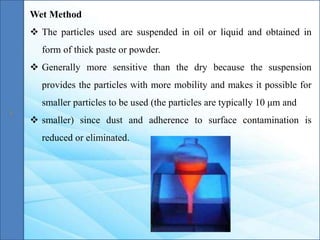
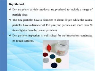
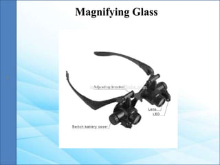
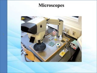
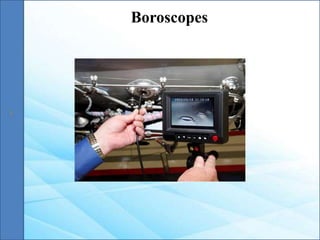
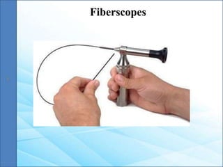
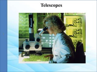
This document discusses visual inspection as a non-destructive testing method. It describes visual inspection techniques including unaided and aided inspection using tools like magnifying mirrors, glasses, microscopes, and boroscopes. The key advantages are that visual inspection is simple, inexpensive, and can detect surface flaws. Limitations include only detecting surface defects and relying on the inspector's skills. The document provides examples of using visual inspection to check for corrosion, cracks, alignment, and leakage.
This document discusses non-destructive testing (NDT) methods, with a focus on visual inspection techniques. It defines NDT as examining materials and components without destroying them to find defects. Several NDT methods are described including visual inspection, liquid penetrant testing, magnetic particle testing, etc. Visual inspection can be unaided or aided using tools like magnifying mirrors, boroscopes, and robotic crawlers. Factors that influence visual testing like surface conditions, environment, and inspector fatigue are also covered. The document provides examples of visual inspection applications and lists advantages and limitations of various NDT methods.
1. The document discusses visual inspection as a non-destructive testing method for detecting discontinuities before they cause major problems.
2. It describes visual inspection using the naked eye as direct unaided visual testing, and using optical aids like magnifying glasses as direct aided visual testing.
3. Factors that can affect visual inspection are discussed, including surface condition, physical conditions, environmental factors, and mental fatigue.
Non-destructive testing or non-destructive testing (NDT) is a wide group of analysis techniques used in science and technology industry to evaluate the properties of a material, component or system without causing damage.
"This ppt also includes some notes in the slide so to see notes go to the view options and select notes page."
This document provides an overview of non-destructive testing (NDT) methods. It begins with an introduction that defines NDT and lists some common applications. It then discusses the objectives and various types of NDT, including visual inspection, liquid penetrant testing, ultrasonic testing, radiography, and eddy current testing. For each type, it provides details on testing principles, procedures, advantages, limitations and applications. The document aims to inform the reader about different NDT techniques and their uses in quality control and material inspection.
This document discusses visual testing (VT) as a non-destructive testing method. It describes VT as examining components visually to identify surface flaws and defects. Both unaided visual inspection with the naked eye and aided inspection using optical devices are discussed. Proper lighting is important for VT. The document outlines factors that affect VT like surface conditions, inspection environment, and human physiological factors.
Visual Inspection is a method in Non-destructive Testing, that relies on the human eye to assess the surface conditions of materials, and structures. Read More!
The document discusses non-destructive testing (NDT) methods. It describes 8 common NDT techniques: visual testing, liquid penetrant testing, magnetic particle testing, radiographic testing, eddy current testing, ultrasonic testing, acoustic emission testing, and thermography. It provides details on visual testing and liquid penetrant testing methods, including their basic principles, advantages, limitations, and applications. Magnetic particle testing is also introduced as a method to detect defects in ferromagnetic materials using magnetic fields and particles.
This document provides information about a seminar report on non-destructive testing (NDT) submitted by Jamshed Alam to fulfill the requirements for a Bachelor of Technology degree in Mechanical Engineering. The report acknowledges the guidance of Mr. Prabhakar Gupta and Mr. Shailendra Kumar Neeraj. It includes an introduction to NDT, common applications of NDT, objectives of NDT, and descriptions of various NDT methods like visual inspection, liquid penetrant testing, ultrasonic testing, and radiography. The document also provides details about equipment used for visual inspection and its applications.
Visual inspection, or visual testing (VT), is one of the most common non-destructive testing methods. It involves an operator visually inspecting a test piece for defects using the naked eye or optical instruments. VT allows for quick quality checks during manufacturing and for products in service. Common defects that can be detected include corrosion, cracks, damage, misalignment, and welding defects. VT is also used to support other NDT methods by performing initial visual inspections. While effective and inexpensive, VT only detects surface defects and optical instruments are needed to identify minute flaws. New technologies like drones, AI, and remote visual systems are enhancing inspection capabilities.
This document provides an introduction to non-destructive testing (NDT). It defines NDT as using noninvasive techniques to inspect materials and components without damaging them. The document outlines six common NDT methods - visual testing, liquid penetrant testing, magnetic particle testing, ultrasonic testing, eddy current testing, and radiography. It provides details on the basic principles, equipment, and applications of each method. The document also discusses the advantages of NDT, its various applications across industries like aviation, oil and gas, and construction, and important terminology used in NDT.
This document provides an overview of non-destructive testing (NDT) techniques. It discusses the objective of NDT to detect defects without damaging products. Three common NDT techniques are described: visual inspection to find surface defects, liquid penetrant testing where a dye reveals surface cracks, and radiography using x-rays to see internal flaws by images on film. The document provides details on the basic procedures and principles for each technique.
Non-destructive testing (NDT) involves various techniques used to evaluate materials, components, or systems without damaging them. Common NDT methods described in the document include visual inspection, liquid penetrant testing, magnetic particle testing, thermography, radiography, eddy current testing, ultrasonic testing, and acoustic emission testing. Each method has advantages and limitations for detecting surface or internal flaws depending on the material and component being tested. NDT plays an important role in quality control and reliability across various industries.
Unit-III Non Destructive Testing (NDT)
Subject Name: OML751 Testing of Materials
Topics: Various NDT tests [Visual inspection, Liquid penetrant test, Magnetic particle test, Thermography test, Radiographic test, Eddy current test, Ultrasonic test, Acoustic emission test]
B.E. Mechanical Engineering
Final Year, VII Semester, Open Elective Subject
[As per Anna University R-2017]
This document provides an overview of non-destructive testing (NDT) methods, focusing on visual inspection. It defines visual inspection as the oldest and most basic NDT method, using only the naked eye to look for flaws. The document distinguishes between unaided visual inspection, using only the eye, and aided visual inspection, which employs optical or mechanical instruments like borescopes, microscopes, calipers and feeler gauges to enhance inspection capabilities. It provides examples of different optical and mechanical aids used to conduct aided visual inspections.
non-destructive techniques used in maintenance engineering it covers a different type of technique like VISUAL.DYE penetrating testing. MAGNETIC particle, ULTRA Sonic testing RADIO GRAPHIC, and in last ndt importance
NDT Versus Mechanical testing, Overview of the Non Destructive Testing Methods for the detection of manufacturing defects as well as material characterisation. Relative merits and limitations, Various physical characteristics of materials and their applications in NDT., Visual inspection – Unaided and aided
Introduction to NDT and Visual Inspection Hareesh K
The document provides an overview of non-destructive testing (NDT) with a focus on visual inspection techniques. It discusses that NDT involves analyzing materials and components without damaging them to check for flaws or issues. Visual inspection is one of the most common NDT methods and can identify surface issues using the human eye or tools like borescopes, microscopes, and cameras. The document outlines different visual inspection tools and techniques for aiding inspection and enhancing perception.
Seminar report on Non Destructive TestingSakshyam Rai
This document provides a summary of non-destructive testing (NDT) methods. It discusses various NDT techniques such as visual inspection, dye penetration testing, magnetic particle inspection, and ultrasonic testing. For each method, it explains the basic principles, testing procedures, advantages, and limitations. The document is a report submitted by a student to their professor on the topic of NDT, as indicated by the title and introduction. It aims to inform the reader about common NDT approaches through detailed descriptions of select techniques.
Article on Dye Penetrant Inspection | Integrated NDE Solution.pdfintegratedndesolutio
Specializing in liquid dye penetrant testing to find surface-breaking faults, Integrated NDE Solution offers professional non-destructive testing services. We use our economical penetrant testing methods—which work on both ferrous and non-ferrous materials—to visible solvent removable, water washable, and post-emulsifiable compounds. You may rely on our highly skilled staff, accredited to ASNT and EN ISO 9712 standards, for accurate and dependable non-destructive testing (NDT) inspection services.
The document discusses the American Welding Society (AWS) and non-destructive testing (NDT). It provides information on ASNT, the leading organization for NDT professionals, and its role in setting standards and qualifications. It also outlines the most common NDT methods including visual, liquid penetrant, magnetic particle, ultrasonic, eddy current, and X-ray testing. Finally, it discusses AWS and their welding certifications, codes, and definition of a welding procedure.
This document provides a summary of dye penetrant inspection (DPI), also known as liquid penetrant inspection (LPI), which is a widely used non-destructive testing method for locating surface-breaking defects in non-porous materials. The summary describes the basic principles and steps of the DPI process, which involves applying a penetrant that soaks into surface defects, removing excess penetrant, and applying a developer that draws the penetrant out of defects to reveal cracks or flaws. The document also briefly discusses the history of DPI, common materials used, advantages and disadvantages, and relevant testing standards.
This document discusses non-destructive testing (NDT) and provides examples of common NDT methods. It describes liquid penetrant testing, magnetic particle testing, radiography, ultrasonic testing, and outlines their advantages and disadvantages. NDT is used across various industries to inspect materials and components during production and in-service to detect flaws without causing damage.
This document provides information about various non-destructive testing (NDT) methods. It discusses visual inspection, liquid penetrant testing, magnetic particle testing, and some common uses of NDT. Liquid penetrant testing uses a liquid dye that is drawn into surface-breaking flaws by capillary action and then revealed using a developer. Magnetic particle testing magnetizes a part and uses iron particles to reveal surface or near surface defects. NDT methods are used for applications like flaw detection, leak detection, and monitoring manufacturing processes without causing damage.
This document discusses various methods of condition monitoring to detect potential equipment failures. It describes 8 types of condition monitoring: 1) temperature measurement, 2) viscosity comparison test, 3) vibration test, 4) stroboscope, 5) leak detection, 6) crack detection, 7) fluorescent penetrate, and 8) handle stethoscope. It provides details on different techniques for each type, including how various sensors measure temperature, methods for detecting leaks and cracks, and how a stroboscope can be used to analyze machine vibrations and detect slipping belts.
This document discusses non-destructive testing (NDT) techniques. It defines defects as any departure from specified material requirements that can reduce service life. Common defects include cracks, surface defects, blow holes, porosity, and slags. Visual inspection and borescopes are described as visual NDT methods. Acoustic emission testing detects cracks and corrosion by measuring ultrasonic pulses emitted during stress testing. Liquid penetrant testing is used to detect issues like corrosion, weld discontinuities, cracks, fractures, leaks, and misalignments.
Non-destructive testing (NDT) refers to a group of analysis techniques used to evaluate materials, components, or systems without causing damage. Common NDT methods include liquid penetrant testing, magnetic particle testing, and ultrasonic testing. Liquid penetrant testing uses a dye that is drawn into surface-breaking flaws by capillary action and visualized. Magnetic particle testing magnetizes a part and uses iron particles to indicate areas of magnetic flux leakage from subsurface flaws. Ultrasonic testing uses high frequency sound waves that reflect off internal flaws and interfaces, with the reflections analyzed to detect and characterize imperfections.
This document provides information on liquid penetrant testing (LPT), including how it works, the process involved, and advantages/disadvantages compared to other non-destructive testing methods. LPT uses penetrant dyes or fluorescent liquids to reveal surface-breaking defects in materials. The process involves cleaning and preparing the surface, applying penetrant, removing excess penetrant, applying developer, and inspecting for indications of flaws under UV or normal light. LPT is fast, sensitive to small flaws, and works for many materials, but only detects surface flaws and requires careful cleaning.
This document discusses various mechanical material testing methods. It provides details on hardness testing methods like Vickers, Brinell, and Rockwell tests. It describes how each test is performed, how the results are calculated to determine the hardness value, and the advantages and limitations of each test. The document also discusses other common mechanical tests like tensile, impact, bend, and fatigue tests and how they are used to determine specific mechanical properties of materials.
This document provides an overview of idea generation and refinement techniques used in design thinking. It discusses methods like brainstorming, sketching, inspiration, themes of thinking, value, inclusion, personification, and visual metaphors that designers use to generate design concepts and ideas. The document is intended to introduce students to various ideation methods and help unleash creativity in resolving design problems.
This document outlines the key stages of design thinking and product life cycles. It discusses:
1) The 5 stages of design thinking: empathize, define, ideate, prototype, and test. This is a human-centered process to generate innovative solutions.
2) The 4 stages of a product's life cycle: introduction, growth, maturity, and decline. This describes the typical lifespan of a product in the market.
3) Design ethics and how designers should consider moral behavior and responsible choices when developing products and solutions.
(1) The document discusses the design and development of prototypes for wall plastering. It describes how wall plastering is commonly used to repair cracks or peeling paint on walls. (2) It provides details on the materials and process used for wall plastering like cement and applying plaster with a trowel. (3) The document then outlines the stages of the design thinking process that will be followed - empathizing to understand user needs, defining problems, ideating solutions, prototyping ideas, and testing prototypes.
This document discusses flow through circular pipes. It presents equations for the velocity profile of fluid flow in a pipe based on viscosity. The velocity is highest in the center and reduces towards the walls according to an equation that is derived. The maximum velocity and flow rate through an elementary ring of the pipe is also defined. Pressure drop over the length of the pipe is mentioned.
This document provides an introduction to fluid mechanics and fluid properties. It discusses:
1) Fluid mechanics is the study of fluids at rest and in motion, and is divided into fluid statics and fluid dynamics (kinematics and kinetics).
2) Key fluid properties include density, specific weight, specific volume, viscosity, compressibility, and surface tension. Equations for calculating these properties are presented.
3) Types of fluids include ideal, real, Newtonian, non-Newtonian, and plastic fluids. Types of flow include steady, unsteady, uniform, non-uniform, compressible, and incompressible flow.
The document discusses the origins and key concepts of Just-in-Time (JIT) and Lean operations. It originated from the Toyota Production System in the 1960s and was later adopted by other automakers. The main goals of JIT are to reduce waste, improve quality, and lower costs through techniques like reducing inventory levels, standardized work flows, visual controls, and continuous improvement. Key benefits include reduced lead times and work-in-process (WIP), higher productivity, and better customer satisfaction.
Computer integrated manufacturing (CIM) incorporates all manufacturing processes including CAD/CAM, business functions, and engineering functions. CIM aims to achieve lower costs, higher quality, and better responsiveness through techniques like group technology, flexible manufacturing systems, and shop floor control using concepts like CONWIP. Group technology groups similar parts into families to improve productivity. Flexible manufacturing systems are reprogrammable systems that can produce different product types automatically using components like machine tools and automated material handling.
Understanding Inductive Bias in Machine LearningSUTEJAS
This presentation explores the concept of inductive bias in machine learning. It explains how algorithms come with built-in assumptions and preferences that guide the learning process. You'll learn about the different types of inductive bias and how they can impact the performance and generalizability of machine learning models.
The presentation also covers the positive and negative aspects of inductive bias, along with strategies for mitigating potential drawbacks. We'll explore examples of how bias manifests in algorithms like neural networks and decision trees.
By understanding inductive bias, you can gain valuable insights into how machine learning models work and make informed decisions when building and deploying them.
ACEP Magazine edition 4th launched on 05.06.2024Rahul
This document provides information about the third edition of the magazine "Sthapatya" published by the Association of Civil Engineers (Practicing) Aurangabad. It includes messages from current and past presidents of ACEP, memories and photos from past ACEP events, information on life time achievement awards given by ACEP, and a technical article on concrete maintenance, repairs and strengthening. The document highlights activities of ACEP and provides a technical educational article for members.
Harnessing WebAssembly for Real-time Stateless Streaming PipelinesChristina Lin
Traditionally, dealing with real-time data pipelines has involved significant overhead, even for straightforward tasks like data transformation or masking. However, in this talk, we’ll venture into the dynamic realm of WebAssembly (WASM) and discover how it can revolutionize the creation of stateless streaming pipelines within a Kafka (Redpanda) broker. These pipelines are adept at managing low-latency, high-data-volume scenarios.
We have compiled the most important slides from each speaker's presentation. This year’s compilation, available for free, captures the key insights and contributions shared during the DfMAy 2024 conference.
A SYSTEMATIC RISK ASSESSMENT APPROACH FOR SECURING THE SMART IRRIGATION SYSTEMSIJNSA Journal
The smart irrigation system represents an innovative approach to optimize water usage in agricultural and landscaping practices. The integration of cutting-edge technologies, including sensors, actuators, and data analysis, empowers this system to provide accurate monitoring and control of irrigation processes by leveraging real-time environmental conditions. The main objective of a smart irrigation system is to optimize water efficiency, minimize expenses, and foster the adoption of sustainable water management methods. This paper conducts a systematic risk assessment by exploring the key components/assets and their functionalities in the smart irrigation system. The crucial role of sensors in gathering data on soil moisture, weather patterns, and plant well-being is emphasized in this system. These sensors enable intelligent decision-making in irrigation scheduling and water distribution, leading to enhanced water efficiency and sustainable water management practices. Actuators enable automated control of irrigation devices, ensuring precise and targeted water delivery to plants. Additionally, the paper addresses the potential threat and vulnerabilities associated with smart irrigation systems. It discusses limitations of the system, such as power constraints and computational capabilities, and calculates the potential security risks. The paper suggests possible risk treatment methods for effective secure system operation. In conclusion, the paper emphasizes the significant benefits of implementing smart irrigation systems, including improved water conservation, increased crop yield, and reduced environmental impact. Additionally, based on the security analysis conducted, the paper recommends the implementation of countermeasures and security approaches to address vulnerabilities and ensure the integrity and reliability of the system. By incorporating these measures, smart irrigation technology can revolutionize water management practices in agriculture, promoting sustainability, resource efficiency, and safeguarding against potential security threats.
Introduction- e - waste – definition - sources of e-waste– hazardous substances in e-waste - effects of e-waste on environment and human health- need for e-waste management– e-waste handling rules - waste minimization techniques for managing e-waste – recycling of e-waste - disposal treatment methods of e- waste – mechanism of extraction of precious metal from leaching solution-global Scenario of E-waste – E-waste in India- case studies.
Embedded machine learning-based road conditions and driving behavior monitoringIJECEIAES
Car accident rates have increased in recent years, resulting in losses in human lives, properties, and other financial costs. An embedded machine learning-based system is developed to address this critical issue. The system can monitor road conditions, detect driving patterns, and identify aggressive driving behaviors. The system is based on neural networks trained on a comprehensive dataset of driving events, driving styles, and road conditions. The system effectively detects potential risks and helps mitigate the frequency and impact of accidents. The primary goal is to ensure the safety of drivers and vehicles. Collecting data involved gathering information on three key road events: normal street and normal drive, speed bumps, circular yellow speed bumps, and three aggressive driving actions: sudden start, sudden stop, and sudden entry. The gathered data is processed and analyzed using a machine learning system designed for limited power and memory devices. The developed system resulted in 91.9% accuracy, 93.6% precision, and 92% recall. The achieved inference time on an Arduino Nano 33 BLE Sense with a 32-bit CPU running at 64 MHz is 34 ms and requires 2.6 kB peak RAM and 139.9 kB program flash memory, making it suitable for resource-constrained embedded systems.
Manufacturing Process of molasses based distillery ppt.pptx
NDT.pptx
1. OML751 TESTING OF MATERIALS
UNIT III – NON DESTRUCTIVE TESTING
Mr. S. Muthu Natarajan M.E., (Ph.D.),
Assistant Professor/Mechanical
Kamaraj College of Engineering and Technology (Autonomous)
Madurai District
Mobile: +91-9566470389
2. Visual inspection, Liquid penetrant test,
Magnetic particle test, Thermography test –
Principles, Techniques, Advantages and
Limitations, Applications. Radiographic test,
Eddy current test, Ultrasonic test, Acoustic
emission- Principles, Techniques, Methods,
Advantages and Limitations, Applications.
Syllabus
3. Visual inspection is the simplest, fastest and most widely used non-
destructive testing method.
Visual inspection is carried out with naked eye(unaided) or using
some optical aids (aided) such as mirrors, magnifying glasses and
microscopes etc.
Visual inspection is defined as the examination of material or
component for conditions of nonconformance using light and the
eyes alone or in conjunction with various aids.
Visual inspection often also involves shaking, listening, feeling and
sometimes even smelling the component being inspected.
Visual Inspection
4. Visual inspection is commonly employed to support other NDT
methods
Other NDT methods require visual intervention to interpret images
obtained while carrying out examinations. At some point, all NDT
methods fall back on visual testing.
For Example, LPT uses dyes that rely on the inspectors ability to
visually identify surface indications.
Digital detectors and computer technology have made it possible to
automate visual inspections. This is known as machine vision
Visual Inspection (Contd…)
5. Visual testing is commonly used
To detect surface characteristics such as surface finish, scratches,
cracks, colour, wear and corrosion
To check alignment of mating surfaces
To check the evidence of leaking
To check internal side defects
Characteristics
6. Advantages
Simple and easy to use
Relatively inexpensive
Testing speed is high
Testing can be performed on components which are in-service
Permanent records are available when latest equipments are used
Almost all materials can be inspected
Limitations
Limited to detection of surface flaws
The test results depend on skill and knowledge of tester
Eye resolution is week
Eye fatigue
Advantages & Disadvantages
7. Classified on the basis of use of aids used
(i) Unaided or direct visual testing
(ii) Aided visual testing
Unaided or direct visual testing
As the name suggests, the unaided visual testing is carried out with
naked eye (without using any optical aids)
The most important instrument in visual inspection is human eye
Classification of Visual Inspection
8. Human eye is the most fascinating and valuable tool in NDT
It has greater precision and accuracy than many of the most
sophisticated cameras. It has unique focusing capabilities and has the
ability to work in conjunction with the human brain so that it can be
trained to find specific details or characteristics in a test specimen.
It has the ability to differentiate and distinguish between colors and
their tones/shades characteristics as well
Human eye is capable of assessing many visual characteristics and
identifying various types of discontinuities
The eye can perform accurate inspections to detect size, shape,
colour, depth, brightness, contrast and texture
Eye
9. As the name suggests, the aided inspection is carried out with the
help of optical aids (such as magnifying glasses, microscopes,
borescopes, fiberscopes) and a variety of other optical imaging and
image enhancement tools.
The optical aids are mainly used for
(i) Magnification of defects which cannot be detected by
unaided visual inspection
(ii) Assisting in the inspection of defects
(iii) areas where not easily accessible to human eye
Aided Visual Inspection
10. The optical aids used for visual inspection are
(i) Magnifying Mirrors (small, angled mirrors)
(ii) Magnifying glasses, eye loupes, multi-lens magnifiers,
measuring magnifiers
(iii) Microscopes(optical and electron)
(iv) Boroscopes
(v) Fiberscopes and videoscopes
(vi) Telescopes
(vii) Periscopes
(viii) Optical comparators
Equipments Used
11. When inspecting areas not easily accessible, a magnifying mirror can
be used
Depending on the test specimen, the mirror can be of any size.
Magnifying Mirrors
Magnifying Glass
A magnifying glass can be used for closer inspection of suspicious
looking areas
It generally consists of a simple lens for lower power magnification
and double or multiple lenses for higher magnification
12. Microscope is a multiple element magnifier for providing very high
magnified image of small object
The simple microscopes consists of a convex lens. The object is
placed between lens and focus length of lens, so that an erect, virtual
and magnified image is formed. The size of the image of an object
depends upon the angle subtended at the eye by the object.(known as
visual or angle)
Microscopes
13. Borescope are optical instrument designed for remote viewing of
objects. They are used to inspect the inside of a narrow tube, bore or
chamber.
Borescopes is a precision optical instrument with built-in
illumination
Borescopes, also called endoscopes or endoprobes consist of superior
optical systems and high intensity light sources.
Some Borescopes provide magnification option, zoom controls.
Because of the variety of applications, Borescopes are manufactured
in rigid, extended, flexible and micro designs.
Boroscopes
14. Modern fiberscope and videoscopes, due to their small size and
flexibility, can provide access to internal areas inaccessible to rigid
borescopes.
Using these, digital images can be captured and processed in real
time. With the aid of laser lights, the area and depth of many surface
defects can also be determined
Fiberscopes and Videoscopes
Telescopes
Telescope is an instrument that collects radiation from a distant
object in order to produce an image of it.
An optical telescope uses visual radiations
The telescopes are used for providing visual examination of the
inaccessible surfaces
15. Optical comparators are the magnifying devices for visual
examination and measurement.
A comparator produces 2D enlarged image of an object on a large
ground-glass screen.
Optical comparators project the image of small parts onto a large
projection screen. The magnified image is then compared against an
optical comparator chart, which is a magnified outline drawing of the
workpiece being gauged
Optical Comparator
16. Inspection of cleaning in machines
Checking for corrosion, erosion and deformities of machine
components
Checking for ruptures, cracks and wear of parts in the equipment.
Monitoring of manometers, pressure and temperatures
Monitoring of oil level, greasing and greasing apparatus.
Monitoring of the operational conditions of systems or machines.
Visual Testing of welds, Pumps, Hydraulic systems, Belt Pulley,
Forging Discontinuities
Applications of Visual Inspection
24. This method is used to reveal surface discontinuities by bleed-out of
a colored or fluorescent dye from the flaw.
The technique is based on the ability of a liquid to be drawn into a
"clean" surface discontinuity by capillary action
After a period of time called the "dwell time", excess surface
penetrant is removed and a developer applied. This acts as a blotter
that draws the penetrant from the discontinuity to reveal its
presence.
Liquid Penetrant Testing
25. Liquid penetrant testing is one of the most widely used NDT
methods. Its popularity can be attributed to two main factors: its
relative ease of use and its flexibility.
It can be used to inspect almost any material provided that its surface
is not extremely rough or porous.
Materials that are commonly inspected using this method include;
metals, glass, many ceramic materials, rubber and plastics
However, liquid penetrant testing can only be used to inspect for
flaws that break the surface of the sample (such as surface cracks,
porosity, laps, seams, lack of fusion, etc.).
26. Steps of Liquid Penetrant Testing
The exact procedure for liquid penetrant testing can vary from case
to case depending on several factors such as,
the penetrant system being used,
the size and material of the component being inspected,
the type of discontinuities being expected in the component
the condition and environment under which the inspection is
performed.
General Steps Followed in Liquid Penetrant Testing Method,
1. Surface Preparation 2. Penetrant Application
3. Penetrant Dwell 4. Excess Penetrant Removal
5. Developer Application 6. Indication Development
7. Inspection 8. Clean Surface
27. Surface Preparation
One of the most critical steps of a liquid penetrant testing is the
surface preparation.
The surface must be free of oil, grease, water, or other contaminants
that may prevent penetrant from entering flaws.
The sample may also require etching if mechanical operations such
as machining, sanding, or grit blasting have been performed.
These and other mechanical operations can smear metal over the
flaw opening and prevent the penetrant from entering.
Penetrant Application
Once the surface has been thoroughly cleaned and dried, the
penetrant material is applied by spraying, brushing, or immersing
the part in a penetrant bath.
28. Penetrant Dwell
The penetrant is left on the surface for a sufficient time to allow as
much penetrant as possible to be drawn or to seep into a defect.
Penetrant dwell time is the total time that the penetrant is in contact
with the part surface. Dwell times are usually recommended by the
penetrant producers or required by the specification being followed.
The times vary depending on the application, penetrant materials
used, the material, the form of the material being inspected, and the
type of discontinuity being inspected for.
Minimum dwell times typically range from 5 to 60 minutes.
Generally, there is no harm in using a longer penetrant dwell time as
long as the penetrant is not allowed to dry.
29. Excess Penetrant Removal
This is the most delicate step of the inspection procedure because
the excess penetrant must be removed from the surface of the
sample while removing as little penetrant as possible from defects.
Depending on the penetrant system used, this step may involve
cleaning with a solvent, direct rinsing with water, or first treating the
part with an emulsifier and then rinsing with water.
30. Developer Application
A thin layer of developer is then applied to the sample to draw
penetrant trapped in flaws back to the surface where it will be
visible. Developers come in a variety of forms that may be applied
by dusting (dry powders), dipping, or spraying (wet developers).
Indication Development
The developer is allowed to stand on the part surface for a period of
time sufficient to permit the extraction of the trapped penetrant out
of any surface flaws.
This development time is usually a minimum of 10 minutes.
Significantly longer times may be necessary for tight cracks.
31. Inspection
Inspection is then performed under appropriate lighting to detect
indications from any flaws which may be present.
Clean Surface
The final step in the process is to thoroughly clean the part surface
to remove the developer from the parts that were found to be
acceptable.
32. Advantages & Disadvantages
PROS CONS
High sensitivity (small discontinuities can
be detected).
Only surface breaking defects can be
detected.
Few material limitations (metallic and
nonmetallic, magnetic and nonmagnetic,
and conductive and nonconductive
materials may be inspected)
Only materials with a relatively non-
porous surface can be inspected
Rapid inspection of large areas and
volumes
Pre-cleaning is critical since contaminants
can mask defects
Suitable for parts with complex shapes
Metal smearing from machining,
grinding, and grit or vapor blasting must
be removed
Indications are produced directly on the
surface of the part and constitute a visual
representation of the flaw
The inspector must have direct access to
the surface being inspected
Portable (materials are available in
aerosol spray cans)
Surface finish and roughness can affect
inspection sensitivity
Low cost (materials and associated
equipment are relatively inexpensive)
Multiple process operations must be
performed and controlled
33. Penetrants are carefully formulated to produce the level of sensitivity
desired by the inspector. The penetrant must possess a number of
important characteristics,
Spread easily over the surface of the material being inspected to
provide complete and even coverage
Be drawn into surface breaking defects by capillary action.
Remain in the defect but remove easily from the surface of the part.
Remain fluid so it can be drawn back to the surface of the part
through the drying and developing steps.
Be highly visible or fluoresce brightly to produce easy to see
indications.
Not be harmful to the material being tested or the inspector.
Penetrants
34. Types of Penetrants
Penetrant materials come in two basic types:
Type 1 - Fluorescent Penetrants
They contain a dye or several dyes that fluoresce when exposed
to ultraviolet radiation
Type 2 - Visible Penetrants
They contain a red dye that provides high contrast against the
white developer background
Fluorescent penetrant systems are more sensitive than visible
penetrant systems because the eye is drawn to the glow of the
fluorescing indication. However, visible penetrants do not require a
darkened area and an ultraviolet light in order to make an inspection.
35. Penetrants are then classified by the method used to remove the excess
penetrant from the part. The four methods are:
Method A - Water Washable:
Penetrants can be removed from the part by rinsing with water
alone. These penetrants contain an emulsifying agent (detergent) that
makes it possible to wash the penetrant from the part surface with water
alone. Water washable penetrants are sometimes referred to as self-
emulsifying systems.
Method B – Post - Emulsifiable, Lipophilic:
The penetrant is oil soluble and interacts with the oil-based
emulsifier to make removal possible.
Types of Penetrants (Contd…)
36. Method C - Solvent Removable:
They require the use of a solvent to remove the penetrant from
the part.
Method D - Post-Emulsifiable, Hydrophilic:
They use an emulsifier that is a water soluble detergent which
lifts the excess penetrant from the surface of the part with a water
wash.
37. Penetrants are then classified based on the strength or detectability of
the indication that is produced for a number of very small and tight
fatigue cracks. The five sensitivity levels are:
Level ½ - Ultra Low Sensitivity
Level 1 - Low Sensitivity
Level 2 - Medium Sensitivity
Level 3 - High Sensitivity
Level 4 - Ultra-High Sensitivity
The procedure for classifying penetrants into one of the five
sensitivity levels uses specimens with small surface fatigue cracks. The
brightness of the indication produced is measured using a photometer.
Types of Penetrants (Contd…)
38. The role of the developer is to pull the trapped penetrant material
out of defects and spread it out on the surface of the part so it can
be seen by an inspector.
Developers used with visible penetrants create a white background
so there is a greater degree of contrast between the indication and
the surrounding background.
On the other hand, developers used with fluorescent penetrants both
reflect and refract the incident ultraviolet light, allowing more of it
to interact with the penetrant, causing more efficient fluorescence.
Developers
39. This test is used to detect the hot crack which can happen during
solidification process of deposited weld metal, and it might happen
in weld metal or in weld heat affected zone. The surface lack of
fusion also can be identified by this test.
The surface porosity is a common surface defect that can be found
visually and more accurately by dye penetration test. The
acceptance criteria for the liquid penetrant test for welding have
been addressed on the ASME Code Section VIII Div 1 Mandatory
appendix 8.
LPT Application on Welding
40. The casting surface porosity, surface shrinkage, hot tear and cold
shut can be detected by liquid penetrant inspection. The acceptance
criteria have been addressed in ASME Section VIII Div 1.
Mandatory Appendix 7.
LPT Application on Casting
LPT Application on Forging
The forging surface detects are Laps and Bursts which both can
easily be identified by performing a liquid penetrant test.
41. Magnetic Particle Testing - Introduction
1 • Ferromagnetic Materials
2 • Diamagnetic Materials
3 • Paramagnetic Materials
Types of Magnetic Materials
Those materials which can be strongly magnetized and are suitable
for MPT (Magnetic Particle Testing).
Example: Iron, Nickel, Cobalt alloys, etc.
These materials are not magnetized in direct proportion to the
applied magnetizing force.
Beyond the saturation point, part cannot be further magnetized.
Ferromagnetic Materials
42. Diamagnetic Materials
Paramagnetic Materials
Those materials which are feebly repelled by strong magnet.
In diamagnetic materials all the electrons are paired so there is no
permanent net magnetic moment per atom.
Example: Most elements in the periodic table, including copper,
silver, and gold, are diamagnetic.
Those materials which can be magnetized but weakly.
Example: Oxygen, magnesium, molybdenum, and lithium.
43. Methods of Generating Magnetic Fields
1
• Direct Magnetization
2
• Indirect Magnetization
Direct Magnetization
With direct magnetization, current is passed directly through the
component. The flow of current causes a circular magnetic field to
form in and around the conductor.
When using the direct magnetization method, care must be taken to
ensure that good electrical contact is established and maintained
between the test equipment and the test component to avoid damage
of the component.
44. Indirect Magnetization
Indirect magnetization is accomplished by using a strong external
magnetic field to establish a magnetic field within the component.
Demagnetization
After conducting a magnetic particle inspection, it is usually
necessary to demagnetize the component.
Removal of a field may be accomplished in several ways
By heating the material above its curie temperature (for instance, the
curie temperature for a low carbon steel is 770°C).
When steel is heated above its curie temperature then it is cooled
back down, the orientation of the magnetic domains of the individual
grains will become randomized again and thus the component will
contain no residual magnetic field.
45. Magnetic Particle Testing
Magnetic particle testing is one of the most widely utilized NDT
methods since it is fast and relatively easy to apply and part surface
preparation is not as critical as it is for some other methods.
This method uses magnetic fields and small magnetic particles (i.e.
iron) to detect flaws in components.
The component being inspected must be made of a ferromagnetic
material (a materials that can be magnetized) such as iron, nickel,
cobalt, or some of their alloys.
Underwater inspection is another area where magnetic particle
inspection may be used to test items such as offshore structures and
underwater pipelines
46. Basic Principle
It can be considered as a combination of two nondestructive testing
methods: magnetic flux leakage testing and visual testing.
For the case of a bar magnet, the magnetic field is in and around the
magnet. Any place that a magnetic line of force exits or enters the
magnet is called a “pole” (magnetic lines of force exit the magnet
from north pole and enter from the south pole).
When a bar magnet is broken in the center of its length, two
complete bar magnets with magnetic poles on each end of each piece
will result.
If the magnet is just cracked but not broken completely in two, a
north and south pole will form at each edge of the crack
47. The magnetic field exits the north pole and reenters at the south pole.
The magnetic field spreads out when it encounters the small air gap
created by the crack because the air cannot support as much magnetic
field per unit volume as the magnet can.
When the field spreads out, it appears to leak out of the material and,
thus is called a flux leakage field.
If iron particles are sprinkled on a cracked magnet, the particles will
be attracted to and cluster not only at the poles at the ends of the
magnet, but also at the poles at the edges of the crack. This cluster of
particles is much easier to see than the actual crack and this is the
basis for magnetic particle inspection
48.
49. General Steps Followed in Magnetic Particle Testing Method,
Surface Preparation
Initial Demagnetization
Magnetization
Application of Magnetic Particles
Viewing
Marking of Defects
Demagnetization
Removal of Ink from Components
50. Surface Preparation
Loose rust & scale removed from part in order to prevent the
contamination of ink.
The paint should be removed locally to provide adequate contact
areas for current flow.
Initial Demagnetization
Components which have been machined on magnetic chucks or
handled near the magnetic field , has some residual magnetisms
So for avoiding false indication always demagnetize the component
before testing.
Magnetization
Direct or indirect method of magnetization can be used
51. Application of Magnetic Particles
The metal used for the particles has high magnetic permeability and
low retentivity.
High magnetic permeability is important because it makes the
particles attract easily to small magnetic leakage fields from
discontinuities, such as flaws.
Low retentivity is important because the particles themselves never
become strongly magnetized so they do not stick to each other or the
surface of the part
On the basis of carrying agent, it is of two types,
1
• Wet Method
2
• Dry Method
52. Wet Method
The particles used are suspended in oil or liquid and obtained in
form of thick paste or powder.
Generally more sensitive than the dry because the suspension
provides the particles with more mobility and makes it possible for
smaller particles to be used (the particles are typically 10 μm and
smaller) since dust and adherence to surface contamination is
reduced or eliminated.
53. Dry Method
Dry magnetic particle products are produced to include a range of
particle sizes.
The fine particles have a diameter of about 50 μm while the course
particles have a diameter of 150 μm (fine particles are more than 20
times lighter than the coarse particles).
Dry particle inspection is well suited for the inspections conducted
on rough surfaces.
54. Viewing
Magnetic Particles Source of Illumination
Black or Red Paste or Powder Day Light
Fluroscent Paste or Powders Black Light
Marking of Defects
All indication should be marked after allowing the magnetic
particles (ink) to drain.
Demagnetization
Demagnetization can be done by heating the component above its
curie temperature
Removal of Ink from the components
Manual Removal by cleaning the surface of the component