Downloaded 87 times


![Router(config)#router <protocol> [<option>]
Router(config)#router rip
Router(config)#router eigrp 10
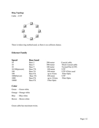
Configuring Password
There are five types of password available in a router
(1) Console Password
router#configure terminal
router(config)#line console 0
router(config-line)#password <word>
router(config-line)#login
router(config-line)#exit
to erase password do all steps with no command.
(2) Vty Password
router>enable
router#configure terminal
router(config)#line vty 0 4
router(config-line)#password <word>
router(config-line)#login
router(config-line)#exit
(3) Auxiliary Password
router#configure terminal
router(config)#line Aux 0
router(config-line)#password <word>
router(config-line)#login
router(config-line)#exit
(4) Enable Password
router>enable
router#configure terminal
router(config)#enable password <word>
router(config)#exit
(5) Enable Secret Password
Enable Password is the clear text password.
Router>enable
Router#configure terminal
Router(config)#enable secret <word>
Router(config)#exit
Page | 18](https://image.slidesharecdn.com/natreport1-130418034707-phpapp01/85/Nat-report-1-18-320.jpg)


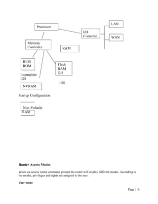
![IP Extended ACL (Numbered)
Extended ACL are advanced ACL. ACL, which can control traffic flow on the basis of five
different parameters that are: -
(i) Source address
(ii) Destination address
(iii) Source port
(iv) Destination port
(v) Protocol (layer 3/layer 4)
The syntax to create Extended ACL
Router#conf ter
Router(config)#access-list <no> <deny|permit> <protocol> <source> [<s.port>]
<destination> [<d.port>]
router(config)#exit
To display ACL
Router#show access-lists or
Router#show access-list <no>
To display ACL applied on interface
Router#show ip interface
Router#show ip interface <type> <no>
Router#show ip interface Ethernet 0
Time-Based ACLs
In this you can specify a certain time of day and week and then identity that particular period by
giving it a name referenced by a task. The reference function will fall under whatever time
constraints you have dictated. The time period is based upon the router’s clock, but it is highly
recommended that using it in conjunction with Network Time Protocol (NTP) synchronization.
Router#conf ter
Router(config)#time-range no-http
Router(config-time-range)#periodic <Wednesday|weekdays|weekend> 06:00 to 12:00
Router(config-time-range)#exit
Router(config)#time-range tcp-yes
Router(config-time-range)#periodic weekend 06:00 to 12:00
Page | 38](https://image.slidesharecdn.com/natreport1-130418034707-phpapp01/85/Nat-report-1-38-320.jpg)


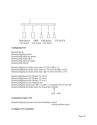


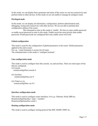
![ORG1(config)#ip nat inside source static tcp 10.0.0.2 80 200.10.10.17 80
In our organisation our clients want to access internet so we will configure
dynamic nat with overload for clients.
ORG1(config)#access-list 20 permit any
ORG1(config)#ip nat pool netmax 200.10.10.18 200.10.10.18 netmask
255.255.255.240
ORG1(config)#ip nat inside source list 20 pool netmax overload
ORG1(config)#exit
ORG1#wr
Building configuration...
[OK]
ORG1#
SWITCH
Page | 47](https://image.slidesharecdn.com/natreport1-130418034707-phpapp01/85/Nat-report-1-47-320.jpg)


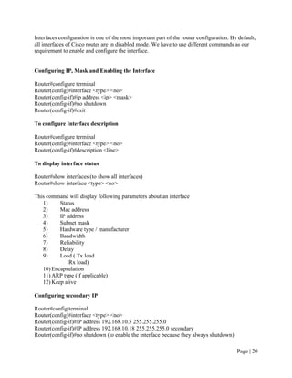
![ORG2#wr
Building configuration...
[OK]
ORG2#
SWITCH
Switch>en
Switch#vlan database
% Warning: It is recommended to configure VLAN from config mode,
as VLAN database mode is being deprecated. Please consult user
documentation for configuring VTP/VLAN in config mode.
Switch(vlan)#vlan 2 name server
VLAN 2 added:
Name: server
Switch(vlan)#vlan 3 name clients
VLAN 3 added:
Name: clients
Switch(vlan)#exit
APPLY completed.
Exiting....
Switch#config t
Enter configuration commands, one per line. End with CNTL/Z.
Switch(config)#int f0/1
Switch(config-if)#switchport access vlan 2
Switch(config-if)#exit
Switch(config)#int range f0/2 - 3
Switch(config-if-range)#switchport access vlan 3
Switch(config-if-range)#exit
Switch(config)#int f0/24
Switch(config-if)#switchport mode trunk
Switch(config-if)#exit
Switch(config)#exit
Switch#wr
Page | 50](https://image.slidesharecdn.com/natreport1-130418034707-phpapp01/85/Nat-report-1-50-320.jpg)
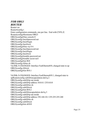
![ORG3(config-if)#ip nat outside
ORG3(config-if)#clock rate 64000
ORG3(config-if)#ip address 200.10.10.13 255.255.255.252
ORG3(config-if)#no sh
%LINK-5-CHANGED: Interface Serial0/0/0, changed state to down
ORG3(config-if)#exit
ORG3(config)#ip route 0.0.0.0 0.0.0.0 serial 0/0/0
ORG3(config)#ip nat inside source static 10.0.0.2 200.10.10.50
ORG3(config)#access-list 20 permit any
ORG3(config)#ip nat pool netmax 200.10.10.51 200.10.10.51 netmask
255.255.255.240
ORG3(config)#ip nat inside source list 20 pool netmax overload
ORG3(config)#exit
%SYS-5-CONFIG_I: Configured from console by console
ORG3#wr
Building configuration...
[OK]
ORG3#
SWITCH
Switch>en
Switch#vlan database
% Warning: It is recommended to configure VLAN from config mode,
as VLAN database mode is being deprecated. Please consult user
documentation for configuring VTP/VLAN in config mode.
Switch(vlan)#vlan 2 name server
VLAN 2 added:
Page | 52](https://image.slidesharecdn.com/natreport1-130418034707-phpapp01/85/Nat-report-1-52-320.jpg)


The document provides information about Netmax Technologies, a company that provides network support, training, and embedded systems development. It discusses [1] Netmax's areas of expertise including network solutions, courses offered, and client list, [2] the team of certified professionals employed, and [3] an introduction to the CCNA training program conducted at Netmax.