Temposonic
•
1 like•1,900 views

This document provides specifications for Temposonics R Series position sensors that use a Synchronous Serial Interface (SSI) for output. Key details include: - SSI is a serial interface that uses a clock pulse train from a controller to transmit 24- or 25-bit position data from the sensor one bit at a time. - Temposonics R Series sensors offer modular construction and non-contacting magnetostrictive technology in either a rod style (Model RH) or profile style (Model RP) housing. - Specifications include resolutions up to 2 microns, operating temperatures from -40°C to 105°C, IP65/IP67 sealing, and measuring ranges from 25

More Related Content
What's hot
What's hot (20)
Similar to Temposonic
Similar to Temposonic (20)
More from José Manuel Valdez
More from José Manuel Valdez (7)
Temposonic
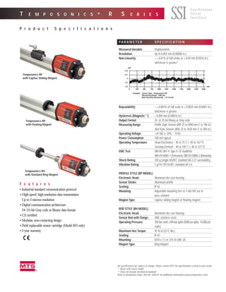
- 1. All specifications are subject to change. Please contact MTS for specifications critical to your needs. * Varies with sensor model ** Does not include mechanical backlash Refer to Installation Guide, Part No. 550574, for additional information (www.temposonics.com). T E M P O S O N I C S ® R S E R I E S P r o d u c t S p e c i f i c a t i o n s SSI F e a t u r e s • Industrial standard communication protocol • High-speed, high-resolution data transmission Up to 2 micron resolution • Digital communication architecture 24-/25-bit Gray code or Binary data format • CE certified • Modular, non-contacting design • Field replaceable sensor cartridge (Model RH only) • 2-year warranty S y n c h r o n o u s S e r i a l I n t e r f a c e m P A R A M E T E R S P E C I F I C A T I O N Measured Variable: Displacement Resolution: Up to 0.002 mm (0.00008 in.) Non-Linearity: < ± 0.01% of full stroke or ± 0.04 mm (0.0016 in.), whichever is greater* Repeatability: < ± 0.001% of full scale or ± 0.0025 mm (0.0001 in.), whichever is greater Hysteresis (Magnetic**): < 0.004 mm (0.00016 in.) Output Format: 24- or 25-bit Binary or Gray code Measuring Range: Profile Style Sensors (RP): 25 to 5000 mm (1 to 196 in.) Rod Style Sensors (RH): 25 to 7620 mm (1 to 300 in.) Operating Voltage: +24 Vdc (+ 20%, - 15%) Power Consumption: 100 mA typical Operating Temperature: Head Electronics: - 40 to 75°C (- 40 to 167°F) Sensing Element: - 40 to 105°C (- 40 to 221°F) EMC Test: DIN IEC 801-4, Type 4, CE Qualified; DIN EN 50081-1 (Emissions), DIN EN 50082-2 (Immunity) Shock Rating: 100 g (single hit)/IEC standard 68-2-27 survivability Vibration Rating: 5 g/10-150 Hz/IEC standard 68-2-6 PROFILE STYLE (RP MODEL) Electronic Head: Aluminum die-cast housing Sensor Stroke: Aluminum profile Sealing: IP 65 Mounting: Adjustable mounting feet or T-slot M5 nut in base channel Magnet Type: Captive sliding magnet or floating magnet ROD STYLE (RH MODEL) Electronic Head: Aluminum die-cast housing Sensor Rod with Flange: 304L stainless steel Operating Pressure: 350 bar static, 690 bar spike (5000 psi spike; 10,000 psi static) Maximum Hex Torque: 45 N-m (33 ft.-lbs.) Sealing: IP 67 Mounting: M18 x 1.5 or 3/4-16 UNF-3A Magnet Type: Ring Magnet + 0.2 + 0.1 0 - 0.1 - 0.2 mm 0 250 500 750 1000 1250 1500 1750 2000 2250 2500 mm Example: Sensor Type: Temposonics RP Measuring Range: 2500 mm Non-linearity (measured): ± 0.116 mm Temposonics RH with Standard Ring Magnet Temposonics RP with Floating Magnet Temposonics RP with Captive Sliding Magnet
- 2. T E M P O S O N I C S R S E R I E S / S S I O U T P U T A D V A N T A G E S • Noise immunity • Cost effective data transfer • Data transmission rate is adjustable and independent of length and resolution • Effective in closed-loop controls; both synchronous and asynchro- nous modes • Transmission over long distances (due to selectable baud rate) FUNCTION Parallel/Serial DataShiftRegister SSIInterface PositionInformation 25-or24-bitBinary orGraycode The diagram, right, illustrates the function of Temposonics R Series position sensors with Serial Synchronous Interface (SSI). The position of a magnet mounted on a machine is precisely determined by a time-based method (i.e., magne- tostriction). The displacement value is provided in a 24- or 25-bit Binary or Gray code data stream and trans- mitted to a controller via SSI. Update frequencies are available up to 7500 measurements per second (length dependent) in asynchronous mode; and 1000 measurements per second in synchronous mode (up to 82 inches). Also, displacement outputs are absolute which means that position information is immediately available upon recovery from power loss. Temposonics R Series position sen- sors are available with a widely accepted controller interface: Synchronous Serial Interface (SSI). Position data from the sensor is encoded in a 24- or 25-bit Binary or Gray code format and transmitted at very high speed via a serial type interface. SSI output provides effective syn- chronization in a closed-loop control system. A clock pulse train from a controller is used to gate out sensor data. Temposonics R Series Sensors offer modular construction and non- contacting magnetostrictive technol- ogy. Two application housings are available: rod style (Model RH) and profile style (Model RP). With the RH sensors, the sensor cartridge (for sen- sor lengths up to 72 inches) can be quickly replaced in the field without removing the application housing (see page 4). Sensor w/SSI - Block Diagram DEFINITIONS: Synchronous Mode: A synchronous pulse from the control system starts the measuring time of the sensor, the measured result is available before the next synchronizing pulse is generated. Asynchronous Mode: SSI takes measurements at its fastest internal interrogation rate (length dependent) and provides information upon request. TEMPOSONICS R SERIES SENSORS WITH SSI OUTPUT 2 NOTE: If controller/interface does not specify synchronous mode, use sensor in asynchronous mode.
- 3. SSI INTERFACE - SENSOR SSI INTERFACE - CONTROLLER + 24 Vdc Ground Clock (+) Clock (-) Data (+) Data (-) 6N137 Opto-Coupler 75174 Output Stage 91Ω 91Ω LED 100Ω 100Ω 2 V 7 mA 22 pF 22 pF Loop Out + Loop Out - MSB LSB Clock (+) Data (+) Clock Interval 25 µs minimum dwell time Clock (+) Clock Pulse Train Clock Pulse Train SSI INTERFACE SSI is a widely used serial interface between an absolute position sensor and a controller. SSI uses a clock pulse train from a controller to initiate a gated out- put from the sensor. A clock pulse train from a controller is used to gate out sensor data: one bit of position data is transmitted to the con- troller per one clock pulse received by the sensor. The absolute position data is con- tinually updated by the sensor and con- verted by the shift register into serial information. Between each clock pulse train there is a minimum dwell of 25 µs during which data is moved into the reg- ister. The data is then shifted out when the sensor receives a pulse train from the controller. When the least significant bit (LSB) goes HIGH and the minimum dwell time has elapsed, new data is avail- able to read. Refer to the diagrams, right. SSI Block Diagram SSI Timing Diagram Sequential Measurements of SSI Timing Baud Rates for Data Transmission Baud Rate 1.5 MBd < 400 kBd < 300 kBd < 200 kBd < 100 kBd Cable Length (ft.) < 10 < 160 < 320 < 650 < 1300 3 For Example: For 25-bit output, the timing clock must have 26 pulses. T E M P O S O N I C S R S E R I E S / S S I O U T P U T
- 4. D I M E N S I O N S / T E M P O S O N I C S R H O-ring Magnet Non-ferrous Spacer (Part No.: 400633) Chamfered Rod Bushing (Customer provided, optional) Threads (3/4-16 UNF-3A or M18 x 1.5 metric threads) Null (as specified) Standard: 50.8 mm (2.0 in.) (Stroke dependent - refer to dimension drawings) Stroke Length Piston Head & Rod Assembly 12.7 mm (0.5 in.) Bore Sensor Rod 10.0 mm (0.394 in.) dia. Raised-Face Flange Hex: 44.5 mm (1.75 in.) across flats, designed to SAE J1926 specifications OR Flat-Faced Flange Hex: 44.5 mm (1.75 in.) across flats Dead Zone CYLINDER INSTALLATION The rod style Temposonics R Series posi- tion sensors (Model RH) are designed for installation into hydraulic cylinders. The sensor’s high-pressure, stainless steel tube installs into a 1/2 inch bore in the piston head and rod assembly as illustrated (right). The illustration above represents a typical installation. Some installation requirements may be application specific. ROD-STYLE (Model RH) The Temposonics R Series rod-style appli- cation housing (Model RH) offers modu- lar construction, flexible mounting con- figurations, and easy installation. It is designed for internal mounting in appli- cations where high-pressure conditions exist (5000 psi continuous, 10,000 psi spike) such as hydraulic cylinders. Temposonics RH may also be mounted externally in many applications. In addition, the RH housing offers the ability to quickly and easily replace the sensor cartridge in the field (up to 72 inches). 64.3 mm (2.53 in.) for strokes ≤ 3500 mm (137.8 in.) 74.3 mm (2.92 in.) for strokes > 3500 mm (137.8 in.) 9/64-in. Socket Head Cap Screw Raised Face 2.5 mm (0.10 in.) 53.0 mm (2.1 in.) Stroke Length External Magnet (Stroke dependent - refer to chart below) 10.0 mm dia. (0.394 in.) O-Ring Thread, 3/4-16 UNF-3A (US Std.) or M18 x 1.5 (metric) 25.4 mm (1.00 in.) Raised-Face Flange Hex: 44.5 mm (1.75 in.) across flats, designed to SAE J1926 specifications Flat-Faced Flange Hex: 44.5 mm (1.75 in.) across flats 9.7 mm (0.380 in.) Dead Zone Null 50.8 mm (2.0 in.) Null Zone 50.8 mm (2.00 in.) Stroke-dependent Dead Zones Stroke Length Dead Zone 25 - 5000 mm (1 - 197 in.) 63.5 mm (2.5 in.) 5005 - 7620 mm (197.1 - 300 in.) 66 mm (2.6 in) 4 70 mm (2.75 in.) 101.6 mm (4.00 in.) D70 Connector w/Straight Exit D7 Mating Connector D70 Connector w/90° D7 Mating Connector 60 mm (2.36 in.) 54 mm (2.16 in.) P Integral Cable
- 5. D I M E N S I O N S / T E M P O S O N I C S R P Captive Sliding Magnet 18° rotation 12 mm (0.47 in.) Null-positionBall jointed arm, M5 thread Mounting Foot Electronics Housing Stroke Length 25 to 5000 mm (1 to 196 in.) Dead Zone 66 mm (2.6 in.) 28 mm (1.10 in.) 44 mm (1.73 in.) 64.3 mm (2.53 in.) for strokes ≤ 3500 mm (137.8 in.) 74.3 mm (2.92 in.) for strokes > 3500 mm (137.8 in.) 36 mm (1.42 in.) Captive Sliding Magnet 45 mm (1.77 in.) 52 mm (2.05 in.) Ball jointed arm, M5 thread 12 mm (0.47 in.) Null-position Captive Sliding Magnet (Style V) 9.1 mm (0.36 in.) 1.9 mm (0.075 in.) 68 mm (2.68 in) 35.5 mm (1.40 in.) 36 mm (1.42 in.) 45 mm (1.77 in.) 44 mm (1.73 in.) 50 mm (1.97 in.) 2 places PROFILE-STYLE (Model RP) Temposonics RP profile style position sensors offer modular construction, flexible mounting configurations, and easy installation. A choice of two magnet mounting configurations are available with the profile housing: captive sliding magnet or floating magnet. Temposonics RP sensors are effective in applications where space is an issue and in environments where there are high levels of dust and conta- mination. In addition, Temposonics RP sensors are designed for external mounting on machines and can be configured with a variety of connector options. Non-magnetic Mounting Support and Screws T-slot Nut, M5 screw Dead Zone 44 mm (1.73 in.) Stroke Length 25 - 5000 mm (1 to 196 in.) 66 mm (2.6 in.) 28 mm (1.10 in.) Floating Magnet 64.3mm(2.53in.) forstrokes ≤3500mm(137.8in.) 74.3mm(2.92in.) forstrokes >3500mm(137.8in.) 28mm (1.10in.) Null-position Floating Magnet Style M) Gap between magnet and top of profile extrusion to be approx. 3 mm (0.12 in.) 35.5 mm (1.40 in.) 44 mm (1.73 in.) 45 mm (1.77 in.) Floating Magnet (Style M) T-slot Nut, M5 Thread (optional,soldseparatley) 5 mm CAPTIVE SLIDING MAGNET FLOATING MAGNET Style V Magnet Style S Magnet Style M Magnet Captive Sliding Magnet, Style V, End View (Shown with standard mounting feet) Floating Magnet, End View (Shown with optional T-slot mounting) 5 NOTE: Temposonics RP Sensors include two mounting feet (Part No. 400802) for sensors up to 1250 mm (50 in.). One additional mounting foot is included for every additional 500 mm (20 in.). NOTE: Cable and mating connector dimensions same as shown on page 4.
- 6. W I R I N G CABLE CONNECTORS (Field-installable D7 Female): Mates with Sensor Integral Connector 6 D7 Straight-exit Connector Part No. 560701 SENSOR INTEGRAL CONNECTOR (D7 Male): (As Viewed from End of Sensor) D7 90º Connector Part No. 560779 37 mm (1.5 in.) 54 mm (2.1 in.) 18 mm (0.7 in.) 58 mm (2.3 in.) 18 mm (0.7 in.) Pin No. Wire Color Function 1 Gray (-) Data 2 Pink (+) Data 3 Yellow (+) Clock 4 Green (-) Clock 5 Brown or Red + 24 Vdc, Customer Supplied 6 White DC Ground 7 Blue No Connection* * Extension cables using the standard cable (Styles DS and DT) do not have a 7th wire. PINOUT / WIRE COLOR CODE (Integral or Extension Cable) 31 76 54 2 NOTE: Appropriate grounding of cable shield is required at the controller end.
- 7. W I R I N G MAGNETS 18° rotation 24 mm (0.95 in.) 22 mm (0.87 in.) 14 mm (0.55 in.) 9 mm (0.35 in.) 40 mm (1.58 in.) Ball jointed arm, M5 thread Rotation: Vertical: ±18° Horizontal: 360° 24 mm (0.95 in.) 37 mm (1.46 in.) 14 mm (0.55 in.) 40 mm (1.58 in.) 35 mm (1.38 in.) Ball jointed arm, M5 thread 140˚ Ø 13.5 mm (0.53 in.) 120˚ 25.5 mm (1.0 in.) 2 Holes each 3.9 mm dia. (0.15 in.) on 23.9 mm dia. (0.94 in.) Captive Sliding Magnet, Style V Part No. 252111-1 Captive Sliding Magnet, Style S Part No. 252110-1 Floating Magnet (May be used with Temposonics RH and RP) Part No. 251416 Magnets must be ordered separately with Temposonics RH sensors. The standard ring magnet (Part No. 201542) is suitable for most applications. Magnets are included with the order of Temposonics RP sensors. Temposonics RP can be configured with one of two magnet configurations: captive sliding magnet or floating magnet. There are two styles of captive sliding magnet, and one style of floating magnet. 4 Holes each 3.9 mm dia. (0.15 in.) 90º apart on 23.9 mm dia. (0.94 in.) ID: 13.5 mm (0.53 in.) OD: 32.8 mm (1.29 in.) Thickness: 7.9 mm (0.312 in. ID: 13.5 mm (0.53 in.) OD: 32.8 mm (1.29 in.) Thickness: 7.9 mm (0.312 in.) 7 Magnet Spacer Part No. 400633 Standard Ring Magnet Part No. 201542 ID: 13.5 mm (0.53 in.) OD: 25.4 mm (1.0 in.) Thickness: 7.9 mm (0.312 in.) (For use with strokes ≤ 3050 mm or 120 in.) Ring Magnet Part No. 400533 4 Holes each 3.9 mm dia. (0.15 in.) 90º apart on 23.9 mm dia. (0.94 in.) ID: 14.3 mm (0.56 in.) OD: 31.8 mm (1.25 in.) Thickness: 3.2 mm (0.125 in.)
- 8. P R E S S U R E H O U S I N G (RH Spare Only) H O W T O O R D E R When placing an order, build the desired model number using the model number guide (right). A wide range of Temposonics R Series Sensor configurations are available to meet the demands of your partic- ular application. See below and the next page for how to order exten- sion cables and accessories. If you have any questions about how to apply MTS Temposonics R Series position sensors, please con- tact one of our Application Engineers or your local MTS distrib- utor—they are available to help you design an effective position sensing system to fit your application. SENSOR CONNECTION TYPE D7 = Mating connector for Temposonics R Series Sensors with D70 connector (straight exit) with high performance cable DR = Mating connector for Temposonics R Series Sensors with D70 connector (90° exit) with high performance cable DS = Mating connector for Temposonics R Series Sensors with D70 connector (straight exit) with standard cable DT = Mating connector for Temposonics R Series Sensor with D70 connector (90º exit) with standard cable CABLE LENGTHS For standard length cables up to 100 feet 005 = 5 ft. 015 = 15 ft. 025 = 25 ft. 050 = 50 ft. 100 = 100 ft. For custom length cables over 100 feet __ __ __ = Custom cable length (in feet). Maximum cable length is dependent upon baud rate (see page 3). CABLE TERMINATION P0 = Pigtail connection E X T E N S I O N C A B L E S (SSI Only) D P 0 8 Consult factory for additional options. SENSOR MODEL RH = Hydraulic Rod Style RP = Profile Style HOUSING STYLE Temposonics RH only (magnet must be ordered separately): T = US customary threads, raised-faced hex, and pressure tube S = US customary threads, flat-faced hex, and pressure tube N = Metric threads, raised-faced hex, and pressure tube M = Metric threads, flat-faced hex, and pressure tube B = Sensor cartridge only (No application housing, stroke lengths ≤ 72 in.) Temposonics RP only (magnet included): M = Floating magnet (Open ring: 140°) (Part No. 251416) S = Captive sliding magnet with joint at top (Part No. 252110-1) V = Captive sliding magnet with joint at front (Part No. 252111-1) STROKE LENGTH __ __ __ . __ U = Inches and tenths (Encode in 0.1 in. increments) RH: Stroke Range = 1 - 300 in.; RP: Stroke Range = 1 - 196 in. or __ __ __ __ M = Millimeters (Encode in 5 mm increments) RH: Stroke Range = 25 - 7620 mm.; RP: Stroke Range = 25 - 5000 mm CONNECTION TYPE/CONNECTOR OR CABLE Connector D70 = 7-pin DIN , integral, standard Integral Cable P __ __ = Integral with pigtail termination, high performance Cable Length __ __ = Encode in feet if using US customary stroke length, encode in meters if using metric stroke length Range = 1 (01) to 99 (99) ft. or 1 (01) to 30 (30) meters INPUT VOLTAGE 1 = +24 Vdc (+20%, -15%) OUTPUT S __ __ __ __ __ __ = SSI Output (Fill in the six blanks with the following codes) a b c d e f a) Data Length b) Output Format c) Resolution d) Performance e, f) Scale Orientation 1 = 25 bits B = Binary 1 = 0.005 mm 1 = Standard 00 = Forward-acting 2 = 24 bits G = Gray code 2 = 0.01 mm 01 = Reverse-acting 3 = 0.05 mm 02 = Forward-acting Synchronized 4 = 0.1 mm 5 = 0.02 mm 6 = 0.002 mm R SENSOR CONNECTION TYPE S = US customary threads, flat-faced hex T = US customary threads, raised-face hex M = Metric threads, flat-faced hex N = Metric threads, raised-face hex STR0KE LENGTH U __ __ __ . __ = Inches and tenths (Encode in 0.1 in. increments) or M __ __ __ __ = Millimeters (Encode in 5 mm increments) H NOTE: RH spare pressure housing for stroke lengths 1 to 72 in. (25 to 1825 mm) only.
- 9. H O W T O O R D E R ( c o n t . ) 50 mm (1.97 in.) 2 places 68 mm (2.68 in) 9.1 mm (0.36 in.) 9.1 mm (0.36 in.) 0.213 in. dia. through 4 holes 304 SST 27.9 mm (1.1 in.) 1.9 mm (0.075 in.) 42.7 mm (1.68 in) 2 places 57 mm (2.25 in.) 0.147 in. dia. through 4 holes 1.3 mm (0.05 in.) 2.5 mm (0.10 in.) 2 places 6063-T5 Aluminum 27.9mm (1.1in.) 9.1 mm (0.36 in.) 1.9 mm (0.075 in.) 4 places Mounting Feet Low-profile Mounting Foot Part No. 400867 Standard Mounting Foot Part No. 400802 14 mm (0.55 in.) M5 threads Rotation: ± 18˚ allowable 9 mm (0.35 in.) M5 inside thread(2) (1) 22 mm (0.87 in.) 27 mm (1.06 in.) Joint Rod Used with Captive Sliding Magnets (1) Sleeve, Part No. 401603 (2) Ball jointed arm, Part No. 401913 Description Part No. 2 in. Extension Rod 401768-2 3 in. Extension Rod 401768-3 4 in. Extension Rod 401768-4 6 in. Extension Rod 401768-6 7 in. Extension Rod 401768-7 8 in. Extension Rod 401768-8 9 in. Extension Rod 401768-9 10 in. Extension Rod 401768-10 12 in. Extension Rod 401768-12 14 in. Extension Rod 401768-14 Description Part No. 15 in. Extension Rod 401768-15 18 in. Extension Rod 401768-18 20 in. Extension Rod 401768-20 21 in. Extension Rod 401768-21 24 in. Extension Rod 401768-24 30 in. Extension Rod 401768-30 36 in. Extension Rod 401768-36 42 in. Extension Rod 401768-42 48 in. Extension Rod 401768-48 60 in. Extension Rod 401768-60 9.5 mm (0.375 in.) M5-0.8 Thread Bore (both ends) 15.2 mm (0.60 in.) Length = Extension Rod Order length + 9.5 mm (0.375 in.) Extension Rod Part No. 401768-XX O P T I O N A L E X T E N S I O N R O D S ( f o r u s e w i t h C a p t i v e S l i d i n g M a g n e t ) A C C E S S O R I E S Description Part No. Notes O-Ring (spare) 560315 For use with Temposonics RH sensors Hex Jam-nut (w/ 3/4-16 UNF threads) 500015 For use with Temposonics RH sensors Hex Jam-nut (w/ M18x 1.5 threads) 500018 For use with Temposonics RH sensors Magnet Spacer 400633 For use with Standard Ring Magnet Part No. 201542 Magnet Mounting Screws 560357 Used to mount Standard Ring Magnet Part No. 201542 (4 screws) and 90° Cut-out Magnet Part No. 201552 (2 screws) 140° Cut-out Floating Magnet 251416 Spare for Temposonics RP sensors Captive Sliding Magnet, Style V 252111-1 Spare for Temposonics RP sensors, Rod joint at front of magnet Captive Sliding Magnet, Style S 252110-1 Spare for Temposonics RP sensors, Rod joint at top of magnet Joint Rod Sleeve 401603 Optional accessory for Temposonics RP sensors Ball jointed arm 401913 Optional accessory for Temposonics RP sensors Power Supply (24/28 Vdc, 0.5 A) 380009 Mounting Feet, Standard (spares for RP sensors) 400802 Temposonics RP position sensors are provided with a set of Mounting Feet Mounting Feet, Low-profile 400867 Optional accessory for Temposonics RP sensors T-slot M5 Nut 401602 Optional accessory for mounting Temposonics RP sensors Cable 530026 Specify length in feet at time of order D7 Field-installable Connector 560701 Female, straight exit, mates to D70 connection type D7 Field-installable Connector 560779 Female, 90º exit, mates to D70 connection type 9
- 10. m UNITED STATES MTS Systems Corporation Sensors Division 3001 Sheldon Drive Cary, NC 27513 Tel: 800.633.7609 Fax: 919.677.0200 Email: info@temposonics.com Web: www.temposonics.com GERMANY MTS Systems Corporation Sensors Technologie Auf dem Schuffel 9, D-58513 Lüdenscheid, Germany Postfach 8130 D-58489 Lüdenscheid, Germany Tel: + 49.2351.95870 Fax: + 49.2351.56491 Web: www.mtssensor.com JAPAN MTS Systems Corporation Sensors Technologie Japan Ushikubo Bldg. 737 Aihara-cho, Machida-shi Tokyo 194-0211, Japan Phone: + 81 (42) 775.3838 Fax: + 81 (42) 775.5512 Pioneers, Innovators, Leaders in Magnetostrictive Sensing SENSORS G R O U P MTS is a registered trademark of MTS Systems Corporation. Part Number: 11-01 550542 Revision G Temposonics® is a registered trademark of MTS Systems Corporation. © 2001 MTS Systems Corporation All Temposonics sensors are covered by US patent number 5,545,984 and others. Additional patents are pending. All other trademarks are the property of their respective owners.