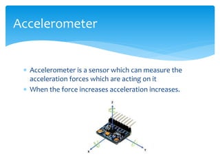
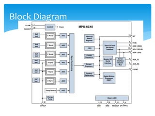
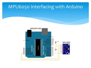
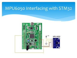
MPU6050 MOTION SENSOR
 GY-521 is a breakout board for the MPU-6050
which is a microelectrical mechanical system
 MPU6050 is the first integrated 6-axis Motion
Tracking device that combines a 3-axis gyroscope 3-
axis accelerometer,Temperature Sensor and
DMP(Digital Motion Processor) on a single ic.
 DMP correlates the data from accelerometer and
gyroscope
Introduction
 DMP can also use external 3rd party sensors such as
magnetometer
 External sensors connect using 2nd I2C bus
 MPU6050 sensor can communicate with the various
microcontroller using I2C interface
 The MPU6050 is a 6-axis IMU sensor it will give 6
values in output
 Three values from accelerometer and three from
Gyroscope.
Introduction
 Accelerometer measures the Acceleration forces
exerted on the x,y,z axes.
 Gyroscope measures the rotational movement of an
object over the axes x,y,z
Principle
 Accelerometer is a sensor which can measure the
acceleration forces which are acting on it
 When the force increases acceleration increases.
Accelerometer
 Consider the sensor resting on a table. At rest there
is no force acting on the sensor? There fore all the
axes have to get zero readings.
 But actually this is wrong. If there are no dynamic
forces are acting on the sensor also there is a static
force acting on it. That is the acceleration due to
gravity g .9.8m/s2
 This is acting perpendicular to the sensor
Accelerometer
 When you shake this sensor there are different values
across different axes.
 If you shake the sensor faster values across the axes
are increases. If you shake slowly then the values
across the axes are decreases.
 The micro crystals inside the sensors will produce raw
readings which are directly proportional to the forces
exerted on the sensor
Accelerometer
 Gyroscope measures rotational movement of the object
across its axes.
 Gyroscope in MPU-6050 is a ‘Mems Gyroscope”
 MEMS=“Micro Electro Mechanical System”
Gyroscope
 MEMS sensors produces a voltage when an axis is
rotated
 Voltage is sampled with a 16-bit ADC
 The unit in which how fast the object is rotating is
given by deg/sec in gyro.
 Gyroscope will not affect the vibrational force acting
across the object.
Gyroscope
Block Diagram
Schematic
 The gyroscope present in the MPU6050 can detect
the rotation about the axes x,y,z.
 Coriolis effect causes a vibration when the gyros are
rotated about any of these axes.
 These vibrations are picked up by the capacitor .
 The signal produced is then amplified ,demodulated
and filtered to produce the voltage that is
proportional to the angular rate
Explanation
 This voltage is then digitized using ADC’s
 The Digital motion processor present on the sensor
offloads the computation of the motion-sensing
algorithm from the host computer.
 DMP acquires data from all the sensors and stores the
computed values in its data resistor or FIFO
 FIFO can be accessed through the serial interface
Explanation
 Using AD0 pin more MPU6050 sensor module can be
interfaced with the microprocessor.
 I2C lines of MPU6050 are pulled high using 407Kohm
resistor and interrupt pin is pulled down using
4.7kohm resistor
 When data available in FIFO the interrupt pin goes
high
 Then a ,icrocontroller can read the data using I2C
communication bus.
Explanation
 Pin-1- CLKIN- is the optional external reference clock
input. This pin is connected to ground when not in
use.
 Pin-2, Pin-3, Pin-4, Pin-5 are NC pins. These Pins are
not connected internally.
 Pin-6, AUX_DA, is the I2C master serial data pin. This
pin is used for connecting external sensors.
 Pin-7, AUX_CL, is the I2C master serial clock. This pin is
used for connecting external sensors.
Pin Description
 Pin-8, VLOGIC, is the digital I/O supply voltage pin.
 Pin-9, AD0, is the I2C slave address LSB pin.
 Pin-10, REGOUT, is the regulator filter capacitor
connection.
 Pin-11, FSYNC, is the frame synchronization digital
input. This pin is connected to ground when not used.
Pin Description
 Pin-12, INT, is the interrupt digital output pin.
 Pin-13, VDD, is the power supply voltage pin.
 Pin-14, Pin-15, Pin-16, Pin-17 are NC pin. These pins are
not connected internally.
 Pin-18, GND, is the power supply ground.
 Pin-19 and Pin-21 are the RESV pins. These pins are
reserved.
PIN DESCRIPTION
 Pin-20, CPOUT, is the charge pump capacitor
connection.
 Pin-22, is RESV, the reserved pin.
 Pin-23, SCL, is the I2C serial clock.
 Pin-24, SDA, is the I2C serial data pin.
Pin Description
MPU6050 Interfacing with Arduino
MPU6050 Interfacing with STM32
 Sensor Combined 3-axis accelerometer and 3-axis
gyroscope values combined
 Power suply :3-5V
 It uses I2C protocol for communication
 Built in 16-ADC provides high accuracy
 Built in DMP provides high computational power
 Can be interfaced with magnetometer
Features of the MPU6050
 Sensor uses low pass filter for accelerometer,
gyroscope(digitally programmable) and temperature
sensor
 Gyroscope needs 3.6 mA of current for operating
 Accelerometer on the MPU6050 operates on
500micro amp of current
 Gyroscope has improved Low frequency noice
performance.
Features of the MPU6050
 DMP present on this sensor supports 3D motion
processing and gesture recognition algorithms
 MPU6050 has an optional external clock input of
32.768Khz or 19.2Mhz
 Embedded temperature sensor
Features of the MPU6050
 It has combined 3-axis accelerometer and 3-axis
gyroscope,Temperature sensor and DMP on a single
Chip
 Digital motion processor is embedded on the same
silicon die since it supports motion fusion algorithms
Advantages of MPU6050
 It is very complex device.
Disadvantages
 Used in orientation/Rotation Detector
 Tilt Sensor
 Humanoid robotics
 Robotic arm control
 Self balancing robot
 Drone /quad copters
 Used for IMU measurement
 Rockets ,aircrafts etc
Applications

MPU6050_Motion_Sensor.pptx

  • 1.
  • 2.
     GY-521 isa breakout board for the MPU-6050 which is a microelectrical mechanical system  MPU6050 is the first integrated 6-axis Motion Tracking device that combines a 3-axis gyroscope 3- axis accelerometer,Temperature Sensor and DMP(Digital Motion Processor) on a single ic.  DMP correlates the data from accelerometer and gyroscope Introduction
  • 3.
     DMP canalso use external 3rd party sensors such as magnetometer  External sensors connect using 2nd I2C bus  MPU6050 sensor can communicate with the various microcontroller using I2C interface  The MPU6050 is a 6-axis IMU sensor it will give 6 values in output  Three values from accelerometer and three from Gyroscope. Introduction
  • 4.
     Accelerometer measuresthe Acceleration forces exerted on the x,y,z axes.  Gyroscope measures the rotational movement of an object over the axes x,y,z Principle
  • 5.
     Accelerometer isa sensor which can measure the acceleration forces which are acting on it  When the force increases acceleration increases. Accelerometer
  • 6.
     Consider thesensor resting on a table. At rest there is no force acting on the sensor? There fore all the axes have to get zero readings.  But actually this is wrong. If there are no dynamic forces are acting on the sensor also there is a static force acting on it. That is the acceleration due to gravity g .9.8m/s2  This is acting perpendicular to the sensor Accelerometer
  • 7.
     When youshake this sensor there are different values across different axes.  If you shake the sensor faster values across the axes are increases. If you shake slowly then the values across the axes are decreases.  The micro crystals inside the sensors will produce raw readings which are directly proportional to the forces exerted on the sensor Accelerometer
  • 8.
     Gyroscope measuresrotational movement of the object across its axes.  Gyroscope in MPU-6050 is a ‘Mems Gyroscope”  MEMS=“Micro Electro Mechanical System” Gyroscope
  • 9.
     MEMS sensorsproduces a voltage when an axis is rotated  Voltage is sampled with a 16-bit ADC  The unit in which how fast the object is rotating is given by deg/sec in gyro.  Gyroscope will not affect the vibrational force acting across the object. Gyroscope
  • 10.
  • 11.
  • 12.
     The gyroscopepresent in the MPU6050 can detect the rotation about the axes x,y,z.  Coriolis effect causes a vibration when the gyros are rotated about any of these axes.  These vibrations are picked up by the capacitor .  The signal produced is then amplified ,demodulated and filtered to produce the voltage that is proportional to the angular rate Explanation
  • 13.
     This voltageis then digitized using ADC’s  The Digital motion processor present on the sensor offloads the computation of the motion-sensing algorithm from the host computer.  DMP acquires data from all the sensors and stores the computed values in its data resistor or FIFO  FIFO can be accessed through the serial interface Explanation
  • 14.
     Using AD0pin more MPU6050 sensor module can be interfaced with the microprocessor.  I2C lines of MPU6050 are pulled high using 407Kohm resistor and interrupt pin is pulled down using 4.7kohm resistor  When data available in FIFO the interrupt pin goes high  Then a ,icrocontroller can read the data using I2C communication bus. Explanation
  • 15.
     Pin-1- CLKIN-is the optional external reference clock input. This pin is connected to ground when not in use.  Pin-2, Pin-3, Pin-4, Pin-5 are NC pins. These Pins are not connected internally.  Pin-6, AUX_DA, is the I2C master serial data pin. This pin is used for connecting external sensors.  Pin-7, AUX_CL, is the I2C master serial clock. This pin is used for connecting external sensors. Pin Description
  • 16.
     Pin-8, VLOGIC,is the digital I/O supply voltage pin.  Pin-9, AD0, is the I2C slave address LSB pin.  Pin-10, REGOUT, is the regulator filter capacitor connection.  Pin-11, FSYNC, is the frame synchronization digital input. This pin is connected to ground when not used. Pin Description
  • 17.
     Pin-12, INT,is the interrupt digital output pin.  Pin-13, VDD, is the power supply voltage pin.  Pin-14, Pin-15, Pin-16, Pin-17 are NC pin. These pins are not connected internally.  Pin-18, GND, is the power supply ground.  Pin-19 and Pin-21 are the RESV pins. These pins are reserved. PIN DESCRIPTION
  • 18.
     Pin-20, CPOUT,is the charge pump capacitor connection.  Pin-22, is RESV, the reserved pin.  Pin-23, SCL, is the I2C serial clock.  Pin-24, SDA, is the I2C serial data pin. Pin Description
  • 19.
  • 20.
  • 21.
     Sensor Combined3-axis accelerometer and 3-axis gyroscope values combined  Power suply :3-5V  It uses I2C protocol for communication  Built in 16-ADC provides high accuracy  Built in DMP provides high computational power  Can be interfaced with magnetometer Features of the MPU6050
  • 22.
     Sensor useslow pass filter for accelerometer, gyroscope(digitally programmable) and temperature sensor  Gyroscope needs 3.6 mA of current for operating  Accelerometer on the MPU6050 operates on 500micro amp of current  Gyroscope has improved Low frequency noice performance. Features of the MPU6050
  • 23.
     DMP presenton this sensor supports 3D motion processing and gesture recognition algorithms  MPU6050 has an optional external clock input of 32.768Khz or 19.2Mhz  Embedded temperature sensor Features of the MPU6050
  • 24.
     It hascombined 3-axis accelerometer and 3-axis gyroscope,Temperature sensor and DMP on a single Chip  Digital motion processor is embedded on the same silicon die since it supports motion fusion algorithms Advantages of MPU6050
  • 25.
     It isvery complex device. Disadvantages
  • 26.
     Used inorientation/Rotation Detector  Tilt Sensor  Humanoid robotics  Robotic arm control  Self balancing robot  Drone /quad copters  Used for IMU measurement  Rockets ,aircrafts etc Applications